Blast Erosion
Blast erosion is the deterioration of airport infrastructure caused by the high-speed, high-temperature jet exhaust from aircraft engines. It affects surfaces l...
5 min read
Airport safety
Runway maintenance
+2
Abrasion is the progressive loss of concrete pavement surface material caused by mechanical wear from traffic, studded tires, debris, and jet blast. In airport pavements, abrasion reduces surface texture and friction, generates FOD, and requires systematic testing per ASTM standards, differentiation from scaling and raveling, and targeted prevention and repair strategies.
Abrasion is the progressive loss of surface material from a concrete pavement caused by mechanical wear — specifically the rubbing, scraping, grinding, cutting, and impact actions of traffic, equipment, and environmental forces acting on the pavement surface. In airport pavements, this primarily results from aircraft tire friction during landing and taxiing, jet blast effects, and the grinding action of foreign object debris trapped between tires and the pavement surface.
The abrasion process in concrete pavements operates through several distinct physical mechanisms occurring at the microscopic and macroscopic levels. Sliding wear occurs when frictional contact between aircraft tire rubber and the concrete surface generates tangential forces that shear off microscopic layers of the cement paste — this is the dominant mechanism in straight-line traffic areas. Scuffing wear results from lateral tire movement during turning maneuvers on taxiways and aprons, producing localized shear stresses that tear and displace surface material. Grinding wear happens when abrasive particles such as sand, dust, runway debris, and pulverized rubber become trapped between tires and pavement, acting as lapping agents that accelerate material removal. Impact wear arises from repeated dynamic loading during aircraft landings, causing micro-cracking and fatigue of the surface layer that makes it more susceptible to subsequent material removal. Erosion wear occurs when high-velocity jet blast propels loose particles across the pavement, creating an impingement erosion effect analogous to sandblasting.
The rate and severity of abrasion are governed by several material and operational factors. Concrete strength and quality are paramount — abrasion resistance correlates directly with compressive strength, and lower water-cement ratios (below 0.45 per ACI 201.2R) produce denser, harder paste with significantly greater resistance to wear. Aggregate hardness and polish resistance control how long the surface maintains its frictional texture once the cement paste matrix is worn away. Curing adequacy is critical because poor curing leaves a weak, friable surface layer susceptible to rapid abrasion. Traffic characteristics including the magnitude, frequency, and type of loading (dynamic versus static, straight versus turning) dictate the abrasion rate. Environmental exposure such as wet-dry cycling, freeze-thaw action, and chemical exposure from de-icing fluids can weaken the surface layer and accelerate the abrasion process.
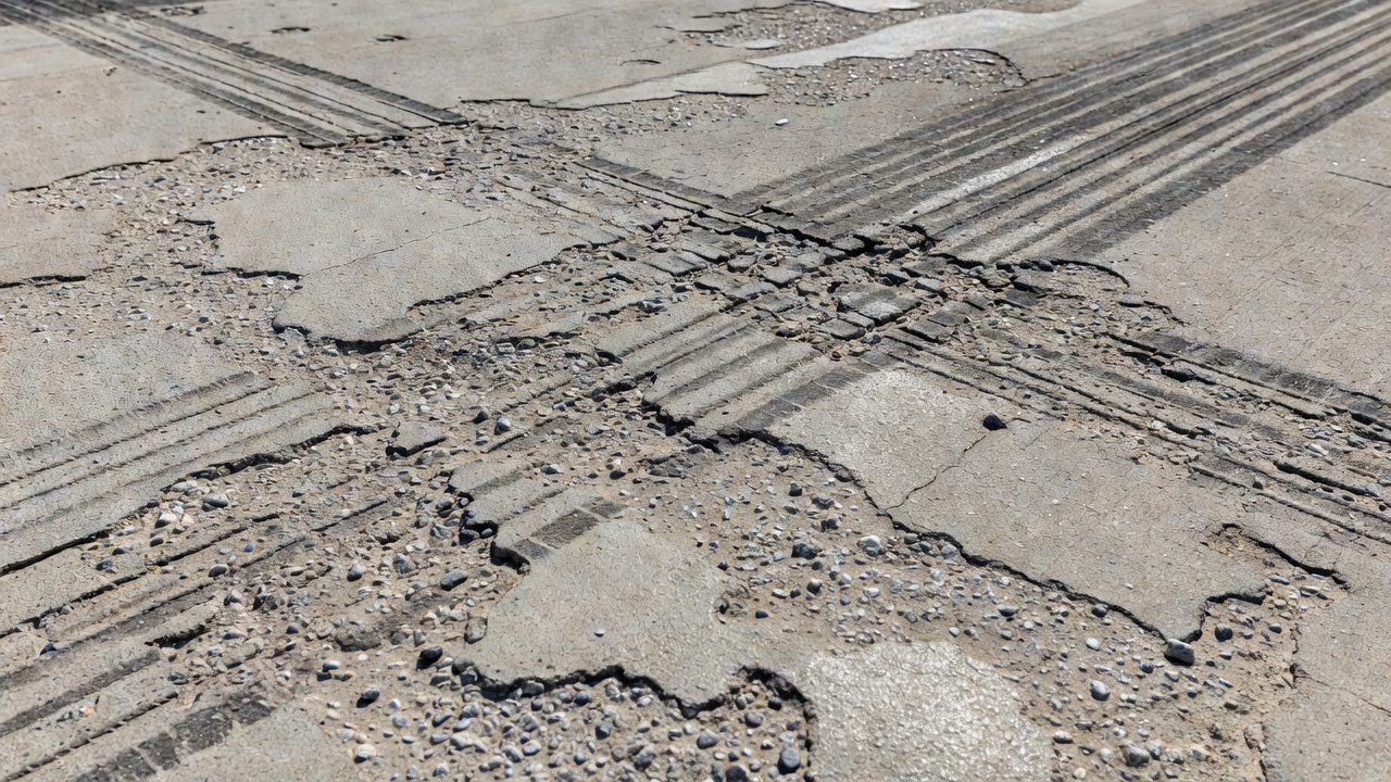
The visible manifestations of abrasion follow a predictable progression. Initially, the surface mortar or cement paste wears away, exposing fine aggregate particles. With continued traffic, the exposed fine aggregate becomes polished and the coarse aggregate begins to protrude above the worn mortar matrix. In advanced stages, the coarse aggregate itself may become polished or fractured, the surface texture becomes smooth and shiny (particularly when wet), and measurable loss of the surface profile occurs. This progression directly correlates with reduced friction coefficients and increased hydroplaning risk on runways.
While concrete abrasion occurs in both highway and airport pavements, the mechanisms, severity, and operational implications differ substantially between the two applications. These differences drive distinct design requirements, maintenance strategies, and regulatory frameworks.
Tire pressures represent the most significant difference. Aircraft tires operate at substantially higher inflation pressures than highway vehicle tires — up to 240 psi (1.65 MPa) for large commercial aircraft compared to 80–120 psi (0.55–0.83 MPa) for heavy trucks. This higher contact pressure concentrates abrasive forces into a smaller tire footprint area, increasing unit wear on the concrete surface by an order of magnitude. The contact stress beneath an aircraft tire during landing can exceed 300 psi momentarily, creating extreme surface shear conditions.
Loading characteristics differ fundamentally. Highway traffic produces channelized wear patterns from repeated vehicle passes in the same wheel tracks. Airport pavements experience concentrated wear in the runway touchdown zone from braking during landing rollout, along taxiway centerlines from straight-line taxiing, and at apron stand positions from turning and static parking loads. The speed range at airports spans from taxiing at approximately 20 knots to landing at 140–180 knots, creating a wide range of tire-pavement interaction dynamics.
Braking forces on airport pavements are exceptionally high during landing rollout when aircraft deploy reverse thrust and heavy braking simultaneously. These forces generate maximum tangential shear at the tire-pavement interface, rapidly wearing the surface paste in the touchdown zone. Highway braking, while frequent, involves significantly lower energy dissipation per braking event.
Thermal effects are unique to airport pavements. Jet blast from aircraft engines can produce exhaust gas temperatures exceeding 500°C at the nozzle exit, and while concrete resists thermal degradation better than asphalt, repetitive thermal cycling can contribute to surface microcracking. Highway pavements experience only ambient thermal conditions.
Abrasive contaminants at airports include rubber deposits from aircraft landings — a significant issue requiring periodic rubber removal as standard maintenance — along with jet fuel, hydraulic fluid, de-icing chemicals, and a broader range of foreign object debris. Highway pavements contend primarily with road grit, sand, and de-icing salts.
Friction requirements are more stringent for airport pavements because of higher operating speeds, the criticality of braking performance for landing safety, and the severe consequences of hydroplaning at high speeds. Per FAA AC 150/5320-12C, airport runways are classified based on friction measurements, with minimum friction coefficients required for continued safe operations.
Design implications per FAA AC 150/5320-6G and ICAO Doc 9157 require airfield pavements to withstand higher tire pressures, jet blast effects, fuel and chemical spillage resistance, and stringent friction requirements throughout the pavement service life.
Jet blast erosion is a distinct form of abrasion specific to airfield pavements, resulting from the high-velocity exhaust gases produced by jet aircraft engines. These exhaust gases generate several damaging effects on pavement surfaces. The primary mechanism is mechanical: high-velocity gas propels loose debris across the pavement surface at speeds sufficient to create impingement erosion. A secondary mechanism is thermal: repetitive exposure to hot exhaust can cause thermal degradation, although concrete inherently resists thermal damage better than asphalt.
The regulatory framework for jet blast protection is established by multiple authorities. FAA AC 150/5320-6G (Airport Pavement Design and Evaluation) addresses jet blast effects primarily in the context of shoulder design and erosion protection, mandating that shoulders be designed to resist erosion from jet blast and requiring stabilized bases for pavements serving aircraft over 100,000 pounds. FAA AC 150/5380-6C (Guidelines and Procedures for Maintenance of Airport Pavements) states that airport pavements must be durable enough to withstand the abrasive action of traffic, weather, and other deteriorating influences, and classifies surface disintegration as a distinct distress category for rigid pavements. ICAO Doc 9157 (Aerodrome Design Manual, Part 3 — Pavements) provides guidance on pavement surface characteristics including resistance to abrasion and erosion, friction maintenance requirements, and surface texture requirements.
For concrete pavements specifically, jet blast erosion manifests as surface discoloration in areas directly behind aircraft engine positions, loss of surface paste in localized areas, accelerated wear at apron edges, runway thresholds, and engine run-up areas, and loosening of aggregate particles at mortar boundaries. Concrete offers inherently greater resistance to jet blast than asphalt — per ACPA publication IS202, high-temperature jet engine blasts do not adversely affect concrete pavement surfaces, and concrete is not damaged by fuel spillage, oil drippings, or jet heat and blast. However, prolonged exposure can still accelerate surface wear by propelling debris across the surface, cause thermal cycling that contributes to surface microcracking over time, and erode joint sealant materials leading to water infiltration.
Turning effects at airports create additional abrasion mechanisms. Aircraft turning on taxiways and aprons generates lateral shear stresses at the tire-pavement interface that are significantly higher than those produced by straight-line traffic. These lateral forces tear and displace surface material through scuffing action. The problem is particularly acute at runway turnoff junctions, apron corners, and aircraft stand positions where heavy aircraft execute tight-radius turns under their own power. The resulting abrasion patterns follow the turning path geometry and can create localized depressions and polished surfaces within the turning zones.
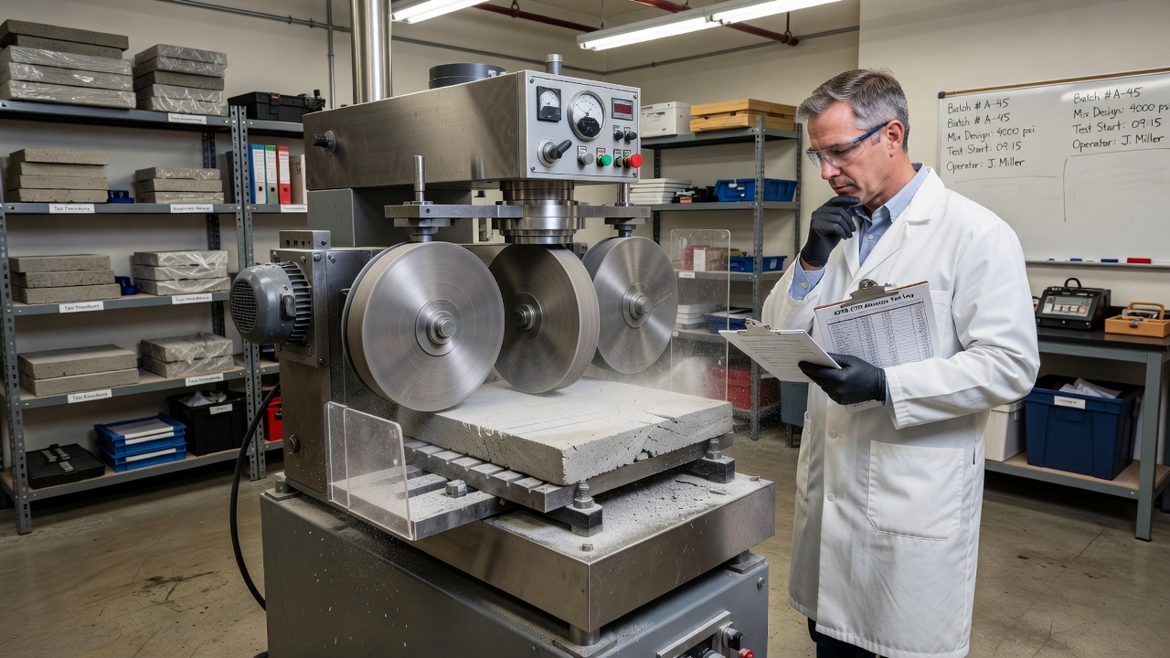
The abrasion resistance of concrete pavements is evaluated through several standardized test methods established by ASTM International. Each method simulates different wear mechanisms and is appropriate for different applications.
This standard provides three distinct procedures for determining the relative abrasion resistance of horizontal concrete surfaces. The choice of procedure depends on the type of wear mechanism being simulated.
Procedure A — Revolving-Disk Machine simulates sliding and scuffing wear from abrasive grit, representing light-to-medium traffic abrasion. The apparatus consists of a machine with three rotating steel disks, each 70 mm in diameter, rotating at approximately 300 rpm. Silicon carbide abrasive grit (No. 60) is fed between the disks and the concrete surface at a controlled rate of 4–6 grams per minute, with approximately 20 N of load applied per disk. The test runs for 30–60 minutes, and the depth of wear is measured using a dial gauge or depth micrometer. Results are reported as average depth of wear in inches or millimeters at specified intervals.
Procedure B — Dressing-Wheel Machine simulates the rolling, pounding, and cutting action of steel-wheeled traffic, representing heavy traffic abrasion. The apparatus uses three sets of seven dressing wheels mounted on horizontal shafts, each wheel approximately 57 mm in diameter. No abrasive grit is used — the wheels create wear through direct contact with the concrete surface, producing approximately double the depth of wear compared to Procedure A for the same test duration. After the test, the depth of the wear path is measured at multiple points, and the surface condition is assessed to determine how harder aggregate particles stand out from the softer paste that abrades more quickly.
Procedure C — Ball-Bearing Machine simulates impact plus sliding friction, representing heavy steel-wheeled and tracked traffic. The apparatus uses eight steel ball bearings (12.7 mm diameter) rotating under load at 1,000 rpm, with water used as a flushing medium to remove loose particles. Wear readings are taken every 50 seconds over a total test duration of 1,200 seconds (20 minutes), and results are plotted as wear depth versus time. The test can be terminated early if a maximum depth of 3.0 mm is reached.
This method simulates the grinding and cutting forces from heavy machinery and steel-wheeled equipment, making it particularly applicable to industrial and airfield pavements. The apparatus consists of a rotating steel cutter (similar to a face milling cutter) mounted in a drill press with a constant load mechanism applying 98 N (22 lbf) directly to the spindle, rotating at approximately 200 rpm. No abrasive grit is required.
The test procedure uses specimens obtained as drilled cores (minimum 100 mm diameter) or sawn beams. After conditioning, each specimen is mounted in the test apparatus, the constant load is applied to the rotating cutter, and the test runs for 2-minute periods. The specimen mass loss is measured to the nearest 0.01 g after each cycle, typically over three 2-minute cycles or longer. Results are reported as mass loss in grams, which can be converted to volume loss if the concrete density is known.
This method simulates erosive wear from abrasive particles carried by water or traffic, representing waterborne debris and windborne particle abrasion. The apparatus includes a blast cabinet with an injector-type blast gun, high-velocity air jet, and controlled abrasive feed of silica sand or similar material. The test parameters — air pressure, nozzle distance, abrasive gradation, and feed rate — are adjustable to match specific conditions. Results are measured as volume loss or depth of wear.
This method simulates abrasion by waterborne particles in hydraulic structures. The specimen is submerged in a water-filled container with steel grinding balls of various sizes, agitated at 1,200 rpm to create circular water flow that moves the grinding balls across the specimen surface. The test consists of six 12-hour periods (72 hours total) with specimen mass loss measured after each period.
| Abrasion Type | C418 | C779-A | C779-B | C779-C | C944 | C1138 |
|---|---|---|---|---|---|---|
| Light to medium traffic | ✓ | ✓ | ✓ | ✓ | ✓ | |
| Heavy/steel-wheeled traffic | ✓ | ✓ | ✓ | ✓ | ||
| Heavy tracked/chain traffic | ✓ | ✓ | ✓ | |||
| Hydraulic structures | ✓ |
Abrasion directly degrades both components of pavement surface texture — microtexture and macrotexture — which together determine the frictional properties of the pavement surface. Per FAA AC 150/5320-12C, microtexture is the fine-scale roughness contributed by small individual aggregate particles, not readily discernible to the eye but apparent to the touch like fine sandpaper. Macrotexture is the visible roughness of the pavement surface as a whole, providing drainage channels for water to escape from beneath aircraft tires.
Microtexture provides the sharpness that allows tire rubber to penetrate the residual water film on the pavement surface at low speeds. As abrasion progresses, the cement paste is worn away, exposing fine aggregate particles. Continued traffic polishes these exposed particles, rounding their sharp edges and reducing their micro-asperity. The polished surface may appear shiny when wet, and without adequate microtexture, the tire cannot effectively break through the residual water film at low speeds, resulting in reduced braking capability.
Macrotexture provides escape paths for bulk water beneath the tire at high speeds, preventing hydroplaning. Repeated tire contact gradually flattens surface irregularities, grooves, and tining patterns become shallower, and the overall surface roughness diminishes. As macrotexture is lost, the pavement’s ability to drain water from beneath the tire contact patch is compromised, increasing hydroplaning risk, particularly at the high speeds typical of aircraft landing and takeoff.
Rubber deposit overlay compounds the texture degradation. Aircraft tires deposit substantial rubber during landings, particularly in the touchdown zone. This rubber layer can completely cover the pavement surface texture, filling grooves and masking whatever microtexture and macrotexture remain. Heavy rubber deposits cause loss of braking capability and directional control on wet runways, requiring periodic rubber removal as part of standard airport maintenance programs.
The FAA classifies runway friction based on measurements taken with Continuous Friction Measuring Equipment (CFME) per AC 150/5320-12C. Runways with friction coefficients of 0.60 or above at 65 km/h (40 mph) are classified as Good requiring only routine monitoring. Runways with friction coefficients between 0.40 and 0.59 are classified as Medium requiring investigation and planned corrective action. Runways with friction coefficients below 0.40 are classified as Poor requiring urgent corrective action.
FAA AC 150/5320-12C recommends minimum macrotexture depths of 0.8 mm (0.03 inches) for new pavements, with in-service pavements required to maintain adequate texture for friction requirements. Measurement methods include the sand patch test (volumetric technique using spread diameter of a known volume of sand or glass beads), the grease volume technique, and laser profilometry for advanced non-contact measurement.
Abrasion must be distinguished from other concrete surface distress types — particularly scaling and raveling — because each has different causes, mechanisms, depth characteristics, and repair strategies. Confusing these distress types can lead to inappropriate maintenance actions.
Abrasion is strictly a surface-level phenomenon confined to the cement paste and fine mortar fraction, typically less than 3 mm (⅛ inch) deep. It results from mechanical wear caused by traffic friction, tire contact, and abrasive debris. The distribution follows traffic patterns — wheel paths, touchdown zones, turnoff locations — and does not extend into non-traffic areas. In its early stages, abrasion removes only the surface paste, exposing fine aggregate. In advanced stages, coarse aggregate becomes exposed and may become polished. Abrasion typically does not produce loose debris until very advanced stages, and its primary operational impact is friction loss rather than FOD generation.
Scaling (PAVER Distress Code 70 for concrete pavements) is the localized flaking or peeling away of surface mortar to depths of 3–13 mm (⅛–½ inch), deeper than abrasion. It involves loss of the mortar fraction rather than just surface paste, frequently exposing coarse aggregate with a rough, pitted appearance. Scaling results from fundamentally different causes than abrasion: construction defects such as over-finishing or inadequate curing, material defects including low-strength concrete or high water-cement ratios, environmental factors including freeze-thaw cycling and de-icing chemical attack, and alkali-silica reaction (ASR). Unlike abrasion, scaling can affect large areas including non-traffic zones and entire slab surfaces. The PAVER system defines three severity levels for scaling: Low (slightly rough surface, no exposed coarse aggregate), Medium (rough and pitted surface, coarse aggregate exposed and may be broken), and High (coarse aggregate exposed and broken with significant loss of surface material).
Raveling (PAVER Distress Code 52) is a different phenomenon that affects asphalt pavements rather than concrete. It involves the dislodging of aggregate particles from the pavement surface due to loss of binder-aggregate bond. The mechanism is binder failure — aging, oxidation, or stripping of the asphalt film from aggregate particles. Raveling creates a rough surface texture with loose particles present, and in airport environments, these loose particles become foreign object debris (FOD) that presents a serious ingestion hazard to jet engines. Raveling is not a concrete distress but is listed here because it is sometimes confused with concrete abrasion in composite pavement systems or when asphalt surfaces overlay concrete.
Polished aggregate (PAVER Distress Code 51) is a separate distress where aggregate exposed at the surface has become smooth and polished from repeated traffic. While related to abrasion, polished aggregate is specifically about aggregate surface condition rather than loss of material. In concrete pavements, polished aggregate is not a separate distress code but is captured through friction testing and macrotexture measurement.
The key distinction principles are: abrasion is strictly surface-level paste wear from mechanical traffic forces; scaling is deeper mortar disintegration from material or environmental causes; raveling is binder failure in asphalt pavements causing aggregate dislodgment. Distribution patterns further differentiate them — abrasion follows traffic patterns while scaling can occur over entire slab areas including non-traffic zones.
The severity of abrasion damage in concrete pavements is assessed through multiple complementary methods, ranging from visual inspection to quantitative friction measurement and non-destructive testing.
Visual assessment using the Pavement Condition Index (PCI) method per ASTM D5340 provides systematic evaluation of pavement condition. While abrasion is not a standalone distress code in the concrete PCI system, its effects are captured through the scaling distress code (Code 70) at three severity levels and through friction testing. The PCI system uses deduct value curves for each distress type at each severity level to calculate overall PCI scores on a 0–100 scale, guiding maintenance and rehabilitation decisions. The US Army Corps of Engineers PAVER system provides specific deduct value tables for rigid pavement distresses.
Friction measurement per FAA AC 150/5320-12C is the most direct method of assessing abrasion impact on operational safety. The FAA requires periodic friction surveys using CFME at minimum frequencies based on traffic levels: runways with 90 or more jet operations per day require quarterly surveys; runways with 16–89 jet operations per day require semi-annual surveys; runways with 15 or fewer jet operations per day require annual surveys; and runways used exclusively by propeller aircraft require surveys every two years. Test speeds are typically 65 km/h (40 mph) and 95 km/h (60 mph).
Macrotexture depth measurement using the sand patch test provides quantitative assessment of surface drainage capacity. A known volume of sand or glass beads is spread on the pavement surface, the spread diameter is measured, and texture depth is calculated as (4 × volume) / (π × diameter²). Minimum recommended texture depth is 0.8 mm for new pavements.
Groove condition assessment for grooved runways evaluates groove depth, width, spacing uniformity, extent of groove edge raveling, and rubber accumulation in grooves. Groove deterioration reduces the effectiveness of the drainage system and increases hydroplaning risk.
Non-destructive testing methods per FAA AC 150/5380-6C include Falling Weight Deflectometer (FWD) for measuring structural capacity, Ground Penetrating Radar (GPR) for identifying subsurface defects, and chain dragging or hammer sounding for delamination detection. While these methods do not directly measure surface abrasion, they help determine whether surface wear has progressed to the point of affecting structural integrity.
Preventing abrasion in concrete pavements begins with proper mix design and continues through construction practices, surface treatments, and operational maintenance. The most effective prevention strategy addresses all stages of the pavement lifecycle.
Concrete mixture design for abrasion resistance requires several key elements. Low water-cement ratios (typically below 0.45 per ACI recommendations) produce denser, harder paste with greater resistance to wear. The selection of hard, polish-resistant coarse aggregates is critical because aggregate hardness controls long-term abrasion resistance once the cement paste is worn away. Preferred aggregates include siliceous gravels, crushed granite, basalt, and quartzite. Soft aggregates such as limestone and sandstone should be avoided in surface courses. The use of the largest practical aggregate size improves abrasion resistance per ACI 210R. Supplementary cementitious materials, particularly silica fume, have demonstrated excellent abrasion resistance under adverse conditions per ACI 210.1R. High-strength concrete with compressive strength of at least 34.5 MPa (5,000 psi) is typical for airfield pavements, with FAA construction specifications typically requiring minimum 28-day flexural strength of 4.5 MPa (650 psi).
Construction practices significantly influence abrasion resistance. Proper finishing avoids over-finishing, which can bring excess water and fines to the surface, creating a weak, friable surface layer. The timing of finishing operations must be carefully controlled. Adequate curing — extended wet curing for 7–14 days minimum — is essential for surface hardness, and curing compounds must be applied immediately after finishing to prevent plastic shrinkage cracking and ensure complete hydration.
Surface texturing establishes initial macrotexture and friction. Methods include broom or brush finish for macrotexture, burlap drag for fine transverse texture, wire combing or tining for mechanical texturing, and plastic grooving formed during construction using vibrating ribbed plates or ribbed roller tubes. Saw-cut grooves after concrete hardens provide more controlled geometry for runway applications.
Surface treatments can enhance or preserve abrasion resistance. Penetrating sealers based on silanes and siloxanes reduce water absorption and freeze-thaw damage, indirectly preserving surface quality. Liquid chemical hardeners based on sodium silicate, lithium silicate, or potassium silicate react with free calcium hydroxide in the concrete to form calcium silicate hydrate (CSH), densifying the surface layer and improving resistance to abrasion. Polymer and epoxy coatings provide enhanced abrasion resistance for industrial applications, though they must be compatible with thermal expansion and provide UV stability for outdoor use.
Operational prevention includes regular rubber removal from runway touchdown zones, prompt debris removal to prevent abrasive action between tires and pavement, effective drainage to minimize water-related weakening of the surface layer, and regular friction monitoring to detect deterioration at an early stage when corrective action is less costly.
Repair strategies for abraded concrete pavements are selected based on the depth and extent of surface loss, operational requirements, and available maintenance windows. The classification of repair types follows the depth of damage.
| Repair Type | Depth Condition | Application |
|---|---|---|
| Surface restoration | Less than 6 mm (¼ in) | Light abrasion, friction restoration |
| Partial-depth repair | 6 mm to ⅓ slab depth | Spalls, scaling, deeper abrasion |
| Thin bonded overlay | 25–50 mm (1–2 in) | Widespread surface deterioration |
| Full-depth repair | More than ⅓ slab depth | Structural damage, shattered slabs |
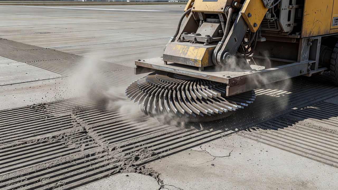
Diamond grinding is the primary surface restoration technique for pavements with abrasion and polishing. The process uses self-propelled grinding machines with closely spaced diamond-tipped saw blades to remove 6–10 mm (¼–⅜ inch) of surface material, creating a new surface texture with a transverse corduroy pattern. This restores macrotexture for water drainage, improves friction immediately, and can correct cross-slope deficiencies and joint faulting. Diamond grinding extends pavement life without structural increase, involves no change to pavement elevation beyond the material removed, and is cost-effective compared to overlay or reconstruction. Per FAA AC 150/5380-6C and ACPTP research, diamond grinding is the preferred method for restoring friction to concrete pavements that have become polished or lightly abraded.
Partial-depth repair is applicable to spalls, localized scaling, joint deterioration, and isolated deeper abrasion damage. The procedure per ACPA and FAA guidance involves defining repair boundaries at a minimum of 75 mm (3 inches) beyond visible damage, removing unsound concrete to a minimum depth of 50 mm (2 inches) not exceeding one-third of the slab thickness, cleaning the cavity thoroughly, applying a bonding agent, placing repair material (proprietary repair mortar, polymer concrete, or rapid-setting cementitious material), and curing the repair. FAA AC 150/5380-6C references rapid-setting cementitious materials, polymer concretes, and epoxy concretes for restoring abraded surfaces.
Thin bonded overlays of 25–50 mm provide a new wearing course for pavements with widespread surface deterioration where individual partial-depth repairs would be impractical. The overlay bonds to the existing concrete surface after proper preparation including cleaning, scarification, and application of a bonding agent. Thin bonded overlays restore surface profile, friction, and appearance while adding minimal structural capacity.
Full-depth repair is reserved for situations where abrasion has progressed to the point of structural damage, typically when surface loss exceeds one-third of the slab thickness or when other structural distresses such as cracking or faulting are present. Full-depth repair involves removing the entire slab panel, preparing the base and subbase, placing and compacting base material, installing load transfer devices, placing new concrete, texturing, and curing.
Temporary repairs for emergency situations may use rapid-setting materials such as quick-setting cementitious patching compounds or cold-mix asphalt designed for temporary restoration of surface profile until permanent repairs can be scheduled.
Ensure your airport or highway pavements maintain optimal friction and structural integrity. Our experts provide abrasion assessment, prevention strategies, and repair solutions tailored to your operational demands and regulatory requirements.
Blast erosion is the deterioration of airport infrastructure caused by the high-speed, high-temperature jet exhaust from aircraft engines. It affects surfaces l...
Raveling is the progressive dislodgement and loss of aggregate particles from the pavement surface due to binder aging, oxidation, or poor compaction. In airpor...
Airport pavement is the engineered surface for aircraft operations—runways, taxiways, aprons—designed to withstand heavy loads, ensure safety, and support airpo...