Bridge Bearings
Bridge bearings are critical load-transfer devices at abutments and piers that transmit superstructure forces to the substructure while accommodating thermal mo...
28 min read
Bridge components
Bridge inspection
+3
An abutment is the end support structure of a bridge that retains the approach embankment, transfers superstructure loads to the foundation, and accommodates thermal movement. Abutment condition — cracking, settlement, scour, bearing failure — is a critical SNBI substructure element. Covers abutment types, distress modes, inspection, and condition rating.
A bridge abutment is a substructure unit located at each terminus of a bridge superstructure. It serves the dual purpose of supporting the bridge ends and retaining the approach roadway embankment. The abutment forms the structural transition between the bridge and the ground or roadway approach. Per the AASHTO LRFD Bridge Design Specifications (9th Edition, 2020), abutments are designed to resist combinations of vertical and horizontal loads including dead load (DC) from the superstructure components and wearing surfaces (DW), live load (HL-93 design truck and lane load), earth pressure (EH) from retained soil, earth surcharge (ES), braking forces (BR), wind loads on structure (WS) and live load (WL), temperature forces (TU), creep and shrinkage (CR, SH), and seismic forces.
The five primary functions of a bridge abutment are load transfer, earth retention, approach support, thermal accommodation, and erosion protection. Vertical load transfer carries the dead weight of the bridge deck, girders, barriers, and wearing surface plus the design live load from traffic to the foundation soil or piles. Horizontal load resistance counteracts active earth pressure from the approach embankment fill, which is calculated using Rankine or Coulomb earth pressure theory with load factors per AASHTO Strength I limit state (EH = 1.50/0.75, EV = 1.35/1.00). Embankment retention prevents approach roadway soil from encroaching onto the bridge span, maintaining clear span length and preventing fill material from accumulating on bearing seats. Approach slab support provides a smooth vehicular transition between the pavement and bridge deck, reducing impact loads from the bridge head bump phenomenon. Thermal movement accommodation occurs at the expansion joint (in seat-type abutments) or through pile flexure (in integral abutments) for temperature ranges typically spanning -20°F to +120°F per AASHTO LRFD Section 3.12.2.
The abutment is subjected to load factors defined in AASHTO LRFD Table 3.4.1-1. For Strength I limit state, the abutment self-weight (DC_sub) carries a factor of 1.25/0.90, earth pressure (EH) uses 1.50/0.75, vertical earth pressure on the heel (EV) uses 1.35/1.00, and live load (LL) uses 1.75. For seat-type abutments equipped with elastomeric bearings, the horizontal load transferred to the substructure is limited to 0.2(DC + DW) before bearing slippage occurs, as specified in AASHTO-CA Section 3.4.5. The live load surcharge (LS) behind the abutment is modeled as an equivalent soil height of 2 to 4 feet depending on abutment height (AASHTO 3.11.6.4).
Abutments are founded on spread footings when competent bearing soil exists at shallow depth, or on deep foundations including driven piles (steel H-piles, precast prestressed concrete piles, or timber piles) and drilled shafts. The passive earth pressure in front of the abutment is typically neglected in design due to the potential for scour or future excavation. The WisDOT Bridge Manual (Chapter 12) and Caltrans Bridge Design Practice (Section 11) provide comprehensive abutment design procedures including overturning, sliding, bearing pressure, and structural capacity checks.
Bridge abutments are classified by structural form, load-resisting mechanism, and the connection type between the superstructure and substructure. Each type is suited to specific site conditions, embankment heights, span lengths, and seismic requirements.
The cantilever abutment is the most common abutment type in modern highway bridge construction. It consists of a T-shaped reinforced concrete wall with a base slab comprising a toe (front) and heel (back) section. The vertical stem acts as a cantilever retaining wall resisting active earth pressure from the backfill. Bending and shear reinforcement is provided in the stem, with the primary vertical reinforcement placed on the earth side (rear face) and horizontal distribution steel throughout. The base slab requires reinforcement at both the top (heel) and bottom (toe) to resist bearing pressure variations. Cantilever abutments are used for medium to high approach embankments and are advantageous where differential settlement is a concern. The thinner wall section compared to gravity abutments reduces concrete volume, construction cost, and carbon footprint. Typical stem thickness ranges from 12 inches at the top to 36-48 inches at the base for a 20-foot tall abutment.
The gravity abutment relies entirely on its own mass to resist sliding and overturning from lateral earth pressure. It is constructed using mass concrete (unreinforced or minimally reinforced), stone masonry, gabion baskets, or large precast concrete blocks. The wide base required for stability means gravity abutments are material-intensive and uneconomical for tall embankments. They are best suited for short-span, low-level bridges where the underlying soil provides competent bearing capacity for the wide footing. The limiting height for economical gravity abutment construction is approximately 15-20 feet. Foundation is typically a spread footing on competent bearing soil or rock.
The counterfort abutment incorporates full-height triangular buttressing walls — called counterforts — on the earth side at regular intervals of 10 to 15 feet. These counterforts act as vertical stiffeners providing extra bending resistance to the back wall, allowing a significantly thinner wall section than a cantilever design. Counterfort abutments are specified for very tall approach embankments exceeding 25 to 40 feet in height. The reduced wall thickness saves concrete and reinforcement material costs, though the formwork and reinforcement detailing are substantially more complex, increasing labor costs. Counterfort spacing and thickness are determined by structural analysis per AASHTO LRFD Section 11.
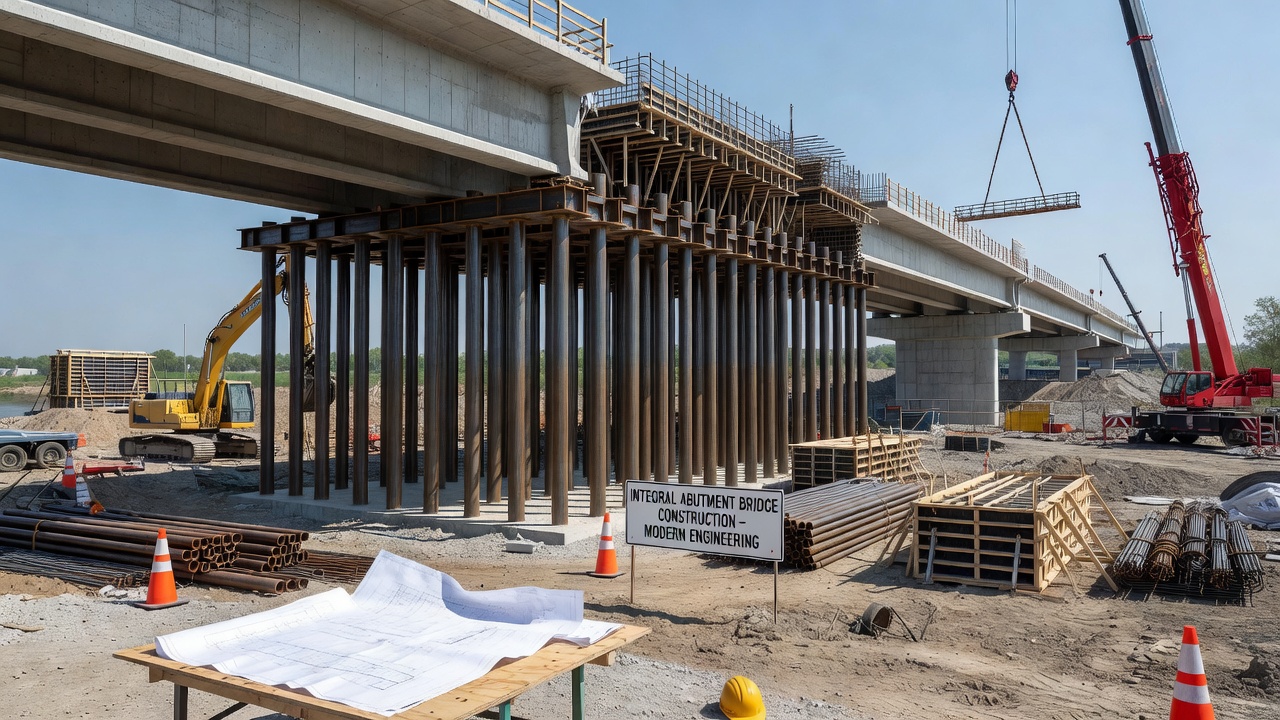
The integral abutment is rigidly connected to the bridge superstructure, with the deck and girders cast monolithically into the abutment cap. This eliminates expansion joints at the bridge ends — the single most common source of bridge deck deterioration. Integral abutments are supported on a single row of piles, typically steel H-piles or concrete piles, designed to flex and accommodate thermal expansion and contraction movements. The piles are designed for combined axial and lateral cyclic loading over the full thermal range of -20°F to +120°F. The superstructure absorbs soil forces from the backfill during thermal expansion, and according to FHWA research, the available capacity is typically far greater than required. Flowable fill must NOT be used as backfill behind integral abutments because it generates excessive passive pressures during thermal expansion. Approach slab settlement from undercompacted backfill is the most common maintenance issue. The maximum recommended length for integral abutment bridges varies by state but is typically 300 to 500 feet for steel girders and 600 to 800 feet for prestressed concrete girders.
The semi-integral abutment uses a pinned connection between the superstructure and substructure, allowing rotation while maintaining the connection. The approach slab is typically cast integrally with the superstructure, and an expansion joint is placed at the pavement end rather than at the bridge deck. This design is used for moderate-span bridges where some movement accommodation is needed but the full fixity of an integral connection is not desired. Semi-integral abutments use a single row of piles like integral abutments but avoid the moment transfer to the foundation.
The spill-through abutment, also called an open abutment, resembles a multi-column pier. The approach embankment extends on a slope below the bridge seat and between the supporting columns. Only the topmost portion of the embankment directly under the bridge seat is retained by the abutment cap. Spill-through abutments are cost-effective because the minimal horizontal load eliminates the need for a massive stem wall. They can also be converted to a pier for future bridge widening. The primary disadvantage is that fill tends to settle around columns due to poor compaction in confined spaces, and the exposed fore slope is susceptible to erosion and scour. Spill-through abutments are not suitable adjacent to streams due to scour susceptibility. Rock fill is sometimes used to counter erosion problems.
| Type | Key Features | Typical Use |
|---|---|---|
| Stub (Bank Pad) | Short backwall with independent wingwalls and spread or piled footings | Short spans, low embankments |
| Full-Retaining (Closed) | At base of embankment, retains entire slope | Reduced span length, tight right-of-way |
| Sill | At top of slope after embankment near final grade | Least expensive, easy constructability |
| Pile-Encased | Wall height to 10 ft maximum; skew limited to 15° fixed or 30° expansion | Local roads, tight right-of-way |
| MSE (Mechanically Stabilized Earth) | Precast concrete panels with metallic or polymeric soil reinforcing strips | Cost-effective, excellent seismic performance |
| GRS (Geosynthetic Reinforced Soil) | Concrete blocks with geosynthetic reinforcement layers per FHWA standards | Simple overpasses, not for severe flooding |
| Embedded | Wall extends deep into foundation soil using passive earth pressure for resistance | Medium-height structures, economical with piles |
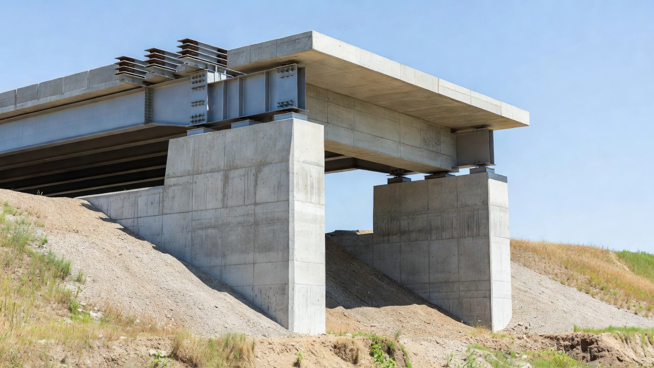
A bridge abutment assembly comprises several interconnected structural components, each with specific functions. The bridge seat or beam seat is the horizontal surface at the top of the abutment stem that directly supports the bridge superstructure. It distributes concentrated bearing forces from girder ends or bearings uniformly into the substructure. Bearing seat dimensions are determined by bearing plate geometry plus required edge distances, typically 6 inches minimum beyond the bearing edge. Cracking and spalling near bearing seat edges is a critical inspection finding because it directly affects load transfer.
The backwall is the vertical concrete wall at the end of the bridge deck that retains the approach roadway subbase, preventing soil from sliding onto the bridge seat. It also supports the approach slab and the expansion joint. Per Caltrans design practice, the backwall is designed for live load traffic impact forces, but these forces are used only for backwall design and are not transmitted to the abutment stem or foundation. Backwall height is typically 3 to 6 feet depending on approach slab configuration.
The breast wall or abutment stem is the main vertical structural element connecting the bridge seat to the foundation. It resists overturning, sliding, and bending from earth pressures and superstructure loads. Stem configurations vary by abutment type — solid wall for full-retaining abutments, cantilevered T-section for cantilever abutments, and buttressed for counterfort abutments. Stem thickness is governed by shear and flexural requirements at the base.
Wing walls retain the approach roadway embankment and guide traffic onto the bridge. They do not support superstructure loads (per FHWA BIRM). Geometrically, wing walls are classified as straight (extensions of the abutment wall), flared (at an acute angle to the bridge roadway), or U-wings (parallel to the bridge roadway, also called elephant-ear walls). Constructed as either integral (monolithic with abutment, included in substructure condition evaluation) or independent (separated by an expansion joint, treated as separate retaining walls). Wing wall slopes are typically a maximum of 2:1 (horizontal:vertical) with length determined by the allowable slope from the wing top elevation to the berm elevation plus an additional 2 feet for erosion control, rounded to the nearest 2-foot increment per WisDOT standards.
The footing or pile cap distributes abutment loads to the bearing stratum or pile group. Spread footings have a toe (front) and heel (back) section proportioned to keep resultant bearing pressures within allowable limits. Pile caps connect the pile heads to the abutment stem through reinforcement embedment. A shear key is sometimes provided at the footing base to increase passive earth pressure resistance. Approach slabs are 10 to 15 feet long pinned to the abutment at one end and resting on compacted fill at the other, providing a smooth transition and reducing differential settlement between the bridge and approach pavement.
Concrete cracking in abutments is categorized by cause and width. Structural cracks are typically vertical or diagonal, wider than 0.3 mm, and occur on the traffic face when applied loads exceed design limits or abnormal load transfer paths develop. These cracks may indicate overstress from settlement, overloading, or loss of support. Non-structural cracks are fine, irregular networks caused by temperature variation or concrete shrinkage, typically narrower than 0.3 mm. Shrinkage cracking is mitigated by placing chamfers (typically 1 foot) between the abutment and wing walls per FHWA design examples. Plastic cracking occurs during concrete curing as settlement or shrinkage cracks (BIRM classification).
Uniform settlement up to 0.3 m (1 foot) on small bridges may not produce visible structural distress. Differential settlement between substructure units causes opening of expansion joints, cracking of walls, and structural tipping — producing serious distress that requires immediate evaluation. Primary causes include soil bearing failure, consolidation of foundation soils under embankment weight, scour and undermining, mining subsidence, and solution cavities in limestone terrain. The bridge head bump — approach slab settlement at the bridge-embankment interface — creates vehicle impact loading, voids under bearing plates, and potential girder end cracking.
Rotational movement results from unsymmetrical settlements or lateral earth pressure exceeding design assumptions. Causes include undermining, scour, saturation of backfill reducing shear strength, bearing capacity failure, and erosion of retained fill. Detection methods include plumb bob checks, level surveys, measurement of clearance between beam ends and backwall, and observation of unusual crack patterns or spalls. Tip displacement exceeding 1:100 (horizontal:vertical) warrants structural evaluation.
Lateral sliding occurs when horizontal earth pressure exceeds the frictional resistance between the abutment base and foundation soil. Indicators include bearing displacement at the expansion joint, opened construction joints between wing wall and abutment, approach roadway settlement patterns, changes in distance between superstructure end and backwall, and clogged drainage systems. Causes include slope failure, seepage pressures, frost action, and time-dependent consolidation of the original foundation soil.
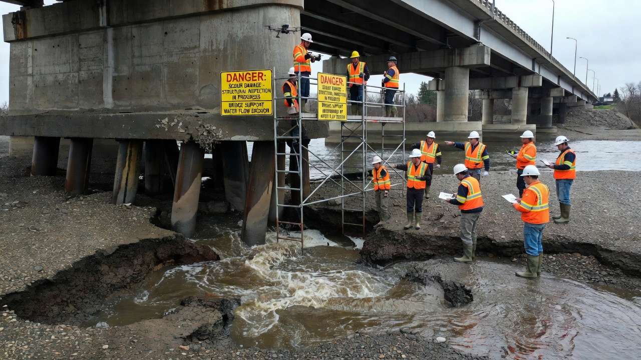
Scour is the removal of streambed material by the erosive action of flowing water around the abutment. It is the leading cause of bridge failure in the United States according to FHWA HEC-18 (Hydraulic Engineering Circular No. 18, Fifth Edition). Scour can remove supporting foundation material from beneath spread footings entirely, and silt can loosely fill scour holes offering no bearing capacity. Deep foundations (piles) may lose lateral support but retain vertical capacity if sufficient embedment remains.
Failed expansion joints allow rainwater infiltration onto the abutment bearing seat, accelerating concrete erosion and reinforcement corrosion. Clogged joints prevent thermal movement, inducing undesirable locked-in stresses in the substructure. Bearing failure presents as tilted bearing devices, voids under bearing plates, premature elastomeric aging, or bearing seat cracking — particularly critical where concrete beams bear directly on abutment seats without bearing devices.
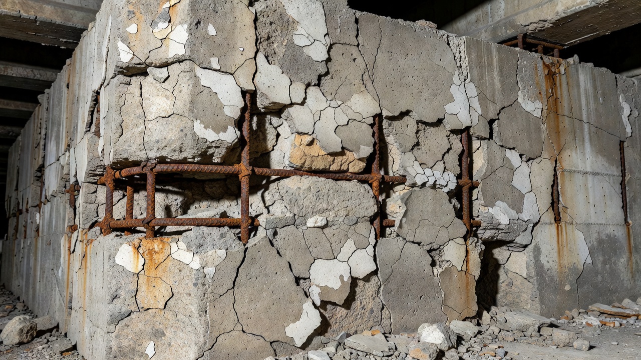
Spalling and delamination begin as surface scaling from salt erosion in coastal or saline environments followed by subsurface separation detectable by chain drag or hammer sounding. Once the protective concrete cover is breached, reinforcement corrosion begins. The corrosion products (rust) occupy approximately 2 to 4 times the volume of the original steel, generating expansive tensile stresses that further crack and spall the concrete — creating a self-accelerating corrosion-crack-corrosion cycle. Efflorescence — white crystalline calcium carbonate deposits on the concrete surface — indicates active water migration through cracks or porous concrete. Discoloration under weep holes can indicate functioning drainage. Freeze-thaw damage from repeated expansion-contraction cycles is particularly damaging in northern climates where frost heave effects can displace abutments.
The Specifications for the National Bridge Inventory (SNBI), published by FHWA in March 2022 (FHWA-HIF-22-017), establishes standardized condition rating requirements for all bridges on public roads. The abutment condition is rated as part of the substructure evaluation under item B.C.03 Substructure Condition Rating.
The SNBI defines a ten-point condition rating scale from 0 to 9 for component-level assessment:
| Code | Label | Condition Description |
|---|---|---|
| 9 | Excellent | Isolated inherent defects only |
| 8 | Very Good | Some inherent defects present |
| 7 | Good | Some minor defects noted |
| 6 | Satisfactory | Widespread minor or isolated moderate defects |
| 5 | Fair | Some moderate defects; strength and performance not affected |
| 4 | Poor | Widespread moderate or isolated major defects; strength and/or performance affected |
| 3 | Serious | Major defects; strength and/or performance seriously affected; may necessitate load restrictions |
| 2 | Critical | Major defects; component severely compromised; typically requires load restriction and corrective action |
| 1 | Imminent Failure | Major defects; component failed or failure imminent; bridge closed to traffic |
| 0 | Failed | Component has failed beyond corrective action; bridge closed |
Ratings of 4 or below are classified as Poor by federal standards. Any component rating of 3 or below automatically triggers mandatory documentation including defect description, immediate action taken, and photographic evidence. Critical findings can also be triggered by extreme scour (B.C.11 ≤ 3), observed settlement or movement, or inspector judgment.
For bridges on the National Highway System (NHS), SNBI mandates element-level inspection per the AASHTO Manual for Bridge Element Inspection (MBEI). The element-level system uses four condition states:
| State | Label | Description |
|---|---|---|
| CS1 | Good | No defects. As-built or as-rehabilitated condition. |
| CS2 | Fair | Minor defects — hairline cracks, minor surface rust, minor spalling. Structural capacity intact. |
| CS3 | Poor | Moderate defects — active corrosion, measurable section loss, open cracks, visible spalling. Capacity intact but deterioration progressing. |
| CS4 | Severe | Major defects affecting structural capacity — significant section loss, cracked/broken members, large deformations. Triggers structural review. |
The primary element for abutments is Element 215 (Concrete Abutment), with quantities measured in square feet of exposed surface area. For spill-through abutments with columns, Element 205 (Reinforced Concrete Column) may also be used. The sum of CS1 + CS2 + CS3 + CS4 quantities must equal the total element quantity (validation rule).
Additional SNBI condition items affecting abutments include B.C.07 Bridge Bearings Condition Rating, B.C.08 Bridge Joints Condition Rating, B.C.09 Channel Condition Rating (bank stability, debris, alignment), B.C.10 Channel Protection Condition Rating, and B.C.11 Scour Condition Rating (physical evidence of scour at foundation).
Bridge abutment inspection follows the procedures outlined in the FHWA Bridge Inspector’s Reference Manual (BIRM) and NBIS regulations (23 CFR 650 Subpart C). The standard inspection interval is 24 months maximum, extendable to 48 or 72 months using risk-based methods (Method 1 or 2 per NBIS).
Visual inspection is the most fundamental method. Inspectors examine bearing seats for cracking and spalling near edges, backwalls for cracking and movement, construction joints between backwall and stem, wing wall alignment and separation, and approach slab settlement conditions. Debris accumulation and standing water on bearing seats are documented. Areas exposed to roadway drainage — particularly below the deck-to-backwall joint — receive heightened scrutiny. All spalls, exposed reinforcement, section loss, and collision damage are photographed and measured.
Sounding is performed using a chain drag — a chain is dragged across the concrete surface. A hollow or drummy sound indicates delaminated concrete, while a solid ringing sound indicates sound concrete. The chain drag method is the standard FHWA protocol for detecting moderate to severe delamination in concrete bridge components. Results are validated through visual survey of identified spall locations and extent. Hammer sounding uses a hammer tap on the concrete surface — clear ringing equals sound concrete, dull hollow indicates subsurface delamination.
Nondestructive testing (NDT) methods are used for deeper evaluation when visual and sounding methods are insufficient. Ultrasonic testing (UT) measures steel thickness and detects internal flaws, coded SNBI I01. Ground-penetrating radar (GPR) locates reinforcement, measures concrete cover, and detects voids, coded I02. Infrared thermography (IR) detects delamination through surface temperature differentials, coded I03. Impact echo (IE) measures concrete thickness and detects internal voids and flaws, coded I05. Electromagnetic methods map reinforcement location and corrosion potential, coded I06. Rebound hammer estimates concrete compressive strength, coded I07.
Corrosion assessment uses half-cell potential mapping to identify active corrosion areas in reinforced concrete, chloride content testing from concrete powder samples collected at incremental depths (typically 0-1 inch, 1-2 inches, 2-3 inches), and concrete resistivity measurement to assess corrosion rate potential. Petrographic examination per ASTM C856 identifies material degradation mechanisms including alkali-silica reaction (ASR), delayed ettringite formation (DEF), and freeze-thaw damage.
Movement monitoring uses level surveys for settlement measurement, crack width monitoring with tell-tales or mechanical crack gauges for active movement detection, plumb bobs and total station surveys for lateral and rotational displacement, inclinometers for tilt measurement, and direct measurement of bearing travel for expansion joint functionality assessment.
Scour at bridge abutments is evaluated using the methods in FHWA HEC-18 (Evaluating Scour at Bridges, Fifth Edition) and HEC-20 (Stream Stability at Highway Structures). Total scour comprises four components: long-term degradation (streambed elevation change over decades), contraction scour (removal of material from the channel due to flow constriction at the bridge), local scour at abutments (erosive action of flow accelerating around the abutment nose), and lateral stream migration (channel shifting that can undermine abutment foundations).
The flow field around an abutment creates a horseshoe vortex at the abutment base (similar to piers but with embankment interaction), with flow separation at the abutment nose generating a turbulent wake. Scour conditions are classified as clear-water scour (no sediment transport from upstream, occurs when velocity exceeds critical velocity for bed material) or live-bed scour (sediment transported from upstream, scour hole reaches equilibrium when sediment inflow equals outflow).
Froehlich’s Abutment Scour Equation evaluates scour depth for abutments with spill-through slope ≤ 90°:
ys/y₁ = 2.27K₁K₂(L’/y₁)^0.43 × Fr₁^0.61 + 1
Where ys = scour depth, y₁ = flow depth, L’ = effective abutment length, Fr₁ = Froude number, K₁ = shape factor (1.0 for vertical, 0.82 for vertical with wing walls, 0.55 for spill-through), and K₂ = skew factor. The HIRE equation is used for abutments extending into the channel where L/y₁ > 25.
The calculated total scour depth is compared to the foundation bottom elevation. If scour reaches below the foundation — the bridge is scour critical. Spread footings are more vulnerable since once undermined, rapid failure is possible. Deep foundations lose lateral support but may retain vertical capacity if sufficient embedment remains.
The Scour Vulnerability Classification (SNBI B.AP.03) uses codes A (Scour Stable — standard foundation designed to resist scour), B (Scour Stable — protection from installed countermeasures), C (Scour Stable — screening analysis confirms low risk), D (Scour Critical — hydraulic calculations show vulnerable foundations, monitoring plan required), and U (Unknown — foundation type unknown, vulnerability undetermined). Bridges coded D or U require a Plan of Action (POA) per FHWA requirements.
Scour Condition Rating (SNBI B.C.11) is rated on the 0-9 scale based on observed physical evidence at the foundation. Scour monitoring inspections (SNBI Inspection Type Code 9) are triggered by storm events per the POA, including remote electronic streambed elevation readings and post-flood inspections wherever water reached the exterior girder web.
Abutment drainage is critical for structural performance. Water buildup behind the abutment creates horizontal hydrostatic pressure that directly increases overturning and sliding demands. Saturated backfill increases effective earth pressure and reduces soil shear strength, increasing the lateral load on the stem. Poor drainage accelerates freeze-thaw damage in cold climates.
Weepholes are typically 100 mm (4 inches) in diameter and placed at regular intervals along the abutment stem to relieve hydrostatic pressure. They should be checked for clear flow during inspection — animal nests and debris frequently block these openings. Discoloration and staining under weep holes indicates functioning drainage (BIRM).
Geocomposite drainage mats placed behind the abutment wall use a three-dimensional core material to conduct water vertically to collection pipes, with geotextile filter fabric to prevent soil migration. Subsurface drainage pipes run parallel to the rear face of the abutment stem, sloped to drain water laterally out at the abutment ends, embedded in a granular drainage blanket.
Slope pavement (concrete or asphalt protection on the embankment in front of the abutment) prevents surface water infiltration and erosion. Filter fabric is placed behind weep holes and precast concrete panels in MSE walls to separate backfill from drainage aggregate, preventing clogging while allowing water flow.
Drainage system failures identified during inspection include pavement settlement along the approach, damp or saturated areas on the abutment face, efflorescence deposits, blocked weep holes, and deteriorated slope pavement. Clogged drains are the most common drainage deficiency found during routine bridge inspection.
Non-structural cracks narrower than 0.3 mm are sealed using flexible surface sealants — polyurethane or silicone formulations that accommodate minor movement. Structural cracks wider than 0.3 mm requiring full strength restoration are repaired with epoxy injection using two-component epoxy resins. The process involves cleaning and drying the crack, installing injection ports at regular intervals along the crack length, sealing the crack surface between ports with epoxy paste, and injecting low-viscosity epoxy under controlled pressure. The restored bond can achieve tensile strength equivalent to the parent concrete.
Pneumatically applied mortar — shotcrete (dry-mix, water added at nozzle) or gunite (wet-mix) — is used for structural section restoration of spalled or deteriorated abutment surfaces. Typical specified compressive strength is 28 to 35 MPa (4,000 to 5,000 psi) with a minimum application thickness of 1.5 to 2 inches for structural repairs. Surface preparation using hydrodemolition (10,000 to 20,000 psi water jet) or sandblasting is required to ensure bond between the existing concrete and shotcrete. Latex-modified concrete (LMC), silica fume modified concrete (SFMC), or polyester polymer concrete (PPC) are used for patching with a minimum 14-day cure time.
Carbon fiber reinforced polymer (CFRP) systems are externally bonded to abutment surfaces for flexural and shear strengthening following the AASHTO Guide Specifications for Design of Externally Bonded FRP Systems. Carbon fiber sheets are pre-impregnated with epoxy resin and laminated onto the prepared concrete surface. CFRP systems are used for seismic retrofit of abutment walls, flexural capacity restoration of beam ends, and shear strengthening of pier caps and columns. The INDOT fiber wrap program has standardized CFRP application for beam end repair.
Underpinning extends existing foundations to deeper, more competent bearing strata when abutment settlement or scour has compromised the original foundation. Methods include pit underpinning (excavating sections beneath the existing footing in controlled sequences and pouring new concrete) and pile underpinning (installing micropiles or driven piles on either side of the existing footing and connecting with new grade beams or needle beams). Micropiles — small-diameter (6 to 12 inch) drilled and grouted piles — require minimal access and are ideal for confined work zones under active bridges.
Concrete jacketing places reinforced concrete or steel jackets around existing abutment stems or columns. Minimum jacket thickness is typically 4 to 6 inches with new longitudinal and transverse reinforcement. Steel jackets — welded steel plate encasement filled with grout — are common for seismic retrofitting. Jacketing increases flexural and shear capacity, ductility, and confinement.
Soil nailing installs closely spaced passive reinforcing bars (nails, typically #6 to #11 Grade 60) grouted into drilled holes at 4 to 6 foot spacing into existing slopes or embankments behind abutments. A shotcrete facing with welded wire mesh is applied to the slope surface. Used for stabilizing slope failures, repairing abutment embankment slides, and steepening failed slopes.
Tieback anchors are prestressed ground anchors using high-strength steel strands or bars grouted into stable soil or rock behind the abutment. Components include the anchor bond zone (grouted into rock or competent soil), free stressing length, and anchor head with trumpet at the wall face. Design loads range from 50 to 500+ kips per anchor. Double corrosion protection per PTI (Post-Tensioning Institute) Recommendations includes sacrificial steel thickness, epoxy coating, and grout encapsulation. Proof testing to 133% of design load is standard.
Grouting includes compaction grouting (low-slump mortar injected to densify loose soils behind or beneath abutments), permeation grouting (cementitious or chemical grout fills voids in soil or rock), and contact grouting (fills voids between abutment backwall and retained soil). Used for settlement remediation, scour void filling, crack repair, and soil improvement.
Excavation and replacement of poorly compacted backfill with select granular material compacted to >96% density per modified Proctor is the primary approach slab rehabilitation method. Drainage trenches are installed to prevent water accumulation. The slab is replaced if cracked or excessively settled. Mechanical stabilization of the subbase extends the transition zone and reduces the bridge head bump recurrence.
TarmacView provides comprehensive bridge inspection solutions including abutment condition assessment, scour evaluation, and SNBI-compliant reporting. Contact our team of experienced bridge engineers.
Bridge bearings are critical load-transfer devices at abutments and piers that transmit superstructure forces to the substructure while accommodating thermal mo...
A bridge pier is an intermediate vertical support structure between abutments that transfers superstructure loads to the foundation. Multi-column bents, wall pi...
The bridge deck is the uppermost structural element of a bridge, directly supporting traffic loads and providing the riding surface. Deck condition — cracking, ...