What is an Aeronautical Ground Light (AGL)?
Aeronautical Ground Light (AGL) – Comprehensive Glossary and Technical Guide
Aeronautical Ground Lights (AGL) are foundational to airfield safety and operational efficiency, providing standardized visual cues for pilots and ground crews during all phases of aircraft movement. This glossary page delivers a thorough reference to AGL concepts, system components, technical standards, regulatory context, and emerging technologies.
Table of Contents
- Aeronautical Ground Light (AGL)
- Aeronautical Ground Lighting (AGL) System
- Runway Lighting
- Taxiway Lighting
- Approach Lighting System (ALS)
- Visual Guidance Indicators: PAPI & VASI
- Power Supply and Control Systems
- Ancillary Equipment and Signs
- Regulatory and Standardization Framework
- Operational and Technical Requirements
- Compliance and Safety Standards
- Emerging Technologies in AGL
- Photometric Testing and Maintenance
- References
1. Aeronautical Ground Light (AGL)
Definition:
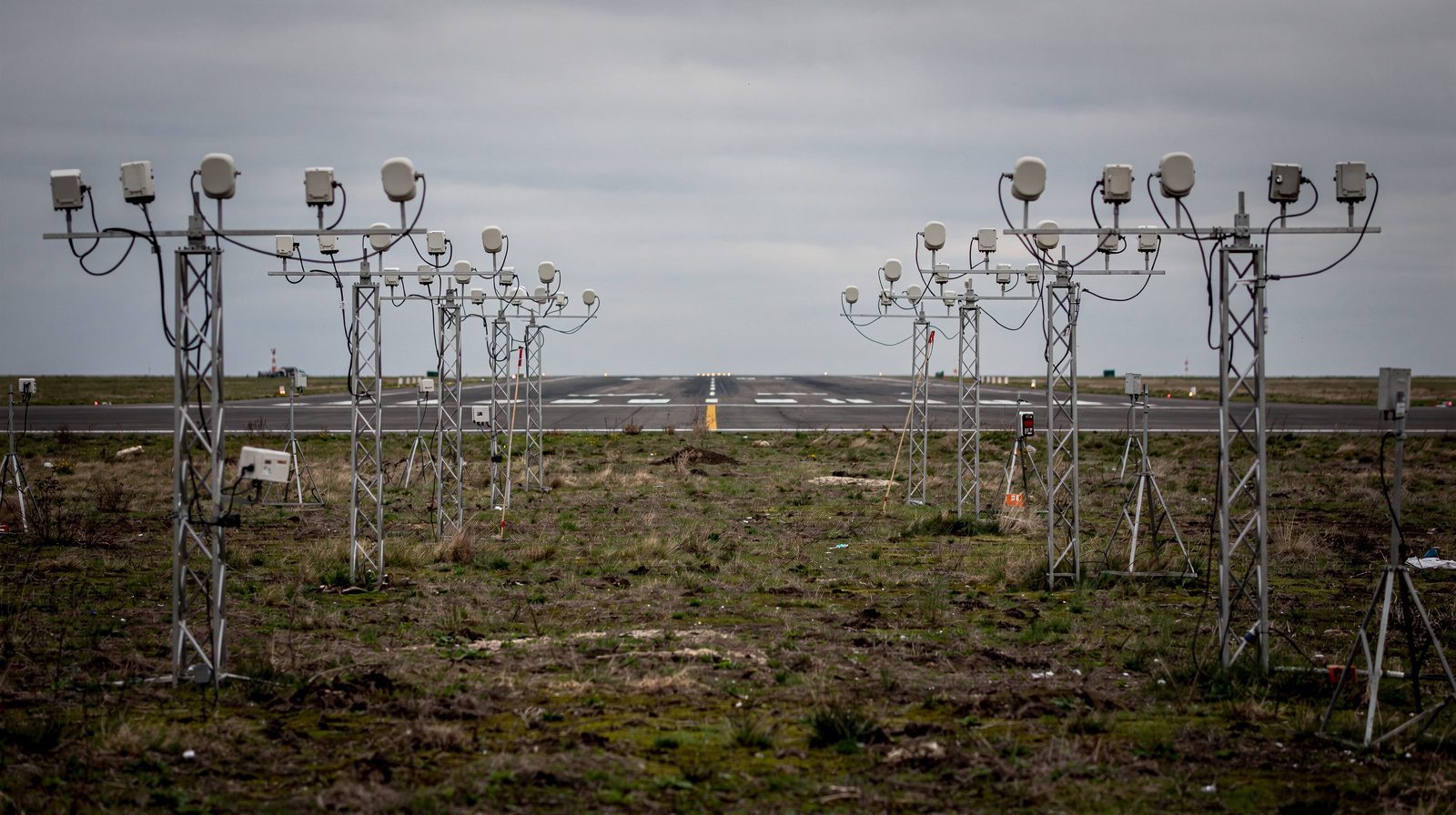
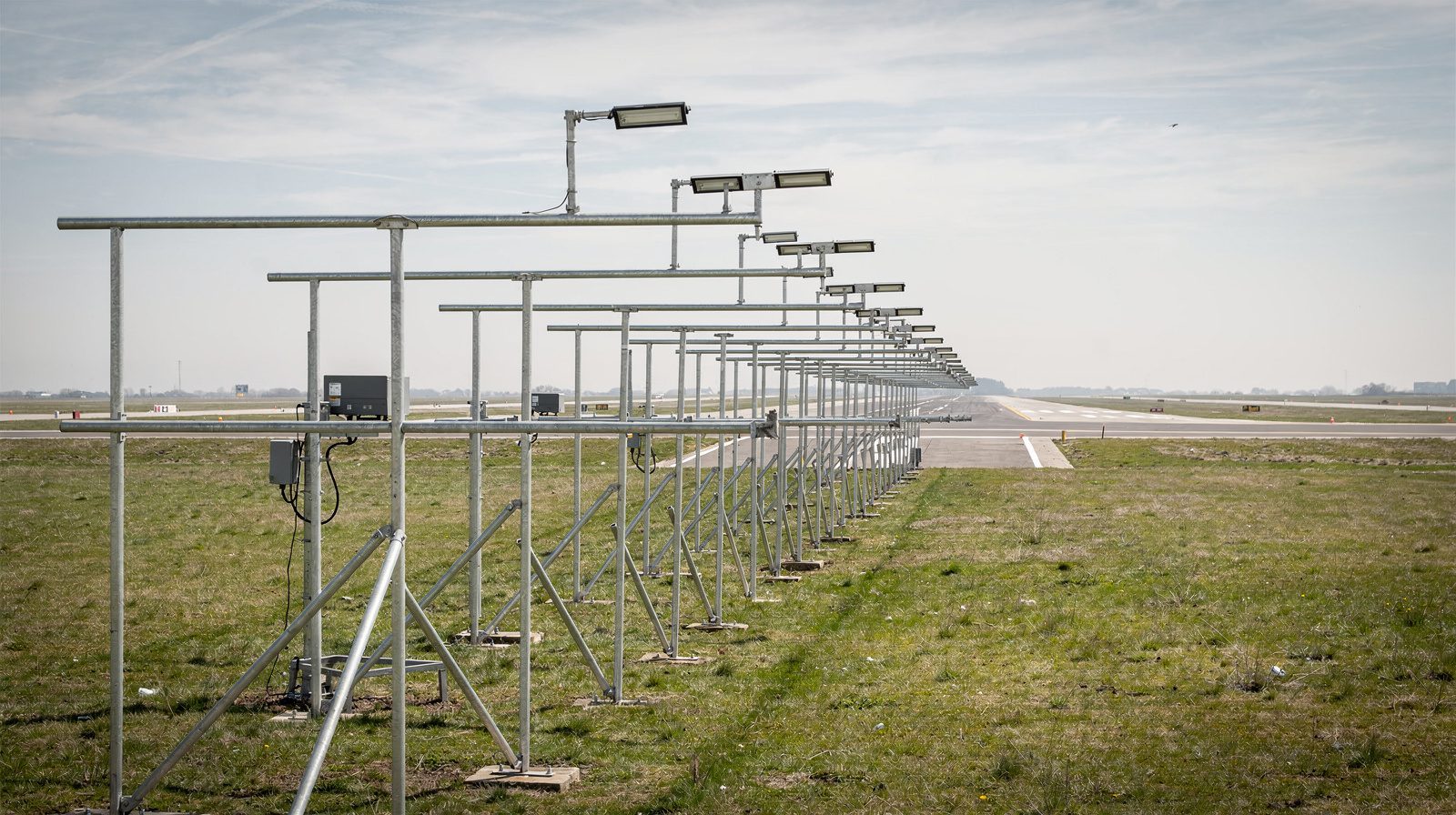
An Aeronautical Ground Light is any light installed at an aerodrome or along an air route, as an aid to air navigation, excluding lights on aircraft. Their primary function is to provide clear, standardized visual guidance to pilots and ground personnel in all visibility and weather conditions.
- Where used: Runways, taxiways, aprons, approach/departure paths, heliports, and air routes.
- Regulation: ICAO Annex 14 is the global standard for AGL requirements.
ICAO Annex 14
2. Aeronautical Ground Lighting (AGL) System
A comprehensive AGL System comprises all lights, power systems, control equipment, and supporting infrastructure designed to ensure the safe and efficient movement of aircraft and vehicles on the ground.
Typical system components:
- Runway and taxiway lighting
- Approach lighting systems
- Visual guidance indicators (PAPI, VASI)
- Power supply (CCR, series circuits)
- Control and monitoring systems
- Illuminated signs and apron floodlighting
Purpose: To provide unambiguous visual information under all operational scenarios, supporting both visual and instrument flight rules (VFR and IFR).
3. Runway Lighting
Runway lighting systems define the runway environment and assist pilots during approach, landing, takeoff, and taxi operations, especially in reduced visibility.
Runway Edge Lights
- Description: Elevated or inset white lights outlining the runway’s edges.
- Color: White, with yellow replacing white in the caution zone near the runway end on instrument runways.
- Spacing: No more than 60 meters (200 feet).
- Reference: FAA AIM 2-1-2
Runway Centerline Lights
- Description: Flush lights along the runway centerline.
- Color: White, shifting to red and white, then all red as the runway end approaches (per ICAO/FAA standards).
- Use: Essential for low-visibility operations and precision approaches.
Threshold Lights
- Description: Green lights marking the runway threshold, visible to arriving aircraft.
Runway End Lights
- Description: Red lights marking the physical runway end, visible to departing aircraft.
Touchdown Zone Lights (TDZL)
- Description: Rows of white lights extending from the threshold, marking the touchdown area for precision landings.
Runway End Identifier Lights (REILs)
- Description: Synchronized flashing white lights at each side of the runway threshold, enhancing threshold visibility.
4. Taxiway Lighting
Taxiway lighting systems guide aircraft between runways, aprons, and terminals.
Taxiway Edge Lights
- Description: Elevated blue lights outlining taxiway edges.
- Purpose: Define taxiway boundaries during night or low-visibility.
Taxiway Centerline Lights
- Description: Flush green lights along taxiway centerlines, critical at complex intersections and high-speed exits.
Lead-On/Lead-Off Lights
- Description: Alternating green/yellow lights for directing aircraft onto or off runways.
Stop Bar Lights
- Description: Red in-pavement lights at runway holding positions, remotely switched by ATC for runway incursion prevention.
Runway Guard Lights
Description: Flashing yellow lights at runway/taxiway intersections to warn of imminent runway entry.
Reference: Skybrary: Taxiway Lighting
5. Approach Lighting System (ALS)
Approach Lighting Systems provide visual guidance for landing by extending light bars and flashers from the runway threshold into the approach area.
- Types:
- ALSF-1 / ALSF-2 (high-intensity, precision approaches)
- MALSR (medium-intensity with alignment lights)
- ODALS (omnidirectional for non-precision runways)
- Length: Typically 720–900 meters (2,400–3,000 feet)
- Reference: FAA AIM 2-1-2
6. Visual Guidance Indicators
Precision Approach Path Indicator (PAPI)
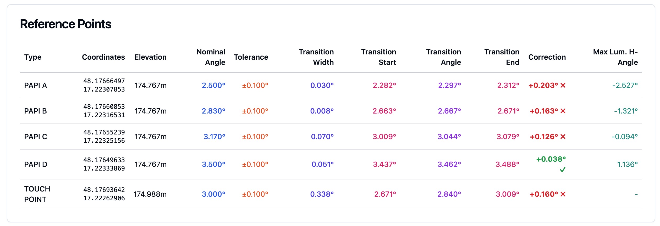
- Description: A row of two or four light units, each showing red or white based on the approach angle.
- Interpretation:
- 4 white: Too high
- 3 white/1 red: Slightly high
- 2 white/2 red: Correct path
- 1 white/3 red: Slightly low
- 4 red: Too low
- Reference: FAA PAPI Guide
Visual Approach Slope Indicator (VASI)
- Description: Two or three light bars placed beside the runway, indicating approach slope by color combination.
- Interpretation:
- Red over white: On glide path
- White over white: Too high
- Red over red: Too low
7. Power Supply and Control Systems
Constant Current Regulator (CCR)
- Purpose: Maintains constant current in AGL series circuits, ensuring uniform light output.
- Standard: IEC 61822
Series Circuit Wiring
- Description: AGL fixtures are connected in series, enhancing system reliability.
Isolating Transformers
- Function: Electrically isolate each fixture for safety and allow individual replacement.
Control and Monitoring Systems
- Description: Centralized systems (like ALCMS) provide remote switching, dimming, and monitoring.
- Reference: FAA AC 150/5345-56B
8. Ancillary Equipment and Signs
Illuminated Airport Signs
- Types: Mandatory instruction (red), direction/information (yellow/black), location (black/yellow).
- Standards: FAA AC 150/5340-18H
Apron Floodlighting
- Description: High-intensity lights for apron/stand illumination, minimizing glare to air traffic control and pilots.
9. Regulatory and Standardization Framework
ICAO
- Role: Sets global standards through Annex 14 and supporting manuals.
- Reference: ICAO Annex 14
FAA
- Role: U.S. standards via AIM, Advisory Circulars (e.g., AC 150/5340 series).
- Reference: FAA AIM Chapter 2
IEC
- Role: Publishes international electrical standards for AGL equipment.
- Reference: IEC Wikipedia
CENELEC
- Role: European standardization for AGL systems.
- Reference: CENELEC Wikipedia
10. Operational and Technical Requirements
AGL systems must deliver high reliability, redundancy, and compliance. Requirements include:
- Minimum light intensity and color consistency
- Correct placement, spacing, and orientation
- Redundancy in power and control
- Environmental resilience (weather, temperature, vibration)
- Maintenance accessibility and safety
11. Compliance and Safety Standards
Compliance is mandatory for airport certification and safe operation. Key points:
- Regular inspection and maintenance schedules
- Photometric testing for intensity and coverage
- Adherence to ICAO, FAA, IEC, and CENELEC specifications
- Documentation and traceability of changes and repairs
12. Emerging Technologies in AGL
LED Lighting
- Energy-efficient, long-lasting, and increasingly standard for new installations.
Intelligent Airfield Lighting
- Integrated sensors, adaptive control, and diagnostics for optimized operation.
A-SMGCS (Advanced Surface Movement Guidance and Control System)
- Integrates AGL with radar, multilateration, and control systems for real-time surface management and safety.
13. Photometric Testing and Maintenance
- Routine photometric testing ensures lights meet intensity and color requirements.
- Maintenance includes cleaning lenses, verifying alignment, replacing failed units, and checking electrical connections.
- Regulations require periodic audits and reporting.
14. References
- ICAO Annex 14
- FAA Aeronautical Information Manual (AIM)
- IEC – International Electrotechnical Commission
- CENELEC – European Committee for Electrotechnical Standardization
- Skybrary: Taxiway Lighting
Aeronautical ground lighting continues to evolve, driven by the need for greater efficiency, safety, and automation. Adhering to international standards ensures interoperability and global aviation safety. For in-depth regulations, always consult the latest official documents from ICAO, FAA, IEC, and CENELEC.
Frequently Asked Questions
- What is an Aeronautical Ground Light (AGL)?
- An Aeronautical Ground Light is any light installed at an aerodrome or along air routes, designed to aid air navigation by providing visual guidance for aircraft movements, excluding lights displayed on aircraft themselves. These lights are mandated and standardized by organizations like ICAO and FAA.
- What are the primary types of AGL at an airport?
- The main types include runway lighting (edge, centerline, threshold, end, touchdown zone, and REILs), taxiway lighting (edge, centerline, stop bars, guard lights), approach lighting systems (ALS), visual guidance indicators (PAPI, VASI), illuminated signs, and apron floodlighting.
- Who sets the standards for AGL?
- The International Civil Aviation Organization (ICAO), Federal Aviation Administration (FAA), International Electrotechnical Commission (IEC), and European Committee for Electrotechnical Standardization (CENELEC) set global and regional standards for AGL design, performance, and operation.
- What is the difference between PAPI and VASI?
- PAPI (Precision Approach Path Indicator) uses a row of two or four lights to provide precise visual glide path information, while VASI (Visual Approach Slope Indicator) uses two or three light bars. Both guide pilots on correct approach angles, but PAPI is more common at precision instrument runways.
- How is AGL powered and controlled?
- AGL systems are typically powered by series circuits regulated by constant current regulators (CCR), with power supply redundancy and isolating transformers for safety. Control and monitoring are managed through centralized systems like ALCMS, enabling remote switching, dimming, and fault detection.
- Are LED lights used in AGL?
- Yes, airports increasingly use LED technology in AGL for improved energy efficiency, longer service life, and better performance, especially in low-visibility operations. LEDs are now standard for many new installations and upgrades.
- Where can I find the official ICAO standards for AGL?
- Official ICAO standards for aeronautical ground lighting are published in Annex 14 to the Convention on International Civil Aviation. For more information, visit the [ICAO Annex 14 page](https://www.icao.int/safety/airnavigation/Aerodromes/Pages/Annex-14.aspx).
This is a reference entry. TarmacView provides drone inspection services and doesn't sell the equipment or materials described in this glossary.