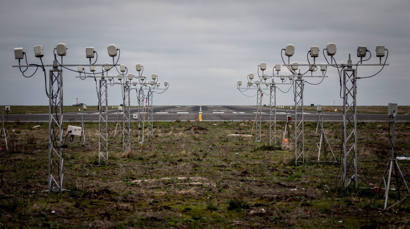
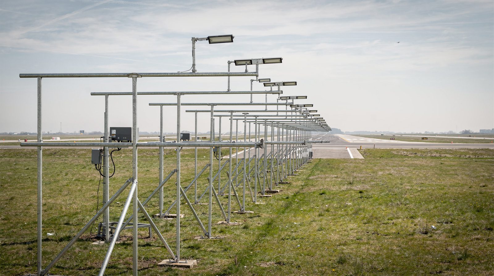
What is Approach Lighting?
Definition
Approach lighting system (ALS): the aeronautical ground lights installed before a runway threshold, on and around the extended centreline, to show the crew where the runway is before the runway lights themselves can be seen.
In one line: white lights on the extended centreline, one or more crossbars at set distances, and on the lowest-visibility runways a pair of red side rows close to the threshold. In the EU the patterns are certification specifications in CS-ADR-DSN (M.625 to M.635) under Regulation (EU) No 139/2014, and they follow ICAO Annex 14 Volume I section 5.3.4. The UK publishes its specifications in CAP 168 and NATO in STANAG 3316. The FAA has its own family of systems in AC 150/5340-30J and Order JO 6850.2. The two families are laid out differently but do the same job.
The system starts at the threshold and works outwards. It is not part of the runway lighting, which begins at the threshold lights and runs down the pavement, and it is not a glide slope aid, which is the job of PAPI.
What the pattern gives the pilot
- Alignment: the centreline row shows the runway axis, so lateral error is seen as an angle rather than guessed.
- Roll: crossbars and side rows give a horizon reference in cloud or haze.
- Distance: the crossbar 300 m out (the decision bar in FAA terms, the 1,000 ft bar) tells the crew how far the threshold is.
- Direction of travel: sequenced flashing lights run outward-to-inward toward the threshold, twice per second, so the eye is led the right way.
Because a working ALS lets a crew see the runway environment earlier, the published visibility minimums for that runway are lower than they would be without it. When part of the system is unserviceable the minimums go up, which is why an ALS outage is always a NOTAM item.
ICAO configurations
CS-ADR-DSN and ICAO define three patterns, each a step up in length, density and lighting for a lower category of precision approach.
Simple approach lighting system. For non-precision and non-instrument runways. A single row of fixed lights on the extended centreline, at least 420 m long, spaced 60 m (30 m is allowed for better guidance), with one crossbar 18 m or 30 m long at 300 m from the threshold. The colour is left to the state, as long as the system cannot be confused with other ground lights.
Precision approach category I system. Centreline lights at 30 m spacing running 900 m out wherever the terrain allows, with a 30 m crossbar at 300 m. Where the centreline is built from single lights rather than barrettes, further crossbars go in at 150, 450, 600 and 750 m so the pattern still reads as a plane. All lights are fixed variable white.
Precision approach category II and III system. The same 900 m centreline and crossbar layout as CAT I beyond 300 m, but the inner 300 m is denser: the centreline becomes barrettes, crossbars sit at 150 m and 300 m, and two rows of red side row barrettes run from the threshold out to 270 m at the same lateral spacing as the touchdown zone lights. This inner section is what a crew sees at a CAT II or III decision height, so it is where the serviceability limits are tightest.
FAA configurations
The FAA systems are named by intensity and by whether they carry sequenced flashers. Order JO 6850.2C splits them into two families: ALSF-2 is the high-intensity system for CAT II and III, and SSALR, MALS, MALSF and MALSR are medium-intensity systems for CAT I. All of them except ODALS use white centreline light bars and a crossbar at 1,000 ft.
- ALSF-2: high intensity, 2,400 ft, centreline bars every 100 ft from 100 ft out, crossbars at 500 ft and 1,000 ft, red side row bars of three lights either side of the centreline over the inner 900 ft, and 15 sequenced flashers on the outer bars. The FAA system for CAT II and III. See ALSF for the ALSF family in detail.
- SSALR: simplified short approach lighting system with runway alignment indicator lights. Medium intensity, 2,400 ft, centreline bars every 200 ft out to 1,400 ft, a crossbar at 1,000 ft, then five RAIL flashers every 200 ft out to 2,400 ft. It is not a system of its own but a mode of an ALSF-2/SSALR installation, selected in favourable weather.
- MALSR: a MALS plus RAIL, medium intensity, with the same 2,400 ft layout as SSALR. The FAA’s CAT I system where no ALSF-2 is installed. See MALSR .
- MALSF: medium intensity, 1,400 ft, centreline bars every 200 ft, with three sequenced flashers on the outer bars instead of RAIL. For non-precision runways where the approach area makes the runway hard to pick out.
- ODALS: seven omnidirectional flashers, five on the centreline every 300 ft out to 1,500 ft and one either side of the threshold, for non-precision runways. The FAA no longer installs it as a new facility. Not a centreline system in the ICAO sense.
The ALSF-1 appears in the approach lighting drawings of the FAA AIM (Figure 2-1-1), with red bars near the threshold and no side rows, but the current FAA order and advisory circular give no dimensions for it.
Specifications
What an approach lighting system is specified to
The dimensions, colours and limits an ALS is built and kept to, with the clause each one comes from.
Centre line row from the threshold out along the extended centre line, shortened only where the site does not allow the full run.
Minimum centre line length for a simple approach lighting system on a non-precision or non-instrument runway.
Longitudinal interval between centre line lights or barrettes, the innermost 30 m from the threshold.
Longitudinal interval on a simple system, with the closer spacing permitted where better guidance is wanted.
Row of lights at right angles to the centre line and bisected by it, marking 300 m. Gaps either side of the centre line are kept to a minimum.
Required where the centre line is made of single lights rather than barrettes.
Crossbars in the inner 300 m that make up the CAT II and III pattern with the side rows.
Two rows of red barrettes either side of the centre line from the threshold outward, at the lateral spacing of the touchdown zone lights.
Minimum length of a centre line or side row barrette, and the largest interval between the lights that form it.
Centre line and crossbar lights on precision systems, and the side rows that mark the CAT II and III inner section.
Where installed, the flashing lights fire in sequence from the outermost light toward the threshold.
Approach lights are not mounted below a set downward gradient from the threshold, so the pattern does not give a false picture of the ground.
Nothing protrudes through the plane of the approach lights close to the centre line, except an ILS or MLS azimuth antenna.
Approach centre line and crossbar lights follow their own isocandela diagram, separate from the runway lights. The values are printed on the diagram itself.
Approach lights and their supports break away on impact. Beyond 300 m, only the top 12 m of a taller support, or the part above surrounding non-frangible objects, has to.
Share of approach lights serviceable during CAT II or III operations, by section. The basic pattern must not change, and no two adjacent lights may be out except two in a barrette or crossbar.
Share of approach lights serviceable during CAT I operations. No unserviceable light next to another unless the spacing is much closer than required.
Distance the system reaches from the threshold into the approach area, by runway type.
Interval between the centre line light bars along the system.
Visual examples
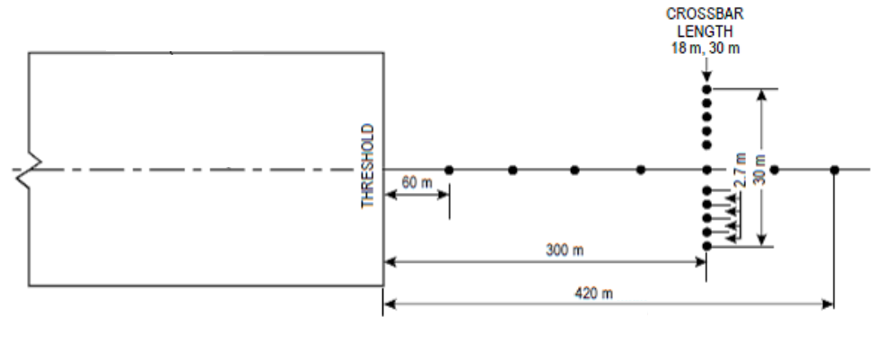
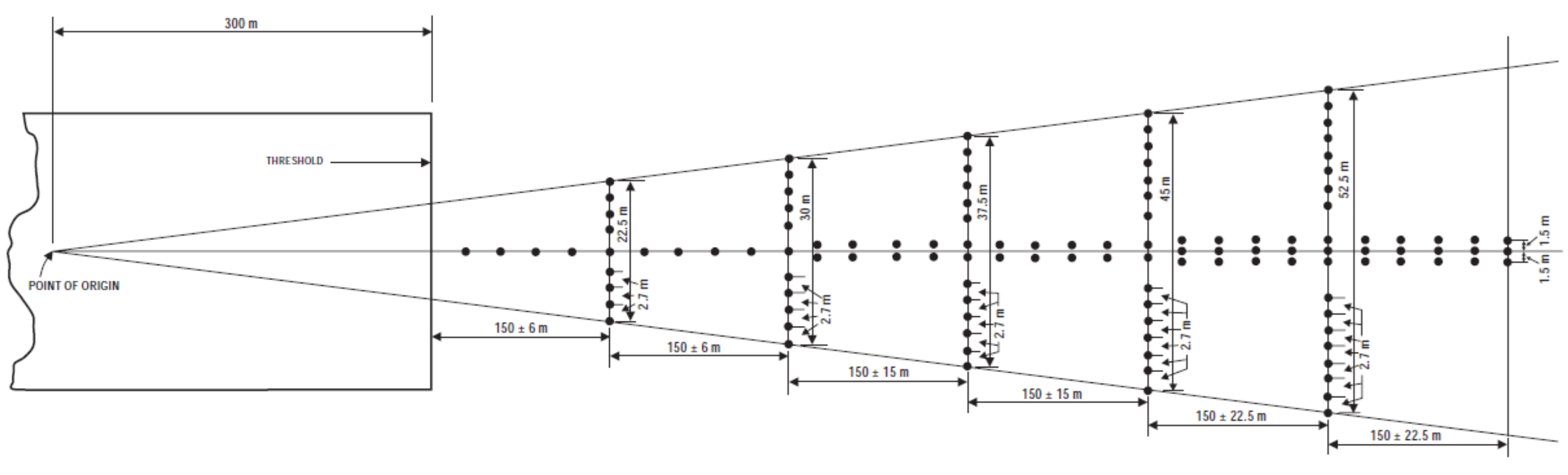
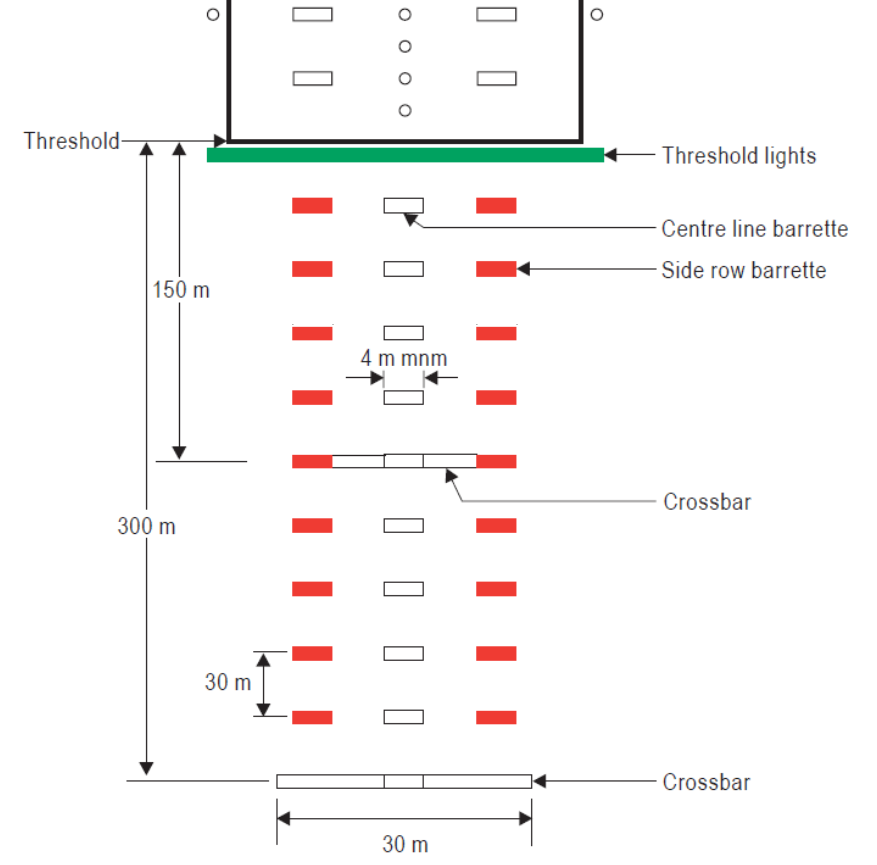
Keeping the system in specification
Most of what goes wrong with an ALS is invisible from the ground. A dark unit is easy to spot on a night walk, but a red filter that has faded, a barrette that has drifted a degree off aim, or a flasher that fires late shows only in the picture the crew sees from the approach. That is why ADR.OPS.C.015 and Annex 14 state the serviceability limits by section rather than by unit, and why photometric checks are flown rather than walked.
TarmacView’s approach lights inspection flies the approach at the heights a crew sees it from and reports pattern, colour, intensity build-up, coverage, dimming steps and the flashing sequence against the tolerances above, in the protocol format your authority expects.
Related terms
ALS, ALSF and MALSR are separate glossary entries with the configuration drawings for each. Sequenced flashing lights and threshold lights have their own entries, and the runway lighting entry covers what begins where the approach system ends.
Frequently Asked Questions
- What does an approach lighting system do for approach minimums?
- A serviceable ALS lets a runway carry lower visibility minimums, because the pilot can pick up the lights before the runway itself. If part of the system is out, the published minimums rise by the amount given in the state's inoperative-components table, and under 14 CFR 91.175 a pilot may continue below decision height on the approach lights alone only down to 100 ft above the touchdown zone.
- What is the difference between ALSF-2 and MALSR?
- Both are 2,400 ft (732 m) long. ALSF-2 is a high-intensity system with centreline light bars every 100 ft, red side row bars over the inner 900 ft and 15 sequenced flashers, and it supports CAT II and III. MALSR is a medium-intensity CAT I system with bars every 200 ft, 1,400 ft of steady lights and 1,000 ft of runway alignment indicator lights (RAIL) beyond them.
- How long is an approach lighting system?
- CS-ADR-DSN and ICAO ask for 900 m from the threshold on a precision approach runway wherever the site allows, and at least 420 m for a simple approach lighting system. The full FAA systems (ALSF-2, SSALR, MALSR) are 2,400 ft (732 m), the shorter MALS and MALSF are 1,400 ft (427 m).
- Why are some approach lights red?
- Red side row barrettes either side of the centreline in the inner 270 m (ICAO) or 900 ft (FAA ALSF-2) mark the CAT II and III inner section, so the crew can judge roll and lateral position in the last seconds before the threshold. The legacy FAA ALSF-1 shows red bars near the threshold instead. Centreline and crossbar lights are white.
- Can pilots switch on approach lights themselves?
- At many uncontrolled fields in the United States the ALS is on pilot-controlled lighting: keying the microphone on the published frequency turns the system on for a set period, and the number of clicks selects the intensity step. At towered airports the controller sets the intensity.
References
- icao-annex14-vol1
- Annex 14 to the Convention on International Civil Aviation, Volume I: Aerodrome Design and Operations, 9th edition ICAO
- faa-ac-150-5340-30
- AC 150/5340-30J, Design and Installation Details for Airport Visual Aids FAA
- easa-ear-aerodromes
- Easy Access Rules for Aerodromes (Regulation (EU) No 139/2014), including CS-ADR-DSN Issue 7 EASA
- uk-caa-cap-168
- CAP 168, Licensing of Aerodromes, Edition 13 UK Civil Aviation Authority
- nato-stanag-3316
- STANAG 3316, Airfield Lighting NATO Standardization Office
- faa-jo-6850-2
- Order JO 6850.2C, Visual Guidance Lighting Systems FAA
This is a reference entry. TarmacView provides drone inspection services and doesn't sell the equipment or materials described in this glossary.