What is an approach slope in aviation?
Approach Slope and Related Concepts in Aviation
1. Introduction
A safe and stabilized approach is the cornerstone of every landing in aviation. The approach slope, the angle at which an aircraft descends towards the runway, is fundamental to achieving this. Understanding the approach slope, its measurement, associated aerodynamic angles, and the visual and electronic aids that help pilots maintain it, is essential for all aviators. This glossary entry offers a comprehensive look at the approach slope and its related concepts, providing pilots, students, and enthusiasts with the foundational knowledge needed for safe and proficient approach and landing operations.
2. Approach Slope (Angle of Descent Path Relative to Horizontal)
Definition:
The approach slope is the angle formed between an aircraft’s intended descent path on final approach and the horizontal plane of the earth. It is typically expressed in degrees and represents the optimum path for a safe, stabilized landing.
Where is it Used?
- Instrument Approaches: Published glide paths on approach charts (ILS, LPV, LNAV/VNAV).
- Visual Approaches: Visual references, often augmented by approach slope indicator systems at the airport.
Typical Values and Standards
- Standard Value: 3° (approx. 5.24% gradient), recommended by ICAO and FAA for most runways.
- Range: Can vary from 2.5° (shallow) to 4.5° (steep), depending on terrain, obstacles, or special procedures.
Reference:
Calculation Example
A 3° approach slope will result in a descent of approximately 318 feet per nautical mile (NM):
Descent per NM = 6076 ft (1 NM) × tan(3°) ≈ 318 ft
Importance
Correctly flying the approach slope ensures:
- Obstacle and terrain clearance
- Stabilized approach, improving landing success and safety
- Consistent touchdown point on the runway
3. Glide Path / Glide Slope
Definition:
The glide path (or glide slope) is the actual or electronically defined descent trajectory the aircraft follows to the runway, ideally matching the published approach slope.
Types
- Visual Glide Path: Defined by visual aids (VASI, PAPI).
- Electronic Glide Path: Defined by ILS, MLS, or GPS/WAAS systems.
Operational Use
- Visual Approaches: Pilots align visually with slope indicators.
- Instrument Approaches: ILS glide slope guidance on cockpit displays.
Standards
- ILS Glide Slope: Provides precise vertical guidance, typically set at 3°.
- PAPI/VASI: Visual systems set to match the published approach slope.
Reference:
4. Pitch Angle
Definition:
Pitch angle is the angle between the aircraft’s longitudinal axis (nose-to-tail) and the natural horizon, as displayed on the attitude indicator.
Key Points
- Pitch ≠ Approach Slope: The nose may be level or even slightly up on a 3° approach, depending on configuration and speed.
- Role: Used for attitude and airspeed control, not direct slope reference.
Example
A heavy jet may fly a 3° approach with a pitch angle of +1° to 0°, while a light aircraft may show a negative pitch.
Reference:
5. Angle of Attack (AoA)
Definition:
Angle of Attack is the angle between the wing chord line and the direction of the oncoming airflow (relative wind). It determines lift and stall characteristics.
Significance
- Lift Generation: Moderate AoA increases lift, excessive AoA causes stall.
- Stabilized Approach: Correct AoA ensures adequate stall margin.
AoA vs. Approach Slope
AoA is independent of approach slope. A pilot can be on the correct approach slope but at a dangerously high AoA (and thus risk stalling), especially at low speeds.
Reference:
6. Flight Path Angle (FPA)
Definition:
Flight Path Angle describes the angle between the aircraft’s trajectory and the horizontal. Negative FPA during approach equals the descent angle.
Relationship
- FPA ≈ Approach Slope: On a standard approach, a -3° FPA matches a 3° approach slope.
- FPA ≠ Pitch Angle: Pitch angle is the aircraft’s nose attitude, not the path flown.
Calculation
FPA (deg) = arctan (vertical speed / (60 × groundspeed in NM/min))
Reference:
7. Comparison Table: Approach-Related Angles
| Term | Definition | Reference | Typical Value | Operational Use |
|---|---|---|---|---|
| Approach Slope | Descent path angle vs. horizontal | Path vs. ground | 3° | Published per runway |
| Glide Path | Actual trajectory to runway | Path vs. ground | Matches slope | Visual/electronic guidance |
| Pitch Angle | Aircraft axis vs. horizon | Attitude indicator | Varies | Attitude/airspeed control |
| Angle of Attack | Wing chord vs. airflow | AoA indicator | Varies | Stall/lift management |
| Flight Path Angle | Trajectory angle vs. horizontal | Path marker | -3° (standard) | Descent/performance planning |
8. Visual and Electronic Approach Slope Indicator Systems
Modern airports employ a variety of aids to help pilots fly the correct approach slope.
8.1 Visual Approach Slope Indicator (VASI)
Definition:
System of red and white lights (bars) beside the runway indicating position above/below the standard approach slope.
- Red over White: On the glide path
- Red over Red: Below (too low)
- White over White: Above (too high)
Mnemonic:
“Red over white, you’re alright. Red over red, you’re dead.”
Reference:
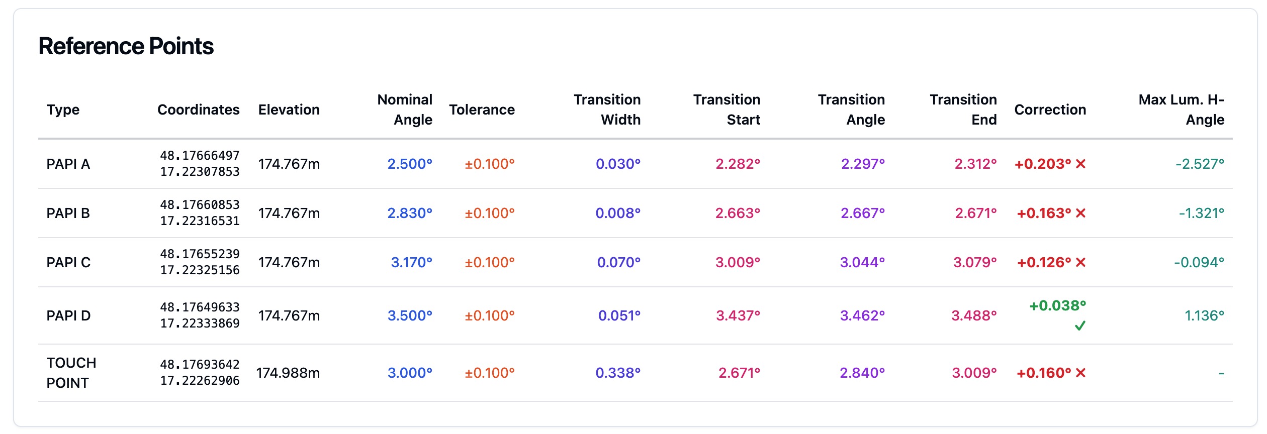
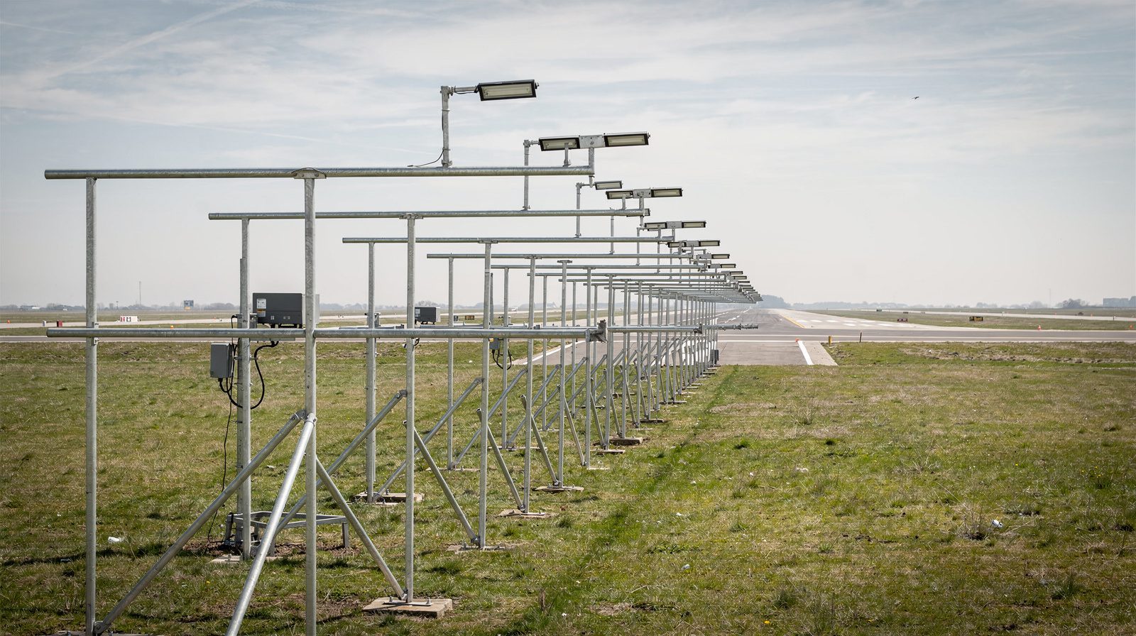
8.2 Precision Approach Path Indicator (PAPI)
Definition:
Four-light system giving finer resolution of position relative to the approach slope.
- 2 Red, 2 White: On slope
- More Red: Too low
- More White: Too high
Mnemonic:
“Four reds, you’re dead. Two and two, you’re cool.”
Reference:
8.3 Tri-Color Visual Approach Slope Indicator
Definition:
Single-unit light displays green (on slope), red (below), or amber (above) depending on approach angle.
Reference:
8.4 Pulsating Visual Approach Slope Indicator (PVASI)
Definition:
Single light emits steady white (on slope), pulsating white (too high), or steady/pulsating red (too low).
9. Practical Calculations and Rules of Thumb
9.1 Top of Descent (TOD)
To calculate where to start descent for a 3° approach:
TOD (NM) = (Altitude to lose in feet) / 300
Example: Descend from 9000 ft to airport at 1000 ft (lose 8000 ft):
8000 / 300 ≈ 27 NM from the airport.
9.2 Rate of Descent (ROD)
ROD (ft/min) ≈ Groundspeed (kt) × 5
For a 120 kt approach: 120 × 5 = 600 ft/min (for 3° slope).
9.3 Wind Correction
Headwinds reduce the required rate of descent, tailwinds increase it. Adjust the ROD accordingly.
10. Mnemonics and Memory Aids
- VASI: “Red over white, you’re alright. Red over red, you’re dead.”
- PAPI: “Four reds, you’re dead. Two and two, you’re cool. Four whites, you’re high as a kite.”
11. Regulatory and Operational Considerations
11.1 Regulations
- ICAO Annex 14: Sets standards for runway approach slopes, lighting systems.
- FAA AIM and Orders: Define approach slope, obstacle clearance, and approach lighting.
Reference:
11.2 Approach Planning and Safety
- Always review published approach plates for slope, lighting, and obstacles.
- Maintain stabilized approach criteria as set by operator or authority.
12. Operational Examples
- Short Field: Steeper slope (e.g., 4°) may be published for obstacle clearance.
- Urban Airports: London City (EGLC) uses a 5.5° approach due to surrounding buildings.
- Mountain Airports: May have special approach slopes and unique visual aids.
13. Best Practices
- Always verify and brief the published approach slope.
- Use visual/electronic aids as primary reference.
- Cross-check with vertical speed and groundspeed.
- Understand and monitor AoA, especially in slow flight.
- When in doubt, go around and re-establish a stabilized approach.
14. References and Further Study
- Annex 14 to the Convention on International Civil Aviation
- FAA Aeronautical Information Manual
- Instrument Landing System (ILS) – Wikipedia
- Angle of Attack – Wikipedia
- Precision Approach Path Indicator – Wikipedia
- Aircraft Principal Axes – Wikipedia
- FAA Airplane Flying Handbook
- Visual Approach Slope Indicator – Wikipedia
Summary:
The approach slope is a foundational concept in aviation approach and landing, underpinned by aerodynamic principles and enforced by regulatory standards. Understanding its distinction from pitch angle, angle of attack, and flight path angle is vital for every pilot. Visual and electronic aids, proper calculation, and adherence to best practices ensure safety and consistency in every landing.
Frequently Asked Questions
- What is a standard approach slope in aviation?
- A standard approach slope is typically set at 3°, providing a safe compromise between obstacle clearance and operational efficiency. This value is recommended by ICAO and widely adopted for both instrument and visual approaches. Some runways may have approach slopes as shallow as 2.5° or as steep as 4.5° based on local terrain or obstacles.
- How do pilots maintain the correct approach slope?
- Pilots maintain the correct approach slope using visual aids (like PAPI or VASI lighting systems) or electronic guidance (such as the ILS glide slope or GPS-based vertical guidance). Cockpit instruments, including the vertical speed indicator and primary flight display, help monitor and maintain the desired descent angle.
- What is the difference between approach slope and pitch angle?
- Approach slope (or flight path angle) measures the angle of the aircraft's descent path relative to the ground. Pitch angle measures the aircraft's nose-up or nose-down orientation relative to the horizon. They are not the same: during a standard 3° approach, the pitch angle may be level or even slightly nose-up, depending on aircraft type and configuration.
- Why is approach slope important for safe landings?
- Maintaining the proper approach slope ensures obstacle clearance, a stabilized approach, and touchdown at the correct runway point. Deviating from the intended slope increases risks such as undershoot, overshoot, or unstabilized approaches, which can compromise safety.
- What visual aids help pilots fly the correct approach slope?
- Visual aids like the Precision Approach Path Indicator (PAPI) and Visual Approach Slope Indicator (VASI) provide clear, color-coded light signals to help pilots judge and correct their approach angle. These systems are standardized and installed at most controlled airports.
- How does wind affect the approach slope?
- Headwinds decrease the required rate of descent for a given approach slope, while tailwinds increase it. Pilots must adjust their vertical speed to maintain the correct approach angle, especially in gusty or shifting wind conditions.
- What is the angle of attack, and how does it relate to approach slope?
- Angle of attack (AoA) is the angle between the wing chord and the oncoming airflow. It determines lift and the risk of stall. AoA is independent of approach slope: a pilot can maintain the correct approach slope at a dangerously high AoA if airspeed gets too low, risking a stall.
- What are the regulatory standards for approach slopes?
- International standards, such as ICAO Annex 14 and FAA Orders, specify approach slope parameters, obstacle clearance requirements, and lighting system design. These regulations ensure consistency and safety across airports worldwide.
- What are the consequences of flying below or above the approach slope?
- Flying below the approach slope increases the risk of colliding with obstacles or terrain, flying above it may result in a landing that is too far down the runway or an unstable approach. Both deviations can lead to go-arounds or unsafe landings.
- What is the difference between PAPI and VASI?
- PAPI consists of a row of four lights that provide precise, continuous glide path information, while VASI typically uses two or three bars of lights to provide stepwise guidance. Both indicate whether the aircraft is above, on, or below the approach slope, but PAPI offers finer resolution.
This is a reference entry. TarmacView provides drone inspection services and doesn't sell the equipment or materials described in this glossary.