What is the approach zone?
Approach Zone
Definition and Regulatory Framework
The approach zone is a precisely defined segment of airspace and ground preceding the runway threshold, purpose-built and regulated to enable safe, stabilized aircraft descent and alignment with the runway for landing. It is foundational to both visual and instrument approach procedures, with design and operational criteria established by global and national aviation authorities such as the International Civil Aviation Organization (ICAO) and the Federal Aviation Administration (FAA) .
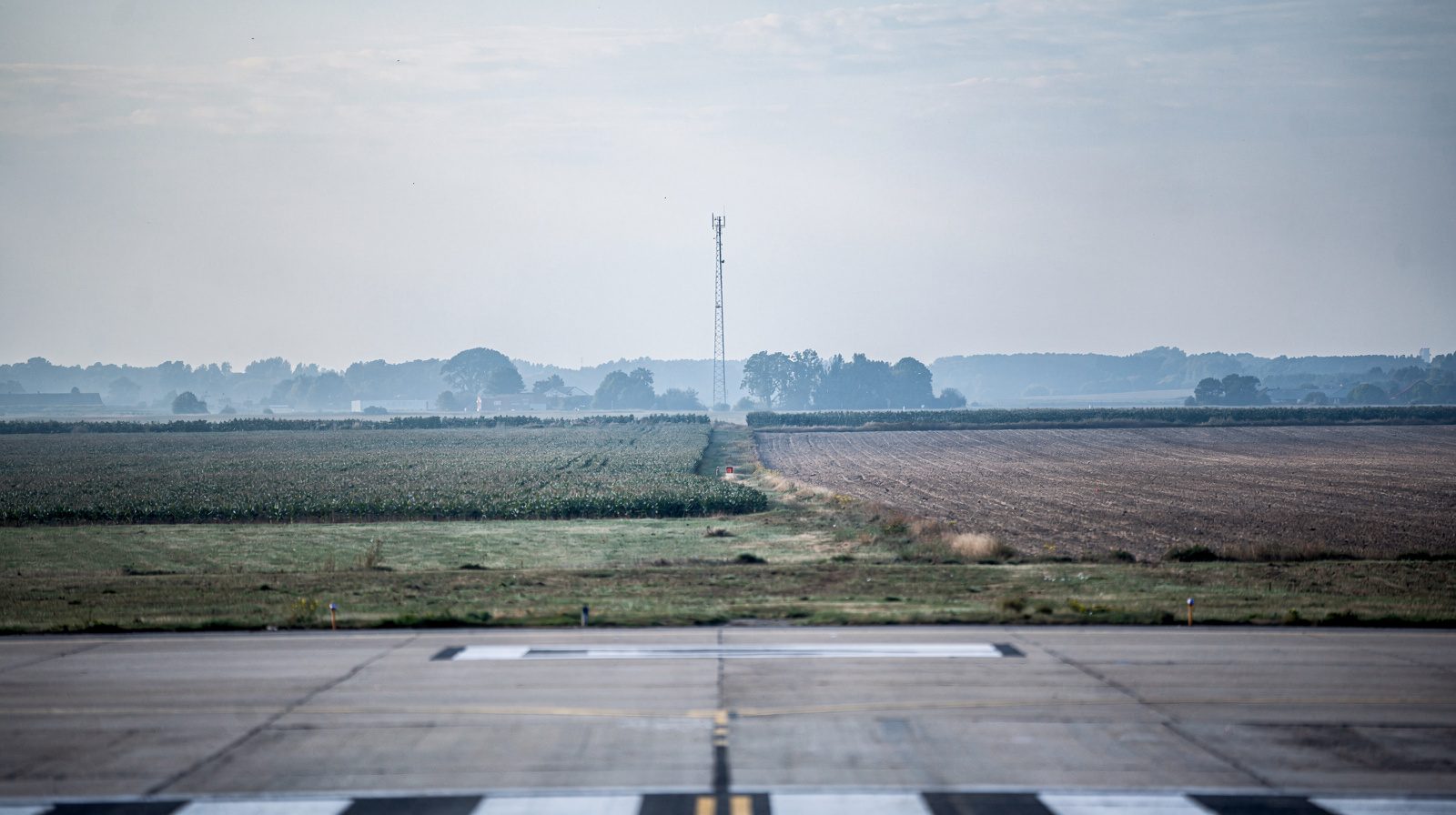
The approach zone includes both an approach surface, an imaginary sloped plane extending outward and upward from the runway threshold, and the associated airspace segment through which aircraft must fly during final approach. Its geometry, obstacle clearance requirements, and integration with navigational and visual aids are detailed in ICAO Annex 14 and FAA Title 14 CFR Part 77 .
Key Points:
- Located immediately before the runway threshold, from the final approach fix (FAF) or final approach point (FAP) to the runway threshold.
- Provides a safe, obstacle-free, and regulated descent corridor.
- Supports both instrument and visual approaches, integrating electronic and visual landing aids.
Spatial and Geometric Characteristics
Engineering the Approach Surface
The approach surface is a three-dimensional sloped area extending outward and upward from an inner edge located 60 meters before the runway threshold, designed to guarantee obstacle clearance and safe descent. The figures below describe its first section, which is followed by a second section at a steeper gradient.
| Runway Type | Inner Width | Outer Width | First Section Length | First Section Slope |
|---|---|---|---|---|
| Precision CAT I | 300 m | 1200 m | 3000 m | 2.0% (1.15°) |
| Precision CAT II/III | 300 m | 1200 m | 3000 m | 2.0% (1.15°) |
| Non-Precision | 150 m | 600 m | 2500 m | 2.5% (1.43°) |
References: ICAO Annex 14 Vol. I , FAA CFR Part 77
Location and Boundaries
- Initiation Point: At the inner edge, 60 meters before the runway threshold.
- Termination: Extends outward for a prescribed distance, widening and rising to enable obstacle clearance.
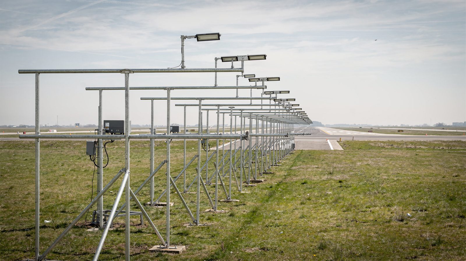
- Relation to Lighting: Covers the area above and around approach lighting systems (ALS).
Operational Implications
- Obstacle Limitation Surfaces (OLS): The approach surface is part of the OLS, protecting the final approach path from obstructions.
- Glide Path Provision: The approach surface aligns with standard glide slopes (typically 3°) for safe descent.
Relationship to Other Airport Operational Areas
Runway Threshold, Final Approach, and Touchdown Zone
- Runway Threshold: The physical start of the runway for landings, marked with distinctive stripes.
- Final Approach Segment: The segment from the FAF/FAP to the runway threshold, where pilots transition into the landing configuration and maintain alignment.
- Touchdown Zone (TDZ): The first 3,000 feet or one-third of the runway past the threshold, marked for safe landing and deceleration.
- Aiming Point: Markings (broad white rectangles) typically 1,000 feet from the threshold, used as a visual glide path reference.
Schematic Representation
|---Approach Zone---|---Threshold---|---Aiming Point---|---Touchdown Zone---|
        |                 |                |                       |
   (FAF/FAP)        (Runway Start)   (1,000 ft)             (First 3,000 ft)
References: FAA AIM, 4-3-3
Purpose and Function
Controlled Descent and Safety
The approach zone is the transition area from approach phase to landing, ensuring a stabilized descent. Pilots use this zone to:
- Align with the runway using navigational aids and visual references.
- Descend along a standard glide path (typically 3°).
- Prepare for flare and touchdown, configuring gear, flaps, and speed.
Objectives:
- Obstacle Clearance: No structures penetrate the approach surface.
- Guidance: Supports both instrument (IMC) and visual (VMC) approaches.
- Standardization: Ensures repeatable, safe approaches regardless of aircraft type or weather.
References: ICAO Doc 8168 , FAA Airplane Flying Handbook, Ch. 9
Operational Procedures
Standard Approach Sequence
- Interception: Align with the extended runway centerline using ILS, VOR, RNAV, or visual cues.
- Configuration: Extend landing gear, select flaps, and adjust speed for landing.
- Descent Path: Maintain a constant descent rate on the glide path, using visual aids (PAPI, VASI) or ILS.
- Aiming Point: Hold the aiming point stationary in the windscreen for a stabilized approach.
- Flare and Touchdown: Initiate flare at ~50 feet above threshold, touchdown occurs within the touchdown zone.
Instrument Approach
- FAF/FAP: The point where final approach begins, ILS approaches intercept the glide slope here.
- Missed Approach Point (MAP): If required visual references are not obtained, initiate missed approach.
Visual Approach
- Pattern Entry: Enter traffic pattern, align visually, and use markings/PAPI/VASI for guidance.
References: FAA Instrument Procedures Handbook
Visual Cues and Markings
Runway Markings
- Threshold: Multiple white stripes across runway start.
- Aiming Point: Two broad rectangles, 1,000 feet from threshold.
- Touchdown Zone: Series of white bars every 500 feet up to 3,000 feet.
Approach Lighting Systems (ALS)
- Purpose: Visual extension of runway centerline, aiding transition from instrument to visual flight.
- Types: ALSF-1/2 (high intensity), MALSR (medium), SSALR/ODALS (simplified).
ALS Layout Example
[Runway Threshold]
|---Barrette Lights---|---Sequenced Flashers---|
(Extending up to 2,400 ft from threshold)
Visual Glide Path Indicators
- VASI: Red and white light bars beside runway.
- PAPI: Four-unit row, red/white combination for precise guidance.
Sight Picture
- The aiming point is stationary in the windshield for a stabilized approach.
- Runway edges converge peripherally as the aircraft descends.
References: ICAO Annex 14, Sections 5.3 & 5.4
Safety and Regulatory Considerations
Obstacle Clearance
- Obstacle-Free Zone (OFZ): The approach surface must remain free of penetrations by obstacles.
- Regulatory Standards: ICAO Annex 14 and FAA Part 77 set precise criteria.
Stabilized Approach
- Definition: Aircraft fully configured, on speed, and on path by 1,000 feet AGL (IMC) or 500 feet (VMC).
- Requirement: Go-around if not stabilized by these altitudes.
Touchdown Zone Compliance
- Requirement: Land within the first third or 3,000 feet of runway.
- Deviation: Touchdown outside this zone may be considered an incident.
Common Hazards
- Runway Incursion: Unauthorized presence in the approach zone.
- Wrong Surface Landing: Misidentification of the landing runway.
References: FAA Airplane Flying Handbook
Technical Glossary Table
| Term | Definition |
|---|---|
| Approach Zone | Airspace and flight path before runway threshold, for safe, controlled descent. |
| Final Approach | Last approach segment, aligned with runway centerline, descending to land. |
| Aiming Point | Marking used as glide path reference, 1,000 ft from threshold. |
| Touchdown Zone (TDZ) | First 3,000 ft or one-third of runway beyond threshold for landing. |
| Runway Threshold | Start of usable runway, marked by stripes. |
| Glide Slope | Standard descent angle (typically 3°) for final approach. |
| Final Approach Fix (FAF) | Start of final descent in instrument approaches. |
| Approach Lighting System | Lighting system extending into approach zone for visual runway acquisition. |
| Obstacle-Free Zone (OFZ) | Protected area in approach kept free of obstacles. |
Examples and Use Cases
Visual Approach Example
A pilot flying a general aviation aircraft enters the final approach, identifies the aiming point markings and PAPI lights, and maintains a 3° glide path. At 50 feet above the runway threshold, the flare is initiated and touchdown occurs in the TDZ.
Instrument Approach Example
A commercial aircraft performs a Category I ILS approach. At the FAF, the crew intercepts the localizer and glide slope. The approach lighting system helps with final alignment as the aircraft transitions from instrument to visual flight, crossing the threshold at the correct height for a safe landing.
Short Field Landing
On a short runway, the approach must be tightly controlled. The aircraft is fully configured early, descent is stabilized toward the aiming point, and a prompt flare ensures touchdown within the first third of the runway.
Practical Tips for Pilots
- Use the Aiming Point: Reference the aiming point for glide path, not as the touchdown point.
- Stabilize Early: Configure the aircraft and establish a stable path before entering the approach zone.
- Rely on Aids: Use PAPI, VASI, and ALS, especially in low visibility.
- Sight Picture: Keep the aiming point stationary in the windscreen.
- Adjust for Environment: Consider wind, slope, or wet surfaces for approach and stopping distance.
- Brief the Approach: Review all procedures and cues for the intended runway.
- Avoid Threshold Aiming: Obstacle clearance is calculated with the aiming point in mind.
- Go Around if Needed: If not stabilized or unable to touch down in the TDZ, execute a go-around.
Misconceptions and Error Prevention
| Misconception/Error | Correction/Explanation |
|---|---|
| Aiming for the runway threshold | Increases risk of undershoot, use aiming point for glide path. |
| Touching down on the aiming point | Flare moves touchdown beyond aiming point, this is correct. |
| Late stabilization of approach | May cause hard landings or overruns, stabilize by 1,000/500 ft AGL. |
| Retracting flaps to correct undershoot | Causes rapid sink/loss of lift, use power and pitch instead. |
| Ignoring approach lighting cues | Reduces situational awareness, especially in low visibility. |
Reference and Attribution
- ICAO Annex 14, Aerodromes
- FAA AIM, Section 4-3-3: Airport Operations
- FAA Airplane Flying Handbook, Chapter 9
- Jeppesen Chart User Guide
- FAA Instrument Procedures Handbook
- EASA Part-FCL Flight Training Manual
Summary Table: Approach Zone Key Points
| Aspect | Details |
|---|---|
| Definition | Airspace and flight path before the runway threshold for controlled descent and landing. |
| Boundaries | FAF/FAP to runway threshold, including airspace over approach lights and markings. |
| Markings and Visual Aids | Threshold, aiming point, touchdown zone, PAPI/VASI, approach lighting systems. |
| Standard Glide Path | 3°, unless otherwise dictated by approach or terrain. |
| Obstacle Clearance | Protected by approach surface and OFZ criteria. |
| Stabilized Approach | Required by 1,000 ft AGL (IMC) or 500 ft AGL (VMC), go-around if not achieved. |
Frequently Asked Questions
- How is the approach zone defined in terms of dimensions and slope?
- The approach zone’s dimensions and slope depend on runway category and approach type. Under ICAO Annex 14, the precision (CAT I) approach surface has its inner edge 60 meters before the runway threshold, is 300 meters wide there, and diverges 15% on each side. Its first section extends 3000 meters and rises at a 2% slope, reaching 1200 meters wide, and the second section then rises at 2.5%. These parameters are precisely set by ICAO Annex 14 and FAA Part 77.
- Why is obstacle clearance critical in the approach zone?
- Obstacle clearance ensures aircraft can descend safely without risk of collision with terrain or structures. Regulatory bodies define imaginary approach surfaces that must remain free of obstacles to enable safe operations, especially in low visibility or instrument meteorological conditions.
- What is the difference between the approach zone and the touchdown zone?
- The approach zone is the airspace and ground area preceding the runway threshold, guiding aircraft to the runway. The touchdown zone is the portion of the runway immediately after the threshold where the aircraft is expected to land, typically the first 3,000 feet or one-third of the runway.
- How do visual and electronic aids assist pilots in the approach zone?
- Visual aids such as approach lighting systems (ALS), PAPI, and VASI provide glide path and alignment cues. Electronic aids (ILS, RNAV, VOR) offer lateral and vertical guidance, especially under instrument meteorological conditions, ensuring a stabilized approach and smooth transition to landing.
- What should pilots do if the approach becomes unstabilized in the approach zone?
- If the approach is not stabilized by 1,000 feet above ground level in instrument conditions or 500 feet in visual conditions, pilots are required to execute a go-around, as continuing could lead to hard landings, runway overruns, or other incidents.
This is a reference entry. TarmacView provides drone inspection services and doesn't sell the equipment or materials described in this glossary.