An asphalt overlay is the placement of one or more new HMA layers over an existing pavement to restore structural capacity, improve ride quality, and/or enhance surface characteristics. Overlays are the most common pavement rehabilitation method. Covers overlay design (thickness; mix type; interlayer), pre-overlay repairs (patching; crack sealing; milling), reflective cracking mitigation, and post-overlay inspection.
What is an Asphalt Overlay?
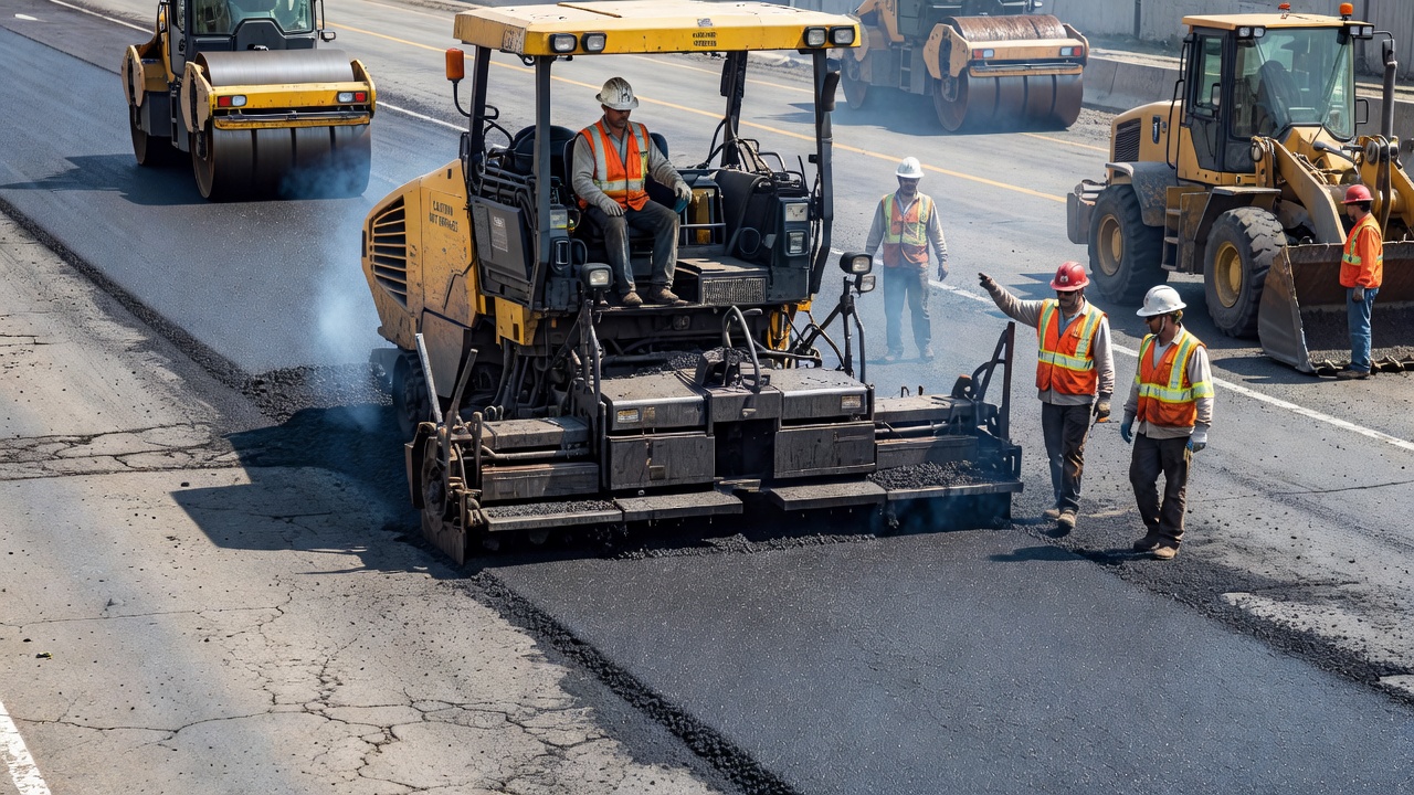
An asphalt overlay — also called an HMA overlay, bituminous overlay, or asphalt resurfacing — is the construction of one or more new hot mix asphalt (HMA) layers placed directly on an existing pavement surface. Overlays are the most widely used pavement rehabilitation method in the world, employed on interstate highways, airport runways, taxiways and aprons, municipal arterial and collector roads, parking lots, and industrial facility pavements.
The fundamental purpose of an asphalt overlay is to extend the service life of an existing pavement by restoring its structural capacity, improving its surface characteristics, or both. Overlays are distinct from reconstruction, which requires complete removal and replacement of the pavement structure down to the subgrade. Overlays are also distinct from surface treatments (chip seals, slurry seals, microsurfacing) which provide only thin surface renewal without significant structural contribution.
An asphalt overlay can consist of a single lift (one layer of HMA, typically 25 mm to 75 mm thick) or multiple lifts (two or more layers, total thickness typically 75 mm to 200 mm or more). Multiple-lift overlays allow the use of different mixture types for different functions — a leveling course (first lift) to fill irregularities and restore cross-slope, a structural intermediate course to provide load-carrying capacity, and a wearing course (surface lift) to provide ride quality, friction, and impermeability.
Per the Federal Highway Administration (FHWA) , overlays constitute the majority of all paving work performed in the United States — more than 50% of total HMA tonnage is used in overlay applications. The same proportion holds in Europe, Asia, and Australia, making overlay design and construction the most important skill set for pavement engineers and construction inspectors.
Structural vs Functional Overlay
The distinction between structural overlays and functional overlays (also called non-structural overlays or preservation overlays) is fundamental to pavement rehabilitation decision-making. The wrong choice leads to premature failure — applying a thin functional overlay on a structurally deficient pavement results in rapid fatigue cracking, while applying a thick structural overlay on a structurally sound pavement with surface distress only is economically wasteful.
Structural overlays are designed to increase the load-carrying capacity of an existing pavement to accommodate either heavier traffic loads or a longer design period (typically 15 to 20 years). Structural overlays are required when the existing pavement has lost significant structural capacity due to fatigue damage, subgrade weakening, or accumulated load repetitions approaching the pavement’s design life. The design of structural overlays uses engineering methods that quantify the structural deficiency of the existing pavement and determine the additional thickness required. The primary design methodologies are the AASHTO 1993 structural number (SN) deficit method (for highway pavements) and the FAARFIELD layered elastic analysis method (for airport pavements per FAA AC 150/5320-6G). Structural overlays typically range from 75 mm (3 inches) to 150 mm (6 inches) or more in total thickness and may require multiple lifts of different mixture types.
Functional overlays (also called thin asphalt overlays or preservation overlays) are designed to restore surface characteristics without adding significant structural capacity. According to FHWA Technical Brief HIF-19-053, a thin asphalt overlay is defined as a dense-graded HMA mixture with nominal maximum aggregate size (NMAS) of 4.75 mm or 9.5 mm, placed at a thickness of less than 38 mm (1.5 inches) using conventional asphalt production and placement operations. Functional overlays are applied when the existing pavement is structurally sound but exhibits surface deficiencies such as reduced friction, minor rutting (less than 6 mm), surface raveling, oxidation, water infiltration, or unacceptable ride quality. Key benefits of functional overlays include: improved ride smoothness, correction of minor rutting, reduced water infiltration (impermeability when compacted to less than 10% air voids), restarted surface aging, and decreased tire-pavement noise. Functional overlays are classified as pavement preservation treatments and are intended to extend service life by 7 to 12 years when applied at the optimal time — when the existing pavement is in good to fair condition but approaching the threshold of moderate distress.
Overlay Thickness Design
Overlay thickness design is the engineering process of determining the minimum thickness of new HMA required to meet the structural and performance requirements of the pavement for a specified design period. The design methodology differs fundamentally between highway pavements (AASHTO, mechanistic-empirical) and airport pavements (FAA FAARFIELD, ICAO).
AASHTO 1993 Structural Number Method
The AASHTO 1993 Guide for Design of Pavement Structures provides the most widely used overlay design method for highway pavements. The method is based on the concept of structural number (SN) — an abstract index number representing the overall structural capacity of a pavement section, calculated as the sum of each layer’s thickness multiplied by its structural layer coefficient:
SN = a₁D₁ + a₂D₂m₂ + a₃D₃m₃
Where a₁, a₂, a₃ are layer coefficients (0.40 to 0.44 for dense-graded HMA), D₁, D₂, D₃ are layer thicknesses in inches, and m₂, m₃ are drainage coefficients (0.70 to 1.40 depending on drainage quality).
The overlay design procedure involves five steps:
Step 1 — Determine the required structural number (SN_req) for the future traffic loading over the design period. This requires inputs including: projected traffic (18-kip equivalent single axle loads, ESALs), terminal serviceability (p_t = 2.0 to 2.5 typical), reliability level (R = 50% to 99% depending on road class), standard deviation (S₀ = 0.40 to 0.50 for flexible pavements), subgrade resilient modulus (M_R from FWD or laboratory testing), and effective structural number of the existing pavement.
Step 2 — Determine the effective structural number (SN_eff) of the existing pavement. This is the most critical and complex step. SN_eff is determined through: (1) Visual condition survey — deduct values from the Pavement Condition Index (PCI) or Distress Index (DI) are used to estimate remaining structural life; (2) Nondestructive deflection testing — FWD deflection basins are analyzed to back-calculate layer moduli and SN_eff using programs like MODULUS, EVERCALC, or ELMOD; (3) Coring and laboratory testing — pavement cores are measured for layer thickness, and materials are tested for resilient modulus and binder properties. The remaining life factor (RLF) is applied to account for the damage already sustained by the existing pavement.
Step 3 — Calculate the overlay structural number (SN_ol) as: SN_ol = SN_req — SN_eff. If SN_eff is greater than SN_req, no structural overlay is needed.
Step 4 — Determine the overlay thickness (D_ol) by dividing the overlay structural number by the structural layer coefficient: D_ol = SN_ol / a_ol. The overlay layer coefficient (a_ol) is typically 0.40 to 0.44 for dense-graded HMA at standard densities, but can be as low as 0.30 for open-graded mixtures or as high as 0.50 for high-modulus mixtures with polymer-modified binders.
Step 5 — Apply minimum thickness constraints and lift thickness requirements. Minimum overlay thickness is typically 50 mm (2 inches) for structural overlays to ensure adequate compaction and structural contribution. Individual lift thickness should be at least three times the nominal maximum aggregate size (NMAS) of the mixture — for a 12.5 mm NMAS mixture, minimum lift thickness is 38 mm (1.5 inches).
FAA FAARFIELD Method for Airport Pavements
The FAA FAARFIELD (Federal Aviation Administration Rigid and Flexible Iterative Elastic Layer Design) software uses layered elastic analysis for airport pavement overlay design. FAARFIELD implements the design procedures from AC 150/5320-6G. Key differences from the AASHTO SN method include:
Traffic characterization — FAARFIELD uses the pass-to-coverage ratio concept, converting aircraft traffic passes into equivalent coverages based on aircraft gear geometry and wander. The design aircraft is selected based on the critical aircraft concept — the aircraft with the highest pavement loading demand, considering gross weight, tire pressure, gear configuration, and annual departures.
Minimum overlay thickness — FAA requires a minimum of 75 mm (3 inches) of HMA overlay for structural overlays on existing flexible pavements when designing for aircraft gross weights above 30,000 lbs. For lighter aircraft, minimum thickness is 50 mm (2 inches).
Mechanistic-Empirical Overlay Design
The AASHTOWare Pavement ME Design software provides mechanistic-empirical (M-E) overlay design that directly calculates pavement responses (stress, strain, deflection) under traffic loading and accumulates damage over the design period. M-E overlay design accounts for traffic load spectra (not just ESALs), climate effects (temperature, moisture through LTPP climate data), and material-specific distress transfer functions for fatigue cracking, thermal cracking, and rutting.
Pre-Overlay Repairs
Pre-overlay repairs are the single most important factor determining overlay success. As stated in the AASHTO Guide and reinforced by TRB research, defects in the existing pavement will reflect through even the best-constructed overlay within months to a few years if not properly addressed. Pre-overlay repairs include: full-depth patching, crack sealing, milling (cold planing) , leveling course placement, and surface cleaning.
Full-Depth Patching
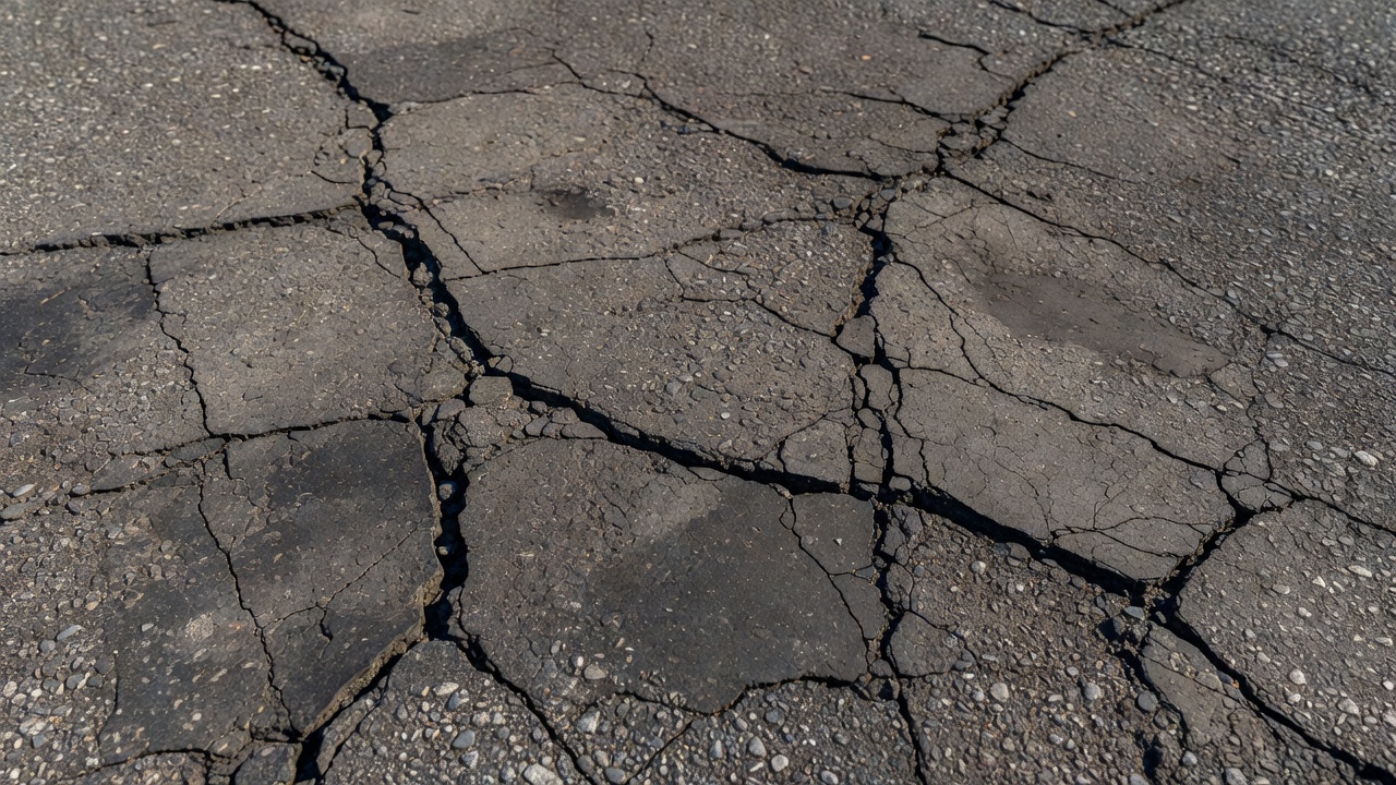
Full-depth patching involves removing the existing HMA and base layers down to the subgrade in localized areas of structural failure and replacing them with new HMA or, in some cases, with a stabilized base and HMA surface. This repair is required for areas exhibiting: fatigue (alligator) cracking — interconnected cracks forming a pattern resembling alligator hide, indicating structural failure of the pavement under repeated traffic loading; potholes — localized depressions that have broken through the full HMA thickness; base or subgrade failures — areas with pumping (erosion of fine material through cracks) or observable base failure; and severe rutting — rut depths exceeding 15 mm (0.6 inches) indicating instability in the HMA or base.
The full-depth patch should extend at least 300 mm (12 inches) beyond the visible distressed area into sound pavement on all sides. The patch sides are saw-cut vertically to provide a clean joint, the existing pavement is removed in full depth, the base and subgrade are inspected and repaired if necessary, and the new HMA is placed in lifts and compacted to match the existing pavement density. Tack coat is applied to all vertical faces of the patch before backfilling.
Crack Sealing
Crack sealing before overlay is a critical but often overlooked step. According to the TxDOT Pavement Manual (Section 3.5.1) and Pavement Interactive, existing cracks should be cleaned with pressurized air (or routed for cracks less than 10 mm wide) and filled with hot-applied crack sealant. The sealant prevents intrusion of water into the pavement structure during construction and delays reflective cracking by filling the crack void.
Crack sealing requirements by crack type and width are: Narrow cracks (less than 3 mm) — too narrow for sealant entry, must be routed (widened using a mechanical router to 12-19 mm wide, 12-19 mm deep) before sealing. Medium cracks (3-10 mm) — cleaned with hot compressed air and filled with sealant. Wide cracks (10-25 mm) — cleaned and filled with sealant; if excessive, full-depth patching may be more economical. Fatigue-cracked areas — not suitable for crack sealing; these areas require full-depth patching.
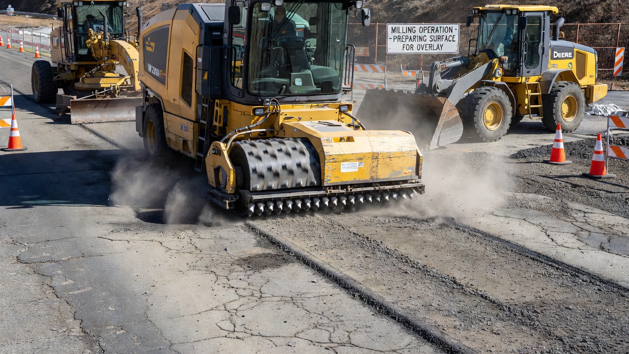
Milling (Cold Planing)
Milling (also called cold planing or cold milling) is the mechanical removal of the existing pavement surface using a rotating cutting drum equipped with tungsten carbide cutting teeth. Milling is used to: remove rutting, bumps, and deteriorated surface material; restore longitudinal and transverse grade and cross-slope; remove a layer of distressed HMA that would reflect through the new overlay; provide a clean, roughened surface for bonding; and maintain existing clearances beneath overhead structures.
Milling machine parameters per the Asphalt Recycling and Reclaiming Association (ARRA) include: cut width from 75 mm (3 inches) to 4.5 m (14 feet), cut depth up to 250 mm (10 inches) per pass, production rate of 100-200 tons per hour for large machines, and material size after milling typically 95% passing the 50 mm sieve. The milled surface is a grooved texture that increases surface area by 20-30% compared to an unmilled surface, requiring a corresponding increase in tack coat rate.
Leveling Course
A leveling course (or level-up course) is a variable-thickness HMA lift placed on the existing pavement before the final overlay to fill low spots, depressions, ruts, and irregularities. Leveling courses are placed using a paver with automatic screed control that references a fixed point to maintain constant screed elevation regardless of the tractor unit’s vertical movement over the uneven surface. The leveling course thickness is as thick as the deepest low spot but generally not less than 25 mm (1 inch) or more than 75 mm (3 inches) in a single pass.
Interlayer Bonding (Tack Coat)
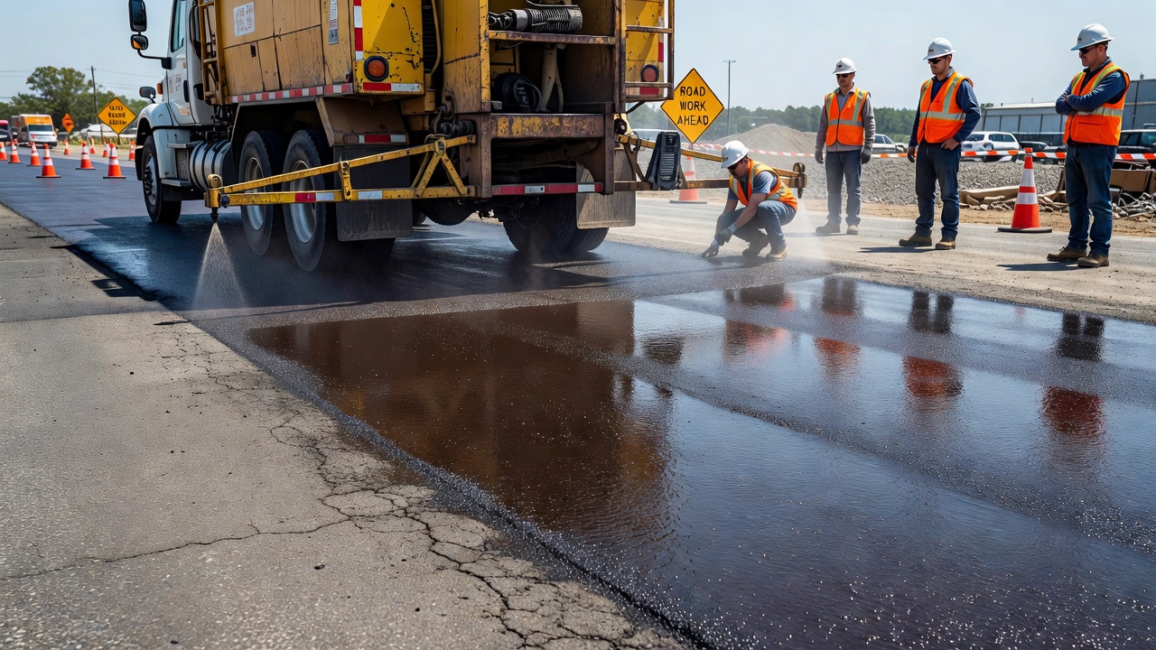
Tack coat is a thin layer of asphalt emulsion (or, less commonly, hot-applied PG binder) sprayed between the existing pavement surface and the new overlay to ensure full bonding between layers. Tack coat is essential because an unbonded overlay behaves as a thin independent layer subjected to bending stresses and shear forces it was not designed to resist, leading to premature failure through delamination, slippage cracking, and accelerated fatigue cracking.
Tack Coat Types
Tack coat materials are primarily asphalt emulsions. Common types include: SS-1h (slow-setting, hard grade) — the most common tack for overlays on existing HMA; CSS-1h (cationic slow-setting, hard grade) — for better adhesion to certain aggregates; RS-2, CRS-2 (rapid-setting emulsions) — for faster curing when traffic must be accommodated; Trackless emulsions — polymer-modified, quick-setting emulsions that dry rapidly but are reactivated by heat from the new HMA; and PG binder — hot-applied binder for maximum bond strength.
Tack Coat Application Rates
Application rate is the most critical tack coat parameter. Milled surfaces require 20-30% more tack coat due to increased surface area. Too little tack coat results in inadequate bonding; too much creates a lubricated slippage plane between layers or can cause bleeding in thin overlays.
Stress-Absorbing Membrane Interlayer (SAMI)
A Stress Absorbing Membrane Interlayer (SAMI) is a specialized interlayer system consisting of a heavy application of asphalt rubber binder (or polymer-modified binder) at rates of 1.5 to 2.5 kg/m², covered with aggregate chips. The SAMI absorbs horizontal movements from the cracked pavement below, preventing these cracks from propagating through the new overlay.
Reflective Cracking Mitigation
Reflective cracking is the propagation of pre-existing cracks, joints, or discontinuities from the underlying pavement layer through the new HMA overlay. It is the most common cause of overlay failure and the single greatest technical challenge in overlay engineering. Reflective cracks typically appear within 1 to 3 years after overlay placement.
Reflective cracking occurs through two primary mechanisms. Horizontal (thermal) movement — when the underlying pavement contracts due to temperature drop, the crack or joint opens, generating tensile stresses that propagate upward through the overlay. Vertical (traffic) movement — when a wheel load passes over a crack or joint, the pavement on the loaded side deflects more than the unloaded side, creating differential vertical movement (shear stress) that propagates through the overlay.
Mitigation Strategies
The Texas Transportation Institute (TTI Report 1777-P2) categorizes reflective cracking mitigation strategies into three groups:
Group 1 — Reinforcement of the overlay: (a) Thicker overlay — increasing overlay thickness reduces stress at the crack tip. (b) Fiber-reinforced HMA — adding polyester or polypropylene fibers (typically 0.3% to 0.5% by mass). (c) Polymer-modified binders — SBS or SBR-modified binders increase elastic recovery and tensile elongation capacity. (d) High-modulus grids — fiberglass or polymeric grids placed at the bottom of the overlay provide high tensile stiffness at low strain levels.
Group 2 — Stress-relieving interlayers: (a) Stress Absorbing Membrane Interlayer (SAMI) — a heavy asphalt rubber seal coat. (b) Open-graded HMA interlayer — a permeable HMA layer with high binder content. (c) Geotextile fabric interlayer — a nonwoven polypropylene or polyester fabric (typically 4-6 ounces/yd²) placed on a tack coat and saturated with asphalt, acting as both a stress-relieving layer and a moisture barrier.
Group 3 — Restrengthening of the cracked pavement before overlaying: (a) Crack and seat — for PCC pavements, the concrete slabs are cracked into pieces using a drop hammer, then seated by rolling. (b) Rubblization — the PCC pavement is broken into small pieces that act as an aggregate base, eliminating all slab action and reflective cracking potential. (c) Heater scarification — heating the existing HMA surface and scarifying the heated material, blending it with new HMA to create a homogeneous layer.
Airport Pavement Overlay Specifications
FAA Specifications (AC 150/5370-10H)
FAA Advisory Circular 150/5370-10H — Standard Specifications for Construction of Airports defines the materials and construction requirements for airport asphalt overlays through Item P-401 (Plant Mix Bituminous Pavements) .
Mixture Gradations and Lift Thickness: The FAA defines three gradation designations. Gradation 1 (25 mm NMAS, minimum lift 75 mm) — used for structural overlays. Gradation 2 (19 mm NMAS, minimum lift 50 mm) — the most common overlay gradation. Gradation 3 (12.5 mm NMAS, minimum lift 38 mm) — used for surface course overlays and functional overlays.
Binder Grade Selection: FAA requires PG binders per ASTM D6373 at 98% reliability for commercial service airports. Grade bumping: bump high-temperature grade by one grade (6°C) for tire pressures 150-200 psi, two grades for tire pressures above 200 psi.
Density Requirements: Target density is 96.0% of G_mm (Rice density per ASTM D2041), with no individual test below 94.0%.
Surface Tolerance: Maximum deviation of 6 mm (1/4 inch) from a 4.9 m (16 ft) straightedge.
ICAO Standards
ICAO Annex 14 and the Aerodrome Design Manual (Doc 9157, Part 3) provide standards for airport pavement overlays at international airports. ICAO references the ACN-PCN method and the design procedures from FAA AC 150/5320-6G.
Overlay Construction Quality Control
Quality control during overlay construction is essential to achieving specified performance. Key QC elements include:
Materials testing — verification of binder PG grade (AASHTO M 320 or M 332), aggregate gradation (AASHTO T 27), and mix design volumetric properties (air voids, VMA, VFA).
Production temperature monitoring — HMA delivery temperature must be within the compaction range (typically 135°C to 165°C).
Compaction testing — density measured by nuclear gauge (ASTM D2950) or core specimens (ASTM D2726/D3549). Target density: 92-97% of G_mm for highways, 96.0% minimum for FAA airport pavements.
Smoothness testing — profilograph (ASTM E1274) or inertial profiler (ASTM E950). Typical IRI ≤ 1.6 m/km (100 inches/mile).
Bond testing — pull-off bond strength testing per ASTM D4541. Minimum acceptable bond strength is typically 200-300 kPa (30-45 psi).
Post-Overlay Inspection
Post-overlay inspection verifies compliance and establishes a baseline for future monitoring. The program includes:
Thickness verification — cores taken at random locations (3-5 per lane-mile or per 2,500 m² of airport pavement). Average thickness must meet design thickness.
Density verification — core specimens tested for bulk specific gravity and compared to G_mm.
Smoothness acceptance — areas exceeding smoothness tolerance are identified for remedial grinding.
Surface condition baseline — a detailed survey documenting any surface defects (cracking, raveling, bleeding, roughness).
Joint and crack survey — all construction joints and early reflective cracks are mapped and documented.
Core interface inspection — overlay cores examined at the interface to verify bond quality.
Overlay Performance and Life Cycle
Service Life Expectations
Structural overlays (75-150 mm thick) on properly prepared pavements: 12 to 20 years. Functional overlays (25-50 mm thick) as pavement preservation: 6 to 12 years. Thin overlays (less than 38 mm) on low-distress pavements: 7 to 12 years service life extension. Mill-and-overlay projects typically achieve the longest service lives.
The FHWA Pavement Preservation Program reports extended pavement service life ranges from 3 to 23 years for thin asphalt overlays.
Performance Life Cycle Phases
Phase 1 — Good Condition (years 1 to ~70% of service life): Excellent ride quality, impermeability, minimal distress. Requires minor crack sealing only.
Phase 2 — Fair Condition (~70% to ~85% of service life): Moderate distress appears. Preventive maintenance (crack sealing, thin milling and overlay, microsurfacing) can extend remaining life by 3-5 years.
Phase 3 — Poor Condition (~85% to 100% of service life): Rapid deterioration. Fatigue cracking in wheel paths, severe thermal cracking, raveling. Requires new structural overlay or reconstruction.
Factors Affecting Overlay Life
The single most important factor is adequacy of pre-overlay repairs. Existing defects not properly repaired will reflect through within 1-3 years, reducing service life by 50% or more. Interlayer bond quality directly controls fatigue life. Overlay thickness relative to traffic determines fatigue life — a 10% reduction below design can reduce fatigue life by 25-40%. Reflective cracking mitigation effectiveness can delay cracking by 3-7 years. Climate affects aging rate and thermal cracking. Compaction quality determines permeability and moisture susceptibility.
Summary
Asphalt overlays are the most common and cost-effective pavement rehabilitation method worldwide. Success depends on: (1) Correct classification as structural or functional; (2) Proper thickness design using AASHTO, FAA FAARFIELD, or M-E methods; (3) Thorough pre-overlay repairs — patching, crack sealing, milling, leveling, cleaning; (4) Adequate interlayer bonding with properly specified tack coat; (5) Effective reflective cracking mitigation through reinforcement, interlayers, or restrengthening; (6) Quality construction with materials verification, temperature control, compaction, and smoothness compliance; and (7) Post-construction inspection and monitoring for life cycle management.
Expected service life: 12 to 20 years for structural overlays, 6 to 12 years for functional overlays.
Frequently Asked Questions
A structural overlay is designed to increase the load-carrying capacity of an existing pavement by adding thickness to accommodate heavier traffic loads or extend the design life. Structural overlays are designed using methods such as the AASHTO 1993 structural number approach (SN deficit method) or mechanistic-empirical design, requiring deflection testing (FWD) and coring to evaluate existing pavement strength. Structural overlays typically range from 75 mm (3 inches) to 150 mm (6 inches) or more. A functional overlay (also called non-structural overlay) is designed to restore surface characteristics — ride quality, friction, impermeability, and noise reduction — without adding significant structural capacity. Functional overlays are typically thin (19 mm to 38 mm, or 3/4 to 1-1/2 inches) and are often used for pavement preservation. Per FHWA guidance (HIF-19-053), thin asphalt overlays of 4.75 mm or 9.5 mm NMAS mixtures placed at less than 38 mm thickness are considered functional overlays. The existing pavement must be structurally sound for a functional overlay to succeed.
Overlay thickness design for flexible pavements primarily uses the AASHTO 1993 Guide methodology based on structural number (SN) deficit. The effective structural number (SN_eff) of the existing pavement is determined through deflection testing (FWD), coring, and laboratory testing of recovered materials. An overlay structural number (SN_ol) is calculated as the difference between the required structural number (SN_req) for future traffic and the effective structural number: SN_ol = SN_req — SN_eff. The overlay thickness (D_ol) is then determined by dividing SN_ol by the structural layer coefficient (a_ol) of the overlay material: D_ol = SN_ol / a_ol. Typical layer coefficients for dense-graded HMA overlays range from 0.40 to 0.44 per AASHTO. The FAA uses the FAARFIELD software for airport pavement overlay design, which employs layered elastic analysis rather than the SN method. FAARFIELD requires FWD deflection basin data, pavement layer thicknesses and moduli from coring and testing, and traffic mix data for the design period. Minimum overlay thickness requirements are specified by FAA: 75 mm (3 inches) for Gradation 1 mixes, 50 mm (2 inches) for Gradation 2, and 38 mm (1.5 inches) for Gradation 3 per AC 150/5370-10H.
Pre-overlay repairs are critical to overlay success because defects in the existing pavement will reflect through even the best-constructed overlay. Required pre-overlay repairs include: (1) Full-depth patching of structurally failed areas — fatigue-cracked sections, alligator-cracked areas, and localized base or subgrade failures must be removed and replaced full depth to provide a sound foundation. (2) Crack sealing — existing cracks should be cleaned with pressurized air and filled with crack sealant. Cracks less than 10 mm wide may need routing to widen them for sealant entry. Working cracks (transverse thermal cracks, joint reflection cracks) require routed and sealed treatment. (3) Milling (cold planing) — removing the existing surface to eliminate rutting, bumps, deteriorated surface material, and to restore cross-slope and grade. Milling removes 25 mm to 150 mm of the existing surface. (4) Leveling course — a variable-thickness lift applied to fill low spots and ruts before the final overlay. Leveling courses are placed using automatic screed control to produce a smooth base for the wearing course. (5) Surface cleaning — the existing surface must be swept and/or washed to remove dust, dirt, and debris that would prevent adequate bond between the overlay and existing pavement.
Reflective cracking — the propagation of pre-existing cracks and joints from the underlying pavement through the new overlay — is the most common cause of overlay failure. Mitigation strategies fall into three categories: (1) Reinforcement of the overlay — using thicker overlay designs, fiber-reinforced HMA (polyester or polypropylene fibers), polymer-modified binders (SBS, SBR), stone matrix asphalt (SMA), or high-modulus grids (fiberglass or polymeric grids) placed at the bottom of the overlay. (2) Stress-relieving interlayers — a Stress Absorbing Membrane Interlayer (SAMI) consisting of a heavy asphalt rubber seal coat, open-graded HMA interlayer, or geotextile fabric interlayer saturated with asphalt to form a waterproof stress-relieving barrier. The SAMI absorbs horizontal movements from the cracked pavement below. (3) Restrengthening of the cracked pavement before overlaying — techniques include heater scarification, crack and seat (for PCC pavements), or rubblization (breaking PCC into pieces for use as aggregate base). According to the Texas Transportation Institute (Report 1777-P2), geosynthetics (fabrics, grids, composites) are effective in retarding reflective cracking from low-severity to medium-severity alligator-cracked pavements, but are not effective for cracks wider than 3/8 inch or thermal crack openings greater than 0.07 inches. The 1993 AASHTO Design Guide notes that geotextile effectiveness on jointed concrete pavements is questionable, recommending high-modulus fiberglass grids placed in strips over joints instead.
The service life of an asphalt overlay depends on overlay type, thickness, pre-overlay repairs, traffic loading, climate, and construction quality. For structural overlays (75 mm to 150 mm thick) on properly prepared existing pavements: expected service life of 12 to 20 years. For functional overlays (25 mm to 50 mm thick) as pavement preservation treatments: expected service life of 6 to 12 years on good-condition pavements. FHWA studies report that thin asphalt overlays (less than 38 mm) on low-distress surfaces extend service life by 7 to 12 years. On concrete pavements overlaid with HMA, service life typically ranges from 8 to 15 years. The FHWA pavement preservation program documentation (Chapter 3 — Treatment Performance) reports extended pavement service life ranges of 3 to 23 years based on 13 projects. Factors that reduce overlay life include: inadequate pre-overlay repairs (allowing existing distress to reflect through), poor tack coat bonding (resulting in delamination and slippage cracking), excessive reflective cracking (from untreated underlying cracks or joints), insufficient overlay thickness for traffic loading, and poor compaction (resulting in high permeability and moisture damage). Mill-and-overlay projects (milling 25-50 mm then placing an equal or greater overlay thickness) typically achieve the longest service lives because the milling removes distressed surface material, provides a clean bonding surface, and restores cross-slope.
The Federal Aviation Administration (FAA) specifies asphalt overlay materials through Item P-401 (Plant Mix Bituminous Pavements) in Advisory Circular 150/5370-10H. Key FAA overlay requirements include: (1) Mixture gradations — Gradation 1 (25 mm NMAS, minimum lift thickness 75 mm), Gradation 2 (19 mm NMAS, minimum lift 50 mm), and Gradation 3 (12.5 mm NMAS, minimum lift 38 mm). (2) Minimum overlay thickness for structural overlays — FAA requires minimum 75 mm (3 inches) of HMA overlay on existing flexible pavement when the structural overlay is designed to accept heavier aircraft per AC 150/5320-6G. (3) Binder grade selection — PG binder grades per ASTM D6373 using LTPP Bind data at 98% reliability, with grade bumping for high tire pressure aircraft (above 150 psi). (4) Tack coat — required at 0.06 to 0.10 gal/SY (undiluted) for milled HMA surfaces. (5) Density requirements — FAA requires 96.0% of laboratory maximum specific gravity (Rice density per ASTM D2041) for acceptance, which is 1-1.5% higher than typical highway requirements. (6) Loaded wheel testing — APA testing at 250 psi hose pressure per AASHTO T 340 with maximum 10 mm rut depth at 4,000 passes. (7) Surface tolerance — the finished overlay surface must not deviate more than 6 mm (1/4 inch) from a 4.9 m (16 ft) straightedge. ICAO Annex 14 references FAA standards for international airport pavement overlay design and construction.
Tack coat is a light application of asphalt emulsion sprayed between the existing pavement surface and the new overlay to ensure adequate bonding between layers. The tack coat creates a unified pavement structure that behaves as a single monolithic layer under traffic loading. Without adequate tack coat, the overlay and existing pavement act as independent layers, each subjected to bending and shear stresses they were not designed to accommodate — leading to delamination, slippage cracking, longitudinal wheel path cracking, and premature failure. Key aspects of tack coat for overlays include: (1) Application rate — varies by surface condition: 0.05-0.07 gal/SY (undiluted) for new/oxidized HMA, 0.10-0.13 gal/SY for milled HMA surfaces. Milled surfaces require 20-30% more tack coat due to increased surface area from the cutting drum texture. (2) Types — SS-1h, CSS-1h, or trackless (quick-set) emulsions. Polymer-modified tack coats are specified for high-traffic or heavy-load areas. (3) Application requirements — uniform coverage by distributor truck with double or triple lap nozzle pattern, maintaining 90% surface coverage minimum. (4) Cure time — emulsion must break and set (become tacky) before HMA placement. Trackless emulsions dry quickly and are reactivated by heat from the new HMA. (5) Surface cleanliness — the existing surface must be swept and/or washed clean of dust and debris before tack coat application. Tack coat applied to dirty surfaces bonds to the dust rather than the pavement, creating a weak plane that leads to delamination.
A mill-and-overlay (also called mill-and-fill, cold planing and overlay, or pavement recycling by surface removal) is a rehabilitation technique where a specified thickness of the existing asphalt pavement surface is removed by cold milling (cold planing) before placing the new overlay. Typical milling depths range from 25 mm (1 inch) to 100 mm (4 inches), depending on the depth of surface distress, the need to restore cross-slope, and the design overlay thickness. The mill-and-overlay approach is used when: (1) The existing surface has rutting, shoving, or corrugation that would be impractical to correct with a leveling course. (2) Surface distress such as raveling, oxidation, or top-down cracking needs to be removed to prevent reflection through the new overlay. (3) The pavement cross-slope or crown needs restoration for drainage correction. (4) Curb and gutter lines must be maintained — milling preserves the existing elevation relationships with curbs, inlets, and bridge clearances. (5) A clean, textured bonding surface is desired — the milled surface provides excellent mechanical interlock for the new overlay (20-30% more surface area than an unmilled surface). The milled material (as reclaimed asphalt pavement, RAP) is typically loaded into trucks via conveyor belt and recycled into new HMA mixtures, providing both economic and environmental benefits. Per TxDOT and FHWA guidance, a mill-and-overlay is the preferred rehabilitation method when the overlay must fit beneath overhead structures (bridges, signs, canopy) where raising the pavement elevation would reduce clearance.
Overlay construction quality control (QC) encompasses materials testing, production monitoring, placement inspection, compaction verification, and smoothness testing. Key QC elements include: (1) Materials testing — verification of binder PG grade (AASHTO M 320 or M 332 through DSR, BBR, MSCR tests), aggregate gradation (AASHTO T 27), and mix design volumetric properties (air voids, VMA, VFA per AASHTO M 323). (2) Production temperature monitoring — HMA delivery temperature must be within the compaction temperature range established from the binder viscosity-temperature curve (typically 135°C to 165°C). (3) Placement inspection — checking mat thickness with depth gauges or probes, monitoring longitudinal and transverse joints for proper construction, verifying tack coat coverage and cure. (4) Compaction testing — density measured by nuclear gauge (ASTM D2950) or core specimens (ASTM D2726/D3549). Target density is typically 92-97% of laboratory maximum specific gravity (Rice gravity per ASTM D2041), with FAA requiring 96.0% minimum for airport pavements. (5) Smoothness testing — profilograph testing (ASTM E1274) or inertial profiler (ASTM E950) is used to measure International Roughness Index (IRI). Typical overlay smoothness specifications require IRI ≤ 1.6 m/km (100 inches/mile) or less depending on road class. (6) Bond testing — cores are taken at random locations to verify overlay thickness and are examined in the laboratory for interface bonding quality. Pull-off bond strength testing per ASTM D4541 can quantify interlayer adhesion. Per AC 150/5370-10H, the FAA requires Contractor Quality Control plans per AC 150/5370-12A, including process control testing, random sampling plans, and corrective action procedures.
Premature overlay failure — defined as failure within the first 3-5 years when 10-15 years is expected — is typically caused by one or more of the following: (1) Inadequate pre-overlay repairs — existing fatigue cracks, alligator cracking, or base failures that were not repaired propagate through the new overlay within months to a few years, appearing as reflective cracking. This is the single most common cause of overlay failure. (2) Reflective cracking from untreated underlying joints or cracks — particularly from PCC joints with large horizontal movements ( > 0.07 inches) or wide thermal cracks ( > 3/8 inch) in the existing HMA. (3) Poor tack coat bonding — delamination between the overlay and existing pavement causes the overlay to act as a thin independent layer, leading to accelerated fatigue cracking, slippage cracking (crescent-shaped cracks at braking or turning areas), and pothole formation. (4) Insufficient overlay thickness — an overlay that is too thin for the traffic loading will experience fatigue cracking from the bottom of the new layer, particularly if the existing pavement had lost significant structural capacity. (5) Poor compaction — low density results in high permeability, allowing water infiltration and moisture damage (stripping), raveling, and accelerated aging of the overlay binder. (6) Segregation of the HMA mixture — temperature segregation or gradation segregation during placement produces weak zones that fail prematurely. Diagnosis requires: falling weight deflectometer (FWD) testing to assess structural capacity, coring for thickness verification, interface bond inspection, density testing, and recovered binder testing (penetration, PG grading on recovered binder per ASTM D1856) to evaluate aging and binder grade compliance.
Need Asphalt Overlay Design and Pavement Rehabilitation Expertise?
Our team provides comprehensive pavement overlay consulting including structural and functional overlay design per AASHTO and FAA methods, pre-overlay condition assessment with FWD testing and coring, construction quality control inspection, reflective cracking mitigation design, and forensic investigation of overlay failures for airport, highway, and municipal pavement projects.
Leveling Course in Asphalt Pavement Rehabilitation
A leveling course is a variable-thickness asphalt layer placed on an existing pavement to correct profile irregularities (rutting, settlement, cross-section def...
Whitetopping — Concrete Overlay on Asphalt Pavement
Whitetopping is a concrete overlay placed on existing asphalt pavement to provide a durable, high-strength surface. Conventional whitetopping (>100 mm) and ultr...
A seal coat is a thin asphalt-based surface treatment — typically emulsion or cutback — applied to existing pavement to waterproof, protect against oxidation an...
33 min read
Pavement maintenance
Asphalt preservation
+2
Cookie Consent We use cookies to enhance your browsing experience and analyze our traffic. See our privacy policy.