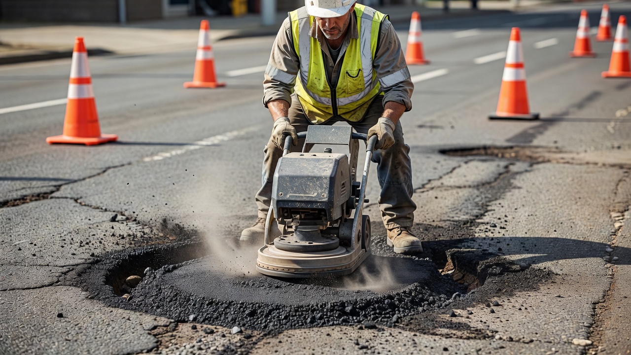
Asphalt patching encompasses throw-and-roll, semi-permanent, spray injection, and full-depth repair methods for localized pavement defects. Patch condition and durability are recurring inspection items — poor patches become new defects.
Asphalt Patching and Pothole Repair
Definition of Asphalt Patching
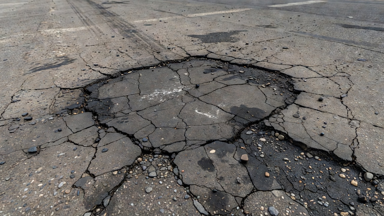
Asphalt patching is a corrective maintenance activity that involves the localized repair of discrete defects on asphalt pavement surfaces. It is one of the most frequently performed pavement maintenance operations across the entire transportation infrastructure spectrum, from municipal roads and highways to airport runways, taxiways, and aprons. The fundamental objective of patching is to restore the structural integrity, surface uniformity, and skid resistance of pavement that has been compromised by potholes, spalls, edge cracking, utility cuts, or localized structural failures.
As defined in FAA Advisory Circular AC 150/5380-6C (Airport Pavement Maintenance and Rehabilitation), patching is a recurring maintenance activity essential to preserving pavement load-carrying capacity, ride quality, surface friction, and — critically for aviation operations — minimizing foreign object debris (FOD) hazards. A pothole that goes unrepaired can rapidly enlarge through traffic loading, water infiltration, and freeze-thaw cycling, ultimately compromising the underlying base and subgrade layers.
Patching occupies a unique position in the pavement maintenance hierarchy: it is simultaneously a corrective action (addressing an existing defect), a preventive measure (stopping further deterioration), and — when performed poorly — a potential source of new defects. A patch that debonds, settles, or ravels becomes a distress in its own right, requiring re-repair and potentially causing FOD on airfield pavements.
The efficacy of any asphalt patch depends on the interplay of five critical factors:
Material selection — matching the patching material to the climate, traffic level, and defect type
Preparation quality — proper cutting, cleaning, drying, and tack coating of the repair cavity
Placement technique — correct material placement in lifts of appropriate thickness
Compaction — achieving target density to resist water intrusion and traffic loading
Edge bonding — creating a durable, watertight seal between patch and parent pavement
This glossary article examines each of these factors in detail, covering patch types, materials, equipment, inspection criteria, and the role of patching within airport pavement management systems.
Patch Types
Asphalt patching methods range from quick temporary repairs intended to last weeks to permanent structural restoration designed for multi-year service life. The selection of an appropriate patch type depends on the severity and cause of the defect, traffic levels, weather conditions at the time of repair, available equipment, and performance expectations.
Localized potholes on roads and airfield pavements
Medium
Spray Injection
2–5 years
Combination patching truck with air/emulsion/aggregate system
Potholes, edge cracks, surface spalls
Medium
Infrared
2–5 years
Infrared heater unit, rake, compactor
Surface failures, utility cuts, patch reclamation
Medium-High
Full-Depth
5–10+ years
Saw-cut, milling machine, paver (for large areas), rollers
Structural failures, base failure, deep potholes
High
Throw-and-Roll Patching
Throw-and-roll — also referred to as throw-and-go or emergency patching — is the simplest and least durable asphalt patching method. It is intended exclusively as a temporary measure to eliminate immediate safety hazards and prevent rapid pothole enlargement until a permanent repair can be scheduled.
Procedure:
The pothole is cleaned of loose debris, standing water, and ice using shovels, brooms, or compressed air. Cleaning is typically minimal compared to other methods.
Cold mix asphalt — often stockpile material — is dumped directly into the pothole from a truck or wheelbarrow.
Workers spread the material with shovels, mounding it slightly above grade to allow for traffic compaction.
Vehicle traffic over the patch provides the compaction — rolling the patch into place. In controlled or low-traffic areas, a truck tire or hand tamper may be used.
The primary advantages of throw-and-roll patching are speed, minimal equipment needs, and the ability to perform repairs in cold or wet conditions where other methods are impractical. However, the lack of proper cavity preparation, edge cutting, tack coat, and mechanical compaction produces patches that are prone to rapid failure through raveling, edge deterioration, and material displacement.
On airport pavements, throw-and-roll patching is rarely acceptable for operational surfaces (runways, taxiways) due to FOD risks from loose aggregate and the potential for patch material to dislodge under aircraft tire loads. It may be used as an interim measure on low-traffic service roads or apron edges pending permanent repair.
Semi-Permanent Patching
Semi-permanent patching is the most widely specified pothole repair method for roads and airfield pavements where a durable, medium-term repair is required. It involves cutting a rectangular hole around the defect, removing distressed material, applying tack coat, placing patching material in lifts, and compacting mechanically.
Procedure:
Cutting: The pothole is cut into a rectangular or square shape using a saw, pavement breaker, or milling head. The cut extends a minimum of 6–12 inches beyond the visible distress into sound pavement. Vertical, unfractured (clean, straight) edges are essential for good bonding.
Removal: All distressed material, loose aggregate, and debris are removed from the cavity. The depth extends to the bottom of the distressed layer — typically through the full asphalt thickness for structural potholes.
Cleaning: The cavity is thoroughly cleaned using compressed air, a leaf blower, or brooms. All loose particles, dust, and moisture must be removed. Standing water must be eliminated — patching into wet cavities is a primary cause of premature failure.
Tack Coat: A uniform application of tack coat (typically CSS-1, SS-1, or polymer-modified emulsion) is applied to the vertical walls and bottom of the cavity. The tack coat must be allowed to break (change from brown to black) before material placement. Tack coat rates typically range from 0.05 to 0.15 gallons per square yard depending on surface condition.
Placement: Hot mix asphalt (HMA) or polymer-modified cold mix is placed in the cavity. For depths exceeding 3 inches, material is placed in multiple lifts, each compacted separately. The material is mounded slightly to account for compaction.
Compaction: A vibratory plate compactor, tandem roller, or pneumatic tire roller is used to compact the patch. Compaction proceeds from the edges toward the center to seal the patch-pavement interface. The finished patch surface should be flush with the surrounding pavement.
Semi-permanent patching is the recommended method for airport pavement pothole repairs in FAA guidance, provided the surrounding pavement is structurally sound. When properly executed with quality materials, service life of 2 to 3 years is achievable.
Spray Injection Patching
Spray injection patching (also called patcher truck or spray patching) is a mechanized method that combines compressed air, emulsified asphalt binder, and aggregate in a single continuous operation. It is the fastest patching method available, typically completing a repair in 30 to 90 seconds per pothole.
Procedure:
The patching truck positions over the pothole. High-pressure air (100–200 psi) is directed into the cavity to clean out debris, water, and loose material.
The operator actuates a nozzle that sprays a layer of emulsified asphalt tack coat onto the cavity walls and bottom.
A stream of aggregate (typically ⅜-inch to ½-inch washed stone) is blown into the cavity simultaneously with additional emulsified asphalt, creating a coated aggregate matrix that fills the pothole.
The final step applies a squeegee coat or top seal of emulsified asphalt over the patch surface to seal it and promote skid resistance.
Compaction occurs partially from the force of the injected material and partially from traffic. Some spray injection trucks include an integrated drag shoe or vibratory screed for additional compaction.
Spray injection patching offers several distinct advantages:
Speed: A crew can repair 100–200 potholes per day
No heating: All materials are cold; no hot mix logistics required
Water resistance: The emulsion-coating process creates a flexible, waterproof patch that bonds well to cavity surfaces
Minimal waste: Material is precisely metered; excess is collected and reused
Year-round capability: Can be performed in temperatures as low as 30°F with appropriate emulsion formulations
The primary limitation of spray injection patching is that it does not achieve the same density as mechanically compacted hot mix patches. The patch is more flexible and permeable than semi-permanent patches. In airport applications, spray injection is suitable for taxiway edges, apron areas, and access roads but may not be acceptable on runway surfaces where maximum density and FOD resistance are required.
Infrared Patching
Infrared patching uses infrared heat energy to soften the existing pavement surface, allowing new patching material to be thermally bonded to the existing asphalt rather than relying solely on tack coat adhesion. This method is particularly effective for repairing surface-level defects, utility cuts, and adjusting patch surfaces.
Procedure:
An infrared heating unit — typically a gas-fired ceramic panel or electric emitter mounted on a trailer or truck — is positioned over the repair area.
The pavement surface is heated to approximately 300–350°F, softening the existing asphalt to a depth of 1 to 2 inches.
The heated pavement is scarified (raked) to create a uniform, workable surface.
New hot mix asphalt is added to fill any depressions, and the blended material (recycled existing plus new) is raked to grade.
The area is compacted with a vibratory plate compactor or roller.
The key advantage of infrared patching is the creation of a thermal bond between the patch and parent pavement — a monolithic joint that is significantly more resistant to water intrusion and edge deterioration than cold joints created by tack coat alone. Because the existing pavement material is recycled in place, there is minimal waste.
Infrared patching is limited by depth — it is not suitable for structural repairs extending deeper than 2–3 inches without combining with other methods. It also requires dry conditions and ambient temperatures above 40°F for optimal results. On airport pavements, infrared patching is commonly used for repairing surface raveling, adjusting settled utility cuts, and rehabilitating deteriorated patch areas.
Full-Depth Patching
Full-depth patching is the most comprehensive and durable asphalt repair method. As the name implies, the full depth of the asphalt pavement structure is removed and replaced, including the surface course, binder course, and base course down to the subgrade if necessary. Full-depth patching is indicated when the pavement failure extends through the full asphalt thickness or when base or subgrade failure has occurred.
Procedure:
Define the repair area: The patch boundaries are marked in a rectangular pattern extending at least 12–24 inches beyond the visible distress into structurally sound pavement.
Saw-cutting: A concrete/asphalt saw cuts along the marked boundaries to a depth equal to the full asphalt thickness. Vertical, clean edges are critical.
Removal: The asphalt material within the cut area is removed using a milling machine, pavement breaker, or excavator. The material may be recycled.
Base evaluation: The exposed base material is inspected. If the base is contaminated, saturated, or structurally inadequate, it is removed and replaced with compacted aggregate base course, typically to a depth of 6–12 inches depending on design requirements.
Base compaction: The base material is placed in lifts and compacted to minimum 95% of maximum dry density (per ASTM D698 or D1557).
Tack coat: Tack coat is applied to the vertical walls and the base surface.
Asphalt placement: Hot mix asphalt is placed in lifts. For typical airport pavement structures, lift thicknesses are 2–3 inches per layer. Each lift is compacted before the next is placed.
Compaction: A breakdown roller (steel vibratory), intermediate roller (pneumatic tire), and finish roller (static steel) are used to achieve target density — typically 96–98% of laboratory density per Marshall or Superpave mix design criteria.
Surface finish: The final surface is checked with a straightedge for conformity to grade. The patch must be flush with the surrounding pavement to prevent ponding and ride quality issues.
Full-depth patches, when properly designed and constructed, provide service lives of 5 to 10 years or longer. They are the standard of care for structural pavement repairs on airport runways, taxiways, and high-traffic apron areas where failure of a patch would create operational disruptions or FOD hazards.
Material Selection
The choice of patching material is a critical determinant of patch performance. Materials must be matched to the repair method, ambient and pavement temperature at the time of installation, traffic loading, and expected service life.
Hot Mix Asphalt (HMA)
Hot mix asphalt is the preferred material for semi-permanent and full-depth patching. HMA consists of well-graded aggregate coated with heated asphalt cement binder, produced at temperatures between 275°F and 325°F at a central plant. The heat provides workability during placement and allows compaction to high density.
For airport pavement patching, HMA is typically specified to meet the same mix design criteria as the original pavement — a Marshall stability of at least 1,800 pounds for light aircraft traffic and 2,400 pounds or higher for transport aircraft traffic, per FAA standards.
Advantages of HMA include:
Highest achievable density and strength
Excellent resistance to raveling and wear
Rapid traffic opening (can be opened as soon as patch cools to 175°F or below)
Long service life when properly compacted
Disadvantages include:
Requires hot mix plant access and delivery logistics
Cannot be placed in cold weather (typically below 40°F) without special accommodations
Rapid cooling limits working time in cold conditions
Higher equipment and material costs than cold mix
Cold Mix Asphalt
Cold mix asphalt is produced using emulsified or cutback asphalt binders that remain workable at ambient temperatures. It is the primary material for throw-and-roll patching and is also used in spray injection systems and stockpile patching materials.
Three categories of cold mix are common:
Emulsion-based cold mix: Uses emulsified asphalt (typically CSS-1, CMS-2, or SS-1) as the binder. Aggregate is coated at ambient temperature. The material cures as water evaporates from the emulsion, leaving the asphalt coating.
Cutback-based cold mix: Uses asphalt cutback with solvents (kerosene or mineral spirits) to achieve workability. Cure occurs as solvents evaporate. Less common in modern practice due to environmental and worker safety concerns.
Polymer-modified cold mix: Incorporates polymer additives (SBS, SBR, latex) to improve binder properties, enhancing adhesion, cohesion, flexibility, and temperature susceptibility. These materials significantly outperform conventional cold mixes.
The PennDOT LTAP Technical Sheet #185 emphasizes that polymer-modified cold mixes give superior exterior adhesion and cohesion compared to conventional cold mixes. They are more resistant to traffic abrasion, maintain flexibility at low temperatures, and resist deformation at high temperatures.
Cold mix patching materials can be placed in a wider temperature range (down to 20°F for some formulations) than hot mix, making them suitable for winter emergency repairs. However, cold mixes do not achieve the density or strength of hot mix, and their service life is shorter.
Polymer-Modified Materials
The addition of polymers to asphalt binders has significantly improved patching material performance. Polymer modification enhances:
Adhesion: Better bond to cavity walls and existing pavement surfaces
Cohesion: Greater internal strength within the patching material
Elastic recovery: Ability to deform under load and return to original shape
Temperature susceptibility: Reduced stiffness at low temperatures, reduced rutting at high temperatures
Moisture resistance: Improved resistance to stripping and water damage
Common polymers used in patching materials include styrene-butadiene-styrene (SBS), styrene-butadiene rubber (SBR), ethylene vinyl acetate (EVA), and latex emulsions. Polymer-modified cold mixes are now considered standard for quality semi-permanent patching, and polymer-modified emulsions are widely used in spray injection patching systems.
Climate Considerations
Material selection must account for the climate conditions at the time of placement and throughout the expected service life:
Climate Factor
Material Consideration
Cold weather placement (<40°F)
Use polymer-modified cold mix or specialty winter-grade HMA. Avoid conventional HMA. Heat aggregate or use warm mix additives if HMA is required.
Wet conditions
Use emulsion-based materials with rapid-set characteristics. Ensure cavity is dried before placement. Avoid cutback materials in wet cavities.
Freeze-thaw cycling
Use polymer-modified materials with high flexibility. Ensure patches are well-sealed at edges to prevent water infiltration. Full-depth patches perform best.
Hot climates
Use high-stability HMA with stiff binder grades. Avoid cutback materials that may bleed. Ensure compaction is achieved before material cools.
High traffic (aircraft loads)
Use HMA or polymer-modified hot mix. Full-depth patches with mechanical compaction are recommended. Avoid thin surface patches.
Patch Preparation
Proper preparation of the repair cavity is arguably the most important determinant of patch performance. Inadequate preparation is the most common cause of premature patch failure, regardless of the material or method used.
Cutting
The repair area must be cut to create clean, vertical edges that expose sound pavement on all sides of the defect. Key requirements:
Shape: Rectangular or square patches perform better than irregular shapes. Acute angles concentrate stress and are prone to cracking. The PennDOT LTAP guide recommends extending the cut 12–24 inches beyond the visible distress on all sides.
Edge verticality: Saw-cut edges should be vertical, not feathered or tapered. Vertical edges maximize the bonding surface area for tack coat and provide mechanical interlock.
Depth: The cut should extend through the full depth of the distressed layer. For potholes caused by structural failure, this means removing the entire asphalt layer down to the base.
Equipment: Masonry saws, asphalt cutters, or pavement breakers with spade bits are used. For large patches (>10 square feet), milling machines may be more efficient.
Cleaning
After cutting and material removal, the cavity must be thoroughly cleaned:
Loose debris removal: All loose aggregate, broken pavement pieces, dirt, and vegetation are removed.
Dust removal: Compressed air (100+ psi) is used to blow dust from the cavity walls and bottom. Leaf blowers are acceptable for large cavities but less effective for removing fines from textured surfaces.
Moisture elimination: Standing water must be completely removed. Patches placed over wet cavities trap moisture that leads to debonding, stripping, and freeze-thaw damage. A propane torch or hot air lance can be used to dry cavities when wet conditions exist.
Oil or contamination removal: Hydrocarbon-contaminated surfaces should be cleaned with detergents or grinding to ensure tack coat adhesion.
Tack Coat Application
Tack coat creates the bonding layer between the existing pavement and the new patching material. Without tack coat, the patch relies entirely on mechanical interlock, which is insufficient for durable performance.
Tack coat materials:
CSS-1 (cationic slow-setting emulsion) — most common for patching
SS-1 (anionic slow-setting emulsion)
Polymer-modified emulsions (PCE, PME) — superior bonding for high-traffic patches
Asphalt binder (PG 64-22 or similar) — used for hot-applied tack
Trackless tack coats — formulated to resist picking up on tires and equipment
Application rates:
General rate: 0.05 to 0.15 gallons per square yard
Porous or milled surfaces: 0.10 to 0.25 gallons per square yard
Dense, tight surfaces: 0.03 to 0.05 gallons per square yard
Application method:
Tack coat must be applied uniformly to the vertical walls and the bottom of the cavity. Application methods include:
Hand spraying with a wand applicator connected to a distributor truck
Pressure sprayer for small patches
Brush application for very small areas
Critical waiting period:
The tack coat must be allowed to break — the point at which the emulsion changes from brown to black and becomes tacky — before placing the patching material. If material is placed before the emulsion breaks, the water in the emulsion acts as a bond-breaking layer. If the tack coat is allowed to fully cure (dry to the touch), it loses its adhesive properties. The window between breaking and curing varies with temperature and humidity — typically 5 to 30 minutes.
Compaction Requirements
Compaction is the process of densifying the patching material to achieve a stable, water-resistant mass with sufficient load-bearing capacity. Inadequate compaction is the second most common cause of patch failure (after poor preparation).
Why Compaction Matters
Density: Compacted asphalt achieves target density (typically 92–98% of theoretical maximum density) that resists deformation under load.
Air voids: Proper compaction reduces air voids to an optimal range (3–7% for HMA). Too many voids allow water and air infiltration, leading to oxidation, stripping, and raveling. Too few voids can lead to bleeding and rutting.
Interlock: Compaction forces aggregate particles into close contact, developing internal friction and mechanical interlock that provides structural strength.
Water resistance: Dense material is less permeable to water, protecting the base and subgrade from moisture damage.
Compaction Equipment
Vibratory plate compactors:
The most common compaction tool for patches. Typical requirements:
Plate size: at least 18 × 24 inches for patch work
Centrifugal force: 3,000–8,000 pounds
Frequency: 4,000–6,000 vibrations per minute
Coverage: 4–6 passes per lift
Steel drum rollers:
Used for larger patches and full-depth repairs:
Tandem vibratory rollers: 2–4 tons for patch work
Static rollers: for finish rolling and sealing the surface
Pass pattern: start at edges, work toward center
Pneumatic tire rollers:
Rubber-tired rollers provide kneading action that seals the surface and achieves high density in thick lifts:
Tire pressure: 70–100 psi
Weight: 5–15 tons for patch applications
Hand tampers and jumping jacks:
Used for confined areas where power equipment cannot reach:
Provide lower density than mechanical compactors
Acceptable only for very small patches or confined areas
Compaction Best Practices
Temperature: Compact HMA while it is hot — compaction must be complete before the mix cools below 175°F (for HMA).
Lift thickness: Each lift should not exceed 3 inches for effective compaction. Deeper patches require multiple lifts.
Edge start: Begin compaction at the patch edges to seal the patch-pavement interface, then move toward the center in overlapping passes.
Grade control: Place material approximately ¼ inch above grade to account for compaction. The finished patch should be flush with the surrounding pavement.
Traffic opening: Allow the patch to cool sufficiently before opening to traffic. HMA patches can generally be opened when the surface temperature drops below 175°F — typically 15–30 minutes depending on ambient conditions.
{{
Patch Edge Bonding
The interface between the patch and the parent pavement is the most vulnerable part of any asphalt repair. Edge bonding — the adhesion and sealing of this interface — is critical to patch durability.
Why Edge Bonding Fails
Insufficient tack coat: Inadequate or no tack coat on vertical walls leaves the interface unbonded, creating a preferential path for water infiltration.
Dust contamination: Dust on the cavity walls prevents tack coat adhesion. Even a thin layer of fines reduces bond strength by 50% or more.
Moisture at interface: Water present at the interface during patching prevents bituminous adhesion and can lead to stripping.
Thermal incompatibility: Differential thermal expansion and contraction between patch and parent pavement stresses the bond line, particularly in freeze-thaw environments.
Traffic loading: Shear stresses at the patch edge from braking, turning, or accelerating traffic can debond the interface.
Best Practices for Edge Bonding
Saw-cut vertical edges: Vertical faces maximize the bonding surface and provide mechanical interlock.
Apply tack coat to edges: Use a wand applicator to ensure complete coverage of all vertical faces.
Pre-coat edges with emulsion: For spray injection patching, the initial blast of emulsion coats the cavity walls before aggregate is introduced.
Compact from edges inward: Starting compaction at the patch edge seats the material against the vertical face, promoting intimate contact.
Seal the joint surface: After compaction, a light application of emulsified asphalt or joint sealant along the patch perimeter provides additional water protection.
A properly bonded patch edge should be indistinguishable from the surrounding pavement surface. Any visible crack, gap, or depression at the patch perimeter indicates edge bonding failure that will rapidly progress.
Patch Durability and Failure Modes
Asphalt patches are inherently less durable than the original pavement — they introduce joints, use higher volumes of binder, rely on adhesive bonds to existing material, and are often placed under less-than-ideal conditions. Understanding how patches fail enables better material selection, preparation, and inspection.
{{
Edge Deterioration
Edge deterioration — also called edge cracking or joint raveling — is the breakdown of the patch boundary. It begins as a fine crack at the patch-pavement interface and progresses to spalling, aggregate loss, and open joints.
Causes:
Inadequate edge bond from insufficient tack coat
Water infiltration at the interface followed by freeze-thaw action
Traffic-induced shear at the patch edge
Thermal movement differential between patch and parent pavement
Dust or moisture contamination on the cavity walls during installation
Severity classification (per ACRP Report 159):
Low: Fine hairline crack at the interface with no spalling. Less than ¼ inch wide.
Medium: Open crack with minor raveling or spalling. ¼ to ½ inch wide.
High: Significant spalling, aggregate loss, or open gap exceeding ½ inch. The patch edge is clearly separated from surrounding pavement.
Edge deterioration is the most common patch failure mode. Because it creates a direct path for water to enter the pavement structure, it accelerates all other failure mechanisms.
Settlement
Settlement is the vertical depression of a patch relative to the surrounding pavement surface. It results from consolidation of the patching material, the underlying base, or both.
Causes:
Inadequate compaction of the patching material
Compaction of underlying base or subgrade from traffic loading
Base material loss through water erosion
Insufficient patch thickness
Effects:
Ride quality degradation — creates a bump or dip at runway/taxiway speeds
Water ponding in the depressed area, accelerating deterioration
Traffic-induced impact loading on the patch edges
In severe cases, FOD risk from broken patch edges
Severity classification:
Low: Settlement less than ½ inch. Minor ride quality effect.
Medium: Settlement ½ to 1 inch. Noticeable ride quality impact.
High: Settlement exceeding 1 inch. Significant ride quality impact and FOD risk.
Raveling
Raveling is the progressive loss of aggregate from the patch surface downward. It is a surface-initiated failure that can expose underlying layers.
Causes:
Insufficient binder content in the patching material
Poor aggregate gradation
Binder aging or oxidation
Inadequate compaction leaving high air voids
Water intrusion and stripping of binder from aggregate
Cold weather placement preventing proper material consolidation
Severity classification:
Low: Loss of fine aggregate only. Surface texture is slightly rough.
Medium: Loss of some coarse aggregate. Surface is noticeably pitted.
High: Extensive loss of coarse aggregate. Deep pits and exposed coarse aggregate.
Raveling on airport pavements is a FOD hazard — loose aggregate particles can be ingested by jet engines or damage propeller blades and airframe surfaces.
Debonding
Debonding — also called delamination — is the separation of the patch layer from the underlying pavement or base surface. Unlike edge deterioration which occurs at the perimeter, debonding involves internal separation across the patch area.
Causes:
No tack coat or insufficient tack coat on the cavity bottom
Tack coat broken before material placement (emulsion cured to dry)
Moisture trapped between the patch and the underlying surface
Dust or dirt on the base surface before patching
Thermal shock from placing hot mix on a cold, wet base
Incompatible materials between patch and existing pavement
Detection:
Hollow sound when tapped with a hammer or metal rod
Surface cracking in a pattern indicating separation
Pumping of water or fines from under the patch under traffic loading
Progressive cracking and settlement
Debonding is particularly dangerous on airport pavements because the separated layer can dislodge under aircraft loads, creating large FOD pieces.
Other Failure Modes
Patch cracking: Cracking within the patch body from thermal contraction, reflective cracking from underlying pavement movement, or structural loading.
Bleeding: Excess binder rising to the patch surface, creating a slick, low-friction surface. Caused by binder-rich mix, low air voids, or over-compaction.
Pumping: The expulsion of water and fine material from under or around the patch under traffic loads, indicating debonding or base failure.
Patch blow-up: Compressive buckling and shoving of the patch pavement, typically occurring in hot weather when expansion forces exceed the patch-pavement bond strength.
Inspection of Patches per PCI Standards
The Pavement Condition Index (PCI) methodology, standardized in ASTM D5340 Standard Test Method for Airport Pavement Condition Index Surveys, provides a rigorous framework for evaluating patch condition as part of overall pavement assessment.
Patch as a Distress Type
In PCI surveys, patches are classified as a distinct asphalt pavement distress type. The inspector evaluates each patch in the sample unit and assigns a severity level based on observable condition. Critically, patches that are in good condition — performing as intended without deterioration — are not counted as distress. Only patches showing deterioration are deducted from the PCI score.
Severity Levels per ASTM D5340
Low Severity (L):
Patch is generally sound and performing well.
Minor surface raveling or cracking may be present.
No settlement or edge deterioration.
No FOD risk.
Does not require immediate repair.
Medium Severity (M):
Moderate deterioration of the patch.
Surface cracking, raveling, or edge cracking affecting ride quality.
Settlement up to ½ inch.
Moderate spalling at patch edges.
May require repair within the next maintenance cycle.
High Severity (H):
Severe deterioration of the patch.
Significant settlement (exceeding ½ inch).
Deep cracking, raveling, or spalling.
Debonding evident (hollow sound, pumping).
FOD risk present.
Requires immediate repair or replacement.
Distress Density Calculation
For PCI calculation, the distress density is computed as:
The density and severity level are used with the appropriate PCI deduct curve (found in ASTM D5340) to determine the deduct value. This value is subtracted from the maximum PCI score (100) to determine the condition index.
Inspection Procedures
Visual survey: The inspector identifies all patches within the sample unit.
Measurement: Each patch area is measured (length × width) and recorded.
Severity assessment: Each patch is assigned a severity based on observed deterioration.
Documentation: Photographs and notes document patch condition for verification and trend tracking.
Density calculation: The ratio of deteriorated patch area to sample unit area is computed.
Deduct value determination: The deduct curve appropriate for asphalt patches is consulted.
Score adjustment: The total deduct value is subtracted from the sample unit PCI.
For detailed reporting, the ACRP Report 159 Field Guide for Airport Pavement Maintenance recommends documenting not only severity but also the specific deterioration type observed (edge deterioration, settlement, raveling, debonding) to guide maintenance planning.
Patch as Asset Condition Indicator
The condition of patches on an airfield pavement provides valuable insight into the overall health of the pavement structure and the effectiveness of the maintenance program.
What Patches Reveal About Pavement Condition
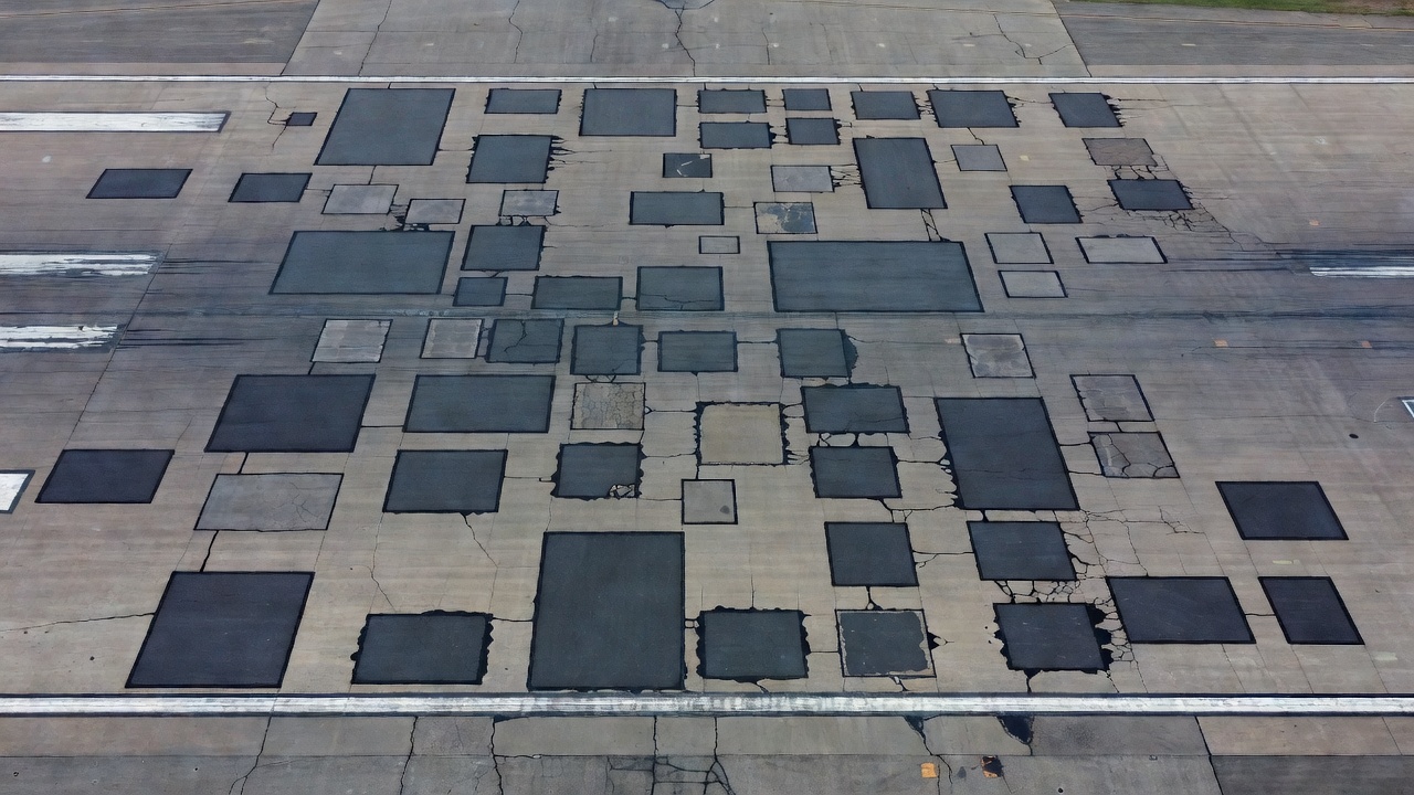
Frequency of patching: A pavement section with numerous patches indicates underlying structural weakness or widespread fatigue. The presence of multiple patches suggests that the pavement is approaching the end of its service life and may require rehabilitation rather than continued spot repairs.
Patch deterioration rate: The speed at which patches fail reveals the severity of the underlying distress. If new patches deteriorate within months, the pavement section has active structural issues that demand investigation — base failure, drainage problems, or subgrade instability.
Patch type in use: The type of patches present reflects the maintenance philosophy. Full-depth patches indicate a strategy of structural restoration. Spray injection or throw-and-roll patches suggest temporary repairs, possibly indicating budget constraints or emergency response operations.
Patch condition distribution: Clusters of failed patches at specific locations (runway ends, taxiway curves, apron areas) may indicate localized loading conditions, drainage issues, or construction deficiencies that require targeted investigation.
Patches in Pavement Management Systems
In a pavement management system (PMS), patches are tracked as both a distress type and a maintenance action:
As a distress: Deteriorated patches reduce the PCI score and trigger maintenance recommendations.
As a maintenance record: The installation date, type, material, and contractor of each patch should be recorded in the asset database to track performance and refine maintenance strategies.
The relationship between patch performance and pavement section condition can be modeled to predict optimal timing for rehabilitation:
Patch rate acceleration: When the rate of new patching increases year-over-year by more than 20%, it signals that the pavement section is approaching the point where rehabilitation is more cost-effective than continued patching.
Patch failure ratio: The ratio of failed patches to total patches in a section, tracked over time, is a leading indicator of structural deterioration.
Patching in Airport Pavements
Airport pavement patching operates under stricter standards than road patching due to the unique demands of aircraft operations: high tire pressures, FOD sensitivity, and the operational consequences of pavement failure.
FAA Requirements (AC 150/5380-6C)
FAA Advisory Circular AC 150/5380-6C (Airport Pavement Maintenance and Rehabilitation) provides comprehensive guidance on airport pavement patching:
Maintenance responsibility: Airport operators are responsible for maintaining pavements in a condition that is safe for aircraft operations. Patching is a recurring maintenance activity.
Timeliness: Patching should be performed promptly when defects develop. Delayed patching allows water infiltration and progressive failure.
Materials: Materials used for patching should be compatible with the existing pavement. The use of HMA materials meeting FAA mix design criteria (Item P-401 for asphalt pavements) is recommended for permanent repairs.
FOD prevention: All patching operations must be conducted with strict FOD control measures. Loose material must be swept immediately after completion. Patches must be inspected after first traffic pass to verify integrity.
Surface friction: Patched areas must provide friction characteristics equivalent to the surrounding pavement. Excess binder on the surface must be blotted or removed.
Grade control: Patches must be flush with the surrounding pavement. Depressions or bumps exceeding ¼ inch on runways require corrective action.
ICAO Standards
The International Civil Aviation Organization (ICAO) — through Annex 14 to the Convention on International Civil Aviation and associated documents — establishes standards for airport pavement condition:
Surface condition: Runway surfaces must be maintained in a condition that does not impair the safe operation of aircraft. Patches that create uneven surfaces or loose material are non-compliant.
FOD management: ICAO requires aerodrome operators to implement FOD management programs. Failed patches are a primary FOD source that must be controlled through inspection and timely repair.
Routine inspection: ICAO recommends daily inspections of movement areas. Patches showing distress must be identified and scheduled for repair.
Reporting: Pavement condition, including patch condition, is part of the aerodrome reporting system for safety management.
{{
Special Considerations for Airfield Patching
Runway patches:
Must withstand high tire pressures (up to 200 psi for large transport aircraft)
Must provide uniform friction across the patch area
Cannot create raised edges or depressions
Are subject to rigorous FOD inspection after each repair
Ideally scheduled during low-traffic periods or overnight
Taxiway patches:
Subject to turning loads and shear stresses at curves
Edge bonding is particularly critical where aircraft nose-wheel steering applies lateral forces
Must accommodate full pavement structural section
Apron patches:
Exposed to jet blast, fuel spills, and heavy static loads
Materials must be resistant to hydrocarbon damage
Surface must be skid-resistant for ground support equipment
Inspected regularly for debonding from fuel infiltration
Safety area patches:
Patches in runway safety areas (RSAs) and blast pads must maintain load-bearing capacity for safety equipment and arresting systems
Must be flush to prevent tripping hazards for personnel
Subject to less frequent but equally rigorous inspection
Patching Strategy and Pavement Management
A systematic approach to patching — rather than reactive, ad-hoc repairs — produces better outcomes, lower lifecycle costs, and improved pavement performance.
Developing a Patching Strategy
Inventory and assessment: Conduct a comprehensive PCI survey (per ASTM D5340) to document all patches and their condition. Record patch type, date of installation, material used, and deterioration status.
Performance tracking: Monitor patch deterioration rates to identify sections where patches fail prematurely, indicating underlying structural issues.
Method selection criteria: Establish a decision matrix for patch type selection based on:
Defect type and cause (surface vs. structural)
Traffic level (aircraft types and frequency)
Weather conditions at time of repair
Expected service life
Available equipment and materials
Budget constraints
Quality control: Implement inspection checklists for patching operations. Verify compliance with preparation, placement, and compaction specifications. Reject non-compliant work.
Seasonal planning: Schedule major patching programs during favorable weather windows. Maintain capability for emergency patching year-round through appropriate cold-weather materials and methods.
Economic Considerations
The economic analysis of patching strategies typically compares the cost of different patch types against their expected service life:
Patch Type
Unit Cost (per sq. ft.)
Service Life
Annualized Cost
Throw-and-Roll
$2–$4
3–6 months
$8–$16 per sq. ft./year
Semi-Permanent (cold mix)
$5–$10
1–2 years
$2.50–$10 per sq. ft./year
Semi-Permanent (HMA)
$8–$15
2–3 years
$2.67–$7.50 per sq. ft./year
Spray Injection
$4–$8
2–5 years
$0.80–$4 per sq. ft./year
Full-Depth
$15–$30
5–10 years
$1.50–$6 per sq. ft./year
While full-depth patching has the highest initial cost, its lowest annualized cost makes it the most economical option for pavements where long-term performance is required. Throw-and-roll patching, despite its low unit cost, has the highest annualized cost due to frequent reapplication.
Integration with Pavement Management Systems
Effective patching is part of a comprehensive pavement management approach:
Maintenance triggers: Define PCI thresholds that trigger patching. For critical airfield pavements (runways), patches showing medium or high severity should be scheduled for repair within defined timeframes (e.g., 30 days for medium, 7 days for high).
Work planning: Group patches by location and priority to maximize crew efficiency. One crew can repair 30–50 potholes per day using semi-permanent methods or 100–200 per day using spray injection.
Performance feedback: Track patch performance by contractor, method, and material to identify best-value practices. Use data to refine specifications and contractor selection.
Rehabilitation triggers: Monitor patch frequency in each pavement section. When a section requires more than 10–15% patching, evaluate whether overlay or reconstruction is more cost-effective than continued patching.
Lifecycle planning: Include patching costs in pavement lifecycle models. The optimal time for rehabilitation is typically when annual patching costs exceed the annualized cost of rehabilitation.
Emerging Technologies
Digital inspection and AI-powered condition assessment are transforming pavement patching management:
Computer vision patching detection: AI models trained on pavement imagery can automatically detect patches, classify their condition, and track deterioration over time without requiring manual surveys.
Asset management integration: Digital platforms like TarmacView enable operators to link patch records with inspection data, maintenance history, and pavement section performance, providing a complete picture of pavement health.
Predictive analytics: Historical patch performance data can be used to predict when patches will fail and optimize maintenance scheduling, reducing emergency repairs and extending pavement service life.
Asphalt patching is far more than a routine maintenance task — it is a critical pavement preservation activity that directly impacts safety, operational efficiency, and infrastructure lifecycle costs. The difference between a patch that lasts 6 months and one that lasts 5 years lies not in the cost of materials but in the rigor of preparation, the appropriateness of method selection, and the quality of execution.
For airport operators, the stakes are particularly high. A failed patch on a runway is not merely a maintenance inconvenience — it is a potential FOD hazard that can cause jet engine damage, tire failure, or airframe impact. The FAA and ICAO standards reflect this reality through stringent requirements for patch materials, methods, and inspection.
The most cost-effective patching strategy is not necessarily the cheapest initial repair but the one that correctly diagnoses the cause of the defect, selects the appropriate repair method, executes it with quality materials and workmanship, and tracks performance to inform future maintenance decisions. When patching is integrated into a comprehensive pavement management system — supported by digital inspection tools and performance data — it becomes a strategic maintenance function that maximizes pavement service life and minimizes lifecycle costs.
Frequently Asked Questions
Throw-and-roll is a temporary, low-cost method where cold mix asphalt is dumped into a pothole, spread with shovels, and compacted by vehicle traffic. It requires minimal equipment and can be performed rapidly, but patches typically last only weeks to a few months. Full-depth patching is a permanent repair method that removes the entire pavement structure down to the subgrade, replaces base material if damaged, and installs new hot mix asphalt in lifts with mechanical compaction. It requires saw-cutting, milling equipment, pavers, and rollers, and patches can last 5 to 10 years or more when properly executed. The choice depends on the severity of the underlying distress, pavement criticality, budget, and desired service life.
Patch durability varies significantly by method and conditions. Throw-and-roll patches may last 1 to 6 months. Semi-permanent patches typically last 1 to 3 years. Spray injection patches can last 2 to 5 years with proper application. Infrared patches, when well-bonded, last 2 to 5 years. Full-depth patches represent the most durable option, lasting 5 to 10 years or longer. Factors that reduce patch life include poor edge bonding, inadequate compaction, moisture infiltration, freeze-thaw cycling, heavy traffic loads, and deferred maintenance of surrounding pavement. In airport environments, patches on runways and taxiways face higher performance expectations due to FOD (foreign object debris) risks, and any patch showing distress is typically scheduled for replacement within the next maintenance cycle.
Asphalt patches fail through several distinct mechanisms: edge deterioration occurs when the bond between patch material and surrounding pavement breaks down, allowing water infiltration and raveling at the joint. Settlement results from inadequate compaction of patch material or underlying base failure, creating depressions that collect water and cause ride quality issues. Raveling is the progressive loss of aggregate from the patch surface due to poor mix design, insufficient binder content, or binder aging. Debonding is the separation of the patch layer from the underlying pavement or base, often caused by inadequate tack coat, moisture trapped beneath the patch, or thermal incompatibility between patch and existing material. Other failure causes include improper patch shape (non-rectangular patches with acute angles are prone to cracking), inadequate depth, and application during cold or wet weather.
In PCI surveys conducted per ASTM D5340, patches are inspected as a distinct asphalt distress type. Patch condition is classified by severity — low, medium, or high — based on size and condition. Low severity patches are generally sound but may show minor surface raveling or slight edge cracking. Medium severity patches exhibit moderate deterioration, cracking, or settlement affecting ride quality. High severity patches show severe distress including deep cracking, significant settlement, raveling, or material loss that creates FOD risk. The distress density is calculated as the ratio of the patched area (at each severity level) to the total sample unit area. This density, combined with severity, determines the deduct value that reduces the PCI score. Patches that are in good condition and performing well do not necessarily count as distress — only patches showing deterioration are deducted.
Digitize Your Pavement Inspections
TarmacView helps airport operators and pavement engineers document patch conditions, track deterioration rates, and prioritize maintenance through AI-powered visual inspection.
Patch condition is a standard inspection item in airport and highway pavement condition surveys. Well-performing patches indicate good maintenance practices; fa...
Pavement rehabilitation encompasses major structural improvements to extend pavement service life beyond routine maintenance. It includes overlays, milling and ...
29 min read
Pavement
Pavement Management
+3
Cookie Consent We use cookies to enhance your browsing experience and analyze our traffic. See our privacy policy.