Drone Flight Planning for Infrastructure Inspection
Drone flight planning for infrastructure inspection involves designing automated flight paths (waypoint missions) with appropriate altitude, speed, overlap, gim...
25 min read
Drone
UAV
+8
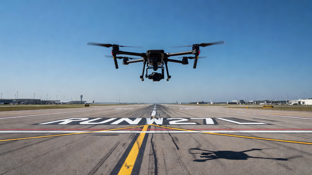
Automated drone inspection uses pre-programmed flight paths, computer vision, and AI analysis to survey infrastructure assets including runways, bridges, roads, and buildings with minimal human piloting. This technology produces consistent, repeatable data for Pavement Condition Index computation, defect detection, and change monitoring across civil aviation and transportation infrastructure.
Automated drone-based infrastructure inspection is a technology process in which an unmanned aerial vehicle (UAV) executes a pre-programmed flight mission — defined by waypoints, grid patterns, corridor routes, or 3D model-guided paths — to capture imagery and sensor data of infrastructure assets with minimal human intervention during the data acquisition phase. The system replaces the traditional model of a remote pilot manually controlling every flight movement with a mission plan that the drone executes autonomously, following precisely defined parameters for altitude, speed, heading, camera trigger interval, gimbal orientation, and overlap percentage.
The system architecture comprises eight core components integrated into a seamless inspection workflow:
UAV Platform — The airframe, propulsion system, flight controller, and avionics that provide the physical flight capability. Platforms range from small multirotors (DJI Mavic 3 Enterprise, Skydio X10) weighing under 4 kg for pavement inspection to larger systems (DJI Matrice 350 RTX, Freefly Astro) capable of carrying multiple payloads for comprehensive infrastructure surveys. Key specifications include maximum takeoff weight (MTOW), flight endurance (typically 25-45 minutes with payload), IP rating for environmental tolerance, and redundancy in critical systems such as GNSS receivers, IMUs, and propulsion.
Mission Planning Software — The ground-based application where operators define the inspection mission before flight. Leading platforms include UgCS, DJI Pilot 2, Pix4Dcapture, DroneDeploy, and Skydio Cloud. These tools allow operators to draw survey areas on a map, specify overlap percentages, set altitude and speed, define gimbal angles, and configure camera parameters. Advanced mission planners support terrain following using a digital elevation model (DEM) to maintain constant ground sample distance (GSD) over variable terrain, 3D model-based planning for complex structures like bridges and buildings, and multi-flight orchestration for large area coverage.
Sensor Payloads — The mission-specific data collection instruments mounted on the drone. Payload selection directly determines which defect types can be detected. RGB cameras are the standard for visual crack detection and orthomosaic generation. Thermal cameras detect subsurface moisture, delamination, and insulation defects. LiDAR scanners generate high-precision point clouds for deformation analysis and vegetation-penetrating surveys. Multispectral sensors enable material classification and vegetation health assessment. Payload mass, power consumption, data rate, and physical dimensions must be compatible with the UAV platform’s payload capacity and mounting provisions.
Obstacle Detection and Avoidance (ODA) — The onboard sensor and processing system that prevents the drone from colliding with obstacles during automated flight. Modern systems use stereoscopic cameras, time-of-flight sensors, LiDAR, or millimeter-wave radar to detect obstacles in the flight path. The avoidance algorithm either replans the route around the obstacle (path replanning) or pauses the mission until the obstacle is cleared. ODA is critical for low-altitude inspection of complex structures where cranes, power lines, vegetation, and structural elements may not be present in the pre-loaded map data.
Command and Control (C2) Data Link — The communication channel between the ground control station and the UAV for transmitting telemetry, flight commands, and payload data. For automated inspection missions, the C2 link must provide sufficient bandwidth for real-time video streaming, position updates at 5-10 Hz, and command transmission with latency under 100 milliseconds. For BVLOS operations, the C2 link typically uses 4G/5G cellular networks or Ku-band satellite links with automatic handover between ground-based relay stations. Redundant C2 links with automatic failover are required for operations beyond visual line of sight per ICAO Doc 10019.
Automated Data Transfer System — The mechanism for transferring captured inspection data from the drone to processing infrastructure. Methods include direct WiFi or USB-C transfer upon landing, cellular upload during flight for smaller data sets, and automated docking stations that offload data and recharge batteries without human intervention. Techno Sky’s DVI2AM docking station, operational at Italian airports since 2022, demonstrates fully automated data transfer where the drone lands on the station, precision-docks using RTK-guided landing, transfers data via high-speed local network, and automatically recharges for the next mission.
Georeferencing and Positioning — The system that ensures every image and data point is tied to a known geographic coordinate. Real-Time Kinematic (RTK) GNSS provides 2-5 cm positional accuracy by receiving real-time corrections from a base station. Post-Processed Kinematic (PPK) achieves similar accuracy without requiring a live data link by recording raw GNSS observations for post-flight correction. Ground Control Points (GCPs) — physically surveyed markers with known coordinates — provide absolute accuracy anchoring. For infrastructure inspection requiring 1-3 cm accuracy, RTK or PPK positioning combined with at least 5-8 GCPs per project is standard practice.
Analysis Pipeline — The software system that converts raw imagery and sensor data into actionable inspection results. This typically includes photogrammetry processing (orthomosaic and point cloud generation via Structure from Motion), computer vision algorithms for defect detection and classification (deep learning models trained on thousands of labeled defect images), measurement tools for crack width, area, and volume computation, and reporting modules that generate condition indices (PCI per ASTM D5340), distress maps, and change detection reports.
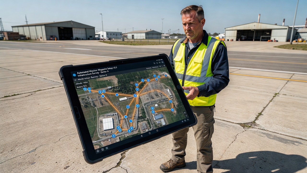
Automated flight planning is the process of defining a drone’s complete mission profile before takeoff, encoding the flight path, data capture parameters, and contingency procedures into a mission file that the flight controller executes autonomously. This eliminates the variability introduced by manual piloting — inconsistent camera angles, varying altitude, uneven speed, and missed coverage areas — and ensures that every survey produces data of consistent quality and coverage.
Waypoint-based flight planning defines a sequence of geographic coordinates (latitude, longitude, altitude) that the drone navigates to in order. At each waypoint, the mission script can trigger specific actions: capture an image, adjust gimbal angle, change speed, or initiate a sensor recording. Waypoint planning is the most flexible method, suitable for complex inspection routes that follow irregular asset geometry.
Modern waypoint planning supports up to 500-1000 waypoints per mission on commercial platforms. Each waypoint can be assigned a specific gimbal pitch angle (from -90° nadir to +45° upward), allowing the drone to capture vertical surfaces such as bridge piers, building facades, and retaining walls. Waypoint planning is used for bridge inspection where the drone must fly a path that follows the bridge deck, descends to inspect girder bearings, and ascends to capture the underside of the deck — a flight path that cannot be described by a simple grid or corridor pattern.
Grid planning creates a serpentine or lawnmower pattern over a defined polygonal area, with parallel flight lines spaced to achieve the specified side overlap between adjacent images. Grid planning is the standard method for area surveys of pavements, runways, taxiways, apron areas, and large building roofs.
Key parameters in grid planning include:
For a standard 3,000 m runway (45 m width), a grid survey at 50 m altitude with 80% forward overlap and 70% side overlap requires approximately 450-600 images. At 1 cm/pixel GSD, this produces an orthomosaic of approximately 300 million pixels covering the full runway extent.
Corridor planning defines a flight path along a linear asset — runway centerline, pipeline route, power line corridor, or roadway segment. The drone follows the corridor centerline while maintaining specified lateral offset and altitude parameters for consistent data capture along the asset length.
Corridor planning is essential for linear infrastructure inspection because grid planning over the full bounding rectangle would be inefficient. For a runway, the corridor follows the runway centerline at a defined altitude, with images captured at intervals determined by the overlap requirement. The corridor width is set to cover the full runway width plus safety margins. For a 45 m wide runway, a corridor width of 60 m ensures complete coverage including shoulders.
Advanced corridor planning supports curved paths following the asset geometry, variable altitude based on terrain profile, and dual-direction passes for stereoscopic coverage. The drone automatically adjusts heading to maintain alignment with the corridor direction, ensuring consistent sun angle and shadow orientation across the survey.
3D model-based planning uses a pre-existing digital surface model (DSM), building information model (BIM), or point cloud of the asset to generate a flight path that maintains constant standoff distance from the structure surface. This is the most advanced form of automated flight planning and is essential for inspecting complex 3D structures such as bridges, stadiums, industrial plants, and transmission towers.
The flight planning algorithm computes a surface offset surface at the specified standoff distance (typically 5-15 m for detailed inspection) and generates a path that covers the structure surface with specified overlap. The drone maintains constant distance to the surface regardless of whether the surface is vertical, horizontal, or curved. For a bridge, this means the drone flies a path that follows the deck surface, the pier faces, the girder bottom flanges, and the abutment walls — all in a single automated mission.
3D model-based planning has been demonstrated in research by Huang et al. (2023) for building exterior inspection, where BIM models were used to generate inspection paths that achieve high coverage rates (over 95%) with occlusion avoidance and collision-free operation. The method is increasingly adopted for bridge inspection, where the complex geometry of truss structures, cable stays, and bearing assemblies makes manual flight planning impractical.
Obstacle detection and avoidance (ODA) is the system capability that enables a drone to detect obstacles in its flight path and autonomously take evasive action without pilot intervention. For automated inspection missions — particularly those flown at low altitude near complex infrastructure — ODA is an essential safety function.
Modern ODA systems employ multiple complementary sensor modalities:
Stereoscopic vision uses two or more forward-facing cameras to compute depth maps through triangulation, similar to human stereo vision. Depth is computed for every pixel in the overlapping camera field of view, providing dense obstacle information at ranges of 0.5-20 m. Skydio’s Autonomy engine uses six 4K navigation cameras arranged in a spherical array to provide 360° obstacle detection coverage. The system processes 240+ million depth measurements per second on an onboard NVIDIA Jetson TX2 platform, enabling real-time obstacle detection at flight speeds up to 15 m/s.
Time-of-flight (ToF) sensors emit infrared light pulses and measure the time required for the reflection to return, providing direct range measurements. ToF sensors are effective at short range (0.1-10 m) and work in low-light conditions where vision-based systems degrade. They are commonly used for downward-facing obstacle detection during landing and for precision docking in automated charging stations.
LiDAR provides active 3D scanning of the environment by emitting laser pulses and measuring return times. LiDAR-based ODA operates at ranges of 50-200 m depending on the sensor power and target reflectivity. It is effective in darkness, fog, and rain — conditions where vision-based systems fail. The Ouster OS0-128, a 128-channel LiDAR commonly integrated on industrial drones, provides 90° vertical field of view and 360° horizontal coverage, generating 2.6 million points per second. LiDAR ODA is particularly valuable for BVLOS operations where the drone must detect and avoid other aircraft (manned and unmanned) during extended missions beyond visual range.
Millimeter-wave radar uses radio waves at 77-79 GHz to detect obstacles at ranges up to 300 m, penetrating fog, rain, dust, and smoke more effectively than optical sensors. Radar ODA provides range and velocity information but limited angular resolution, making it suitable for detecting large obstacles and aircraft traffic rather than small obstacles like power lines.
ODA systems implement several avoidance strategies depending on the operational mode and obstacle type:
Stop and wait — The drone pauses its forward motion when an obstacle is detected and waits for the obstacle to clear or for operator intervention. This is the safest strategy and is the default mode for most commercial drones.
Path replanning — The drone computes an alternative path around the detected obstacle while maintaining the overall mission objectives. Path replanning algorithms use rapidly-exploring random trees (RRT), A* search, or potential field methods to find collision-free paths. This strategy is essential for automated inspection in cluttered environments where stopping at every obstacle would make the mission impractical.
Climb and continue — The drone increases altitude to clear the obstacle and then resumes the planned flight path. This strategy works for obstacles of limited height such as vehicles, equipment, and small structures on the inspection site.
Return to last safe waypoint — If no safe alternative path is found, the drone returns to the last waypoint where it had a clear flight path and pauses for operator instructions. This is the fail-safe behavior when ODA encounters an obstacle that cannot be safely avoided through any available strategy.
ICAO Doc 10019 (Manual on Remotely Piloted Aircraft Systems) specifies detect and avoid (DAA) requirements for RPAS operations, stating that the DAA system must provide the remote pilot with the capability to detect conflicting traffic and other hazards and to maneuver the RPA to avoid collisions. For automated inspection drones operating BVLOS, the DAA system must demonstrate an equivalent level of safety to manned aircraft see-and-avoid requirements (14 CFR 91.113 and ICAO Annex 2, Rule 14).
The FAA’s proposed Part 108 rule (Notice of Proposed Rulemaking, 2024) includes specific requirements for automated drones operating BVLOS, mandating that the aircraft must be equipped with a DAA system capable of detecting and avoiding manned aircraft, obstacles, and other UAS. The system must provide at least the level of safety provided by the visual see-and-avoid requirements in Part 91.113, evaluated through the FAA’s Safety Risk Management process per FAA Order 8040.4.
Beyond Visual Line of Sight (BVLOS) refers to drone operations where the aircraft operates beyond the visual range of the remote pilot or visual observer. BVLOS is the enabling regulatory framework for automated infrastructure inspection at scale, because it allows a single operator to survey assets extending thousands of meters — full runway lengths, miles of pipeline, or expansive bridge networks — without repositioning the pilot or visual observers along the asset.

In the United States, FAA Part 107 currently requires visual line of sight (VLOS) operations for commercial small UAS. BVLOS operations require waivers under 14 CFR 107.200, which the operator must obtain by demonstrating an equivalent level of safety through alternative means of compliance. As of 2024, the FAA had issued fewer than 600 BVLOS waivers nationally, with approval rates increasing as DAA technology matures.
The FAA’s Part 108 NPRM (February 2024) proposes to establish a new regulatory framework specifically for BVLOS operations. Proposed requirements include: (1) the UAS must be designed to FAA-recommended reliability standards for the intended operational environment; (2) the UAS must have a means of compliance for DAA that meets or exceeds the safety of 14 CFR 91.113; (3) operators must complete additional training beyond Part 107 remote pilot certification; (4) operations are limited to 400 ft AGL and airspace classes G and E (with additional authorization for controlled airspace); and (5) the aircraft must be equipped with Remote ID transmitting on both broadcast and network-based protocols.
In Europe, EASA regulations under Commission Implementing Regulation (EU) 2019/947 establish three operational categories for UAS operations. BVLOS operations fall under the Specific category, requiring an operational authorization from the national aviation authority (e.g., ENAC in Italy, DGAC in France, CAA in the UK). The operator must submit a Specific Operations Risk Assessment (SORA) per JARUS guidelines, which evaluates the operational risks and determines the required mitigations. Techno Sky achieved ENAC authorization for BVLOS ILS inspection at Italian airports in 2021, becoming the first UAV operator authorized for BVLOS operations within airport environments in Europe.
Successful BVLOS operations require robust technical systems beyond standard VLOS operations:
Reliable C2 data link with sufficient range to maintain control throughout the mission. For airport runway inspection covering 3,000 m, the C2 link must provide coverage along the full runway length. Cellular 4G/5G networks are increasingly used for BVLOS C2 links, offering range limited only by network coverage. Frequency-hopping spread spectrum (FHSS) in the 2.4 GHz and 5.8 GHz ISM bands provides range of 5-15 km with adequate antenna height and line of sight. For operations beyond cellular coverage, Ku-band satellite links provide global coverage at higher latency (250-600 ms).
Remote ID transmitting the drone’s identity, position, altitude, velocity, and control station location. Remote ID enables air traffic management and manned aircraft awareness of drone operations. The FAA requires Remote ID under 14 CFR 89 for all operations, with broadcast-based Remote ID in the 915 MHz band and network-based transmission via Bluetooth or WiFi.
Flight Termination System (FTS) that can bring the drone to a controlled landing or parachute descent in the event of a critical system failure. For BVLOS operations over populated areas or critical infrastructure, the FTS must be demonstrated to reliably terminate flight within a defined safety area. Techno Sky’s DVI2AM drone incorporates an EASA-compliant FTS with ballistic parachute capable of full-system safe descent from operational altitude.
Automatic dependent surveillance-broadcast (ADS-B) IN capability to receive transmissions from manned aircraft in the vicinity, providing situational awareness that complements the DAA system. The drone must be equipped with an ADS-B receiver that can decode 1090 MHz Extended Squitter transmissions and alert the operator of converging traffic.
The sensor payload carried by the inspection drone determines which defect types can be detected, the measurement accuracy achievable, and the data products that can be generated. Different infrastructure inspection scenarios require different sensor combinations.
RGB (visual spectrum) cameras capture color imagery with red, green, and blue channels, producing images that correspond to human visual perception. High-resolution RGB cameras are the primary sensor for pavement inspection, crack detection, surface distress mapping, and orthomosaic generation.
Modern drone-payload RGB cameras offer 20-61 megapixel resolution with global shutter mechanisms that eliminate rolling shutter distortion — critical for consistent photogrammetric reconstruction. Sony’s full-frame 61 MP sensor (used in Phase One iXM-60 and Hasselblad H6D-100c payloads) provides exceptional image quality at 1 cm or finer GSD from standard inspection altitudes.
For runway pavement inspection, RGB cameras must resolve cracks as narrow as 0.3 mm. At 30 m altitude with a 24 mm focal length lens and 3.76 µm pixel pitch, the GSD is 4.7 mm/pixel, which is insufficient for sub-millimeter crack detection. To achieve 1 mm/pixel GSD, the drone must fly at 15 m altitude or use a longer focal length lens — both of which reduce the area covered per image and increase flight time. The industry standard for runway PCI surveys is 1-3 mm/pixel GSD, requiring careful balance between coverage efficiency and crack detection capability.
Thermal infrared cameras detect long-wave infrared radiation (8-14 µm wavelength) emitted by all objects above absolute zero. Thermal imaging reveals temperature differences on the inspected surface that indicate subsurface conditions invisible to RGB cameras.
Thermal inspection detects: moisture intrusion where evaporative cooling creates cold spots on damp surfaces; delamination where trapped air pockets create thermal barriers producing warm spots during solar heating and cold spots during nighttime cooling; subsurface voids where air gaps create insulation effects visible as temperature anomalies; and spalling where concrete detachment creates thermal bridges between intact and separated layers.
FLIR’s Tau 2 and DJI’s Zenmuse H20T are common thermal payloads for drone inspection, offering 640 × 512 pixel resolution with thermal sensitivity of 0.05°C (Noise Equivalent Temperature Difference, NETD). For pavement inspection, thermal surveys are conducted during the solar heating cycle (10:00-14:00 local time) when solar irradiation creates the maximum temperature differential between sound and delaminated pavement. Research by the Federal Highway Administration (FHWA-HIF-19-002) found that thermal drone surveys detected delaminated bridge deck areas with 85-90% accuracy compared to chain-drag and hammer-sound ground truth surveys.
Light Detection and Ranging (LiDAR) sensors emit laser pulses and measure the time required for each pulse to reflect from surfaces and return to the sensor, producing direct 3D distance measurements. LiDAR generates point clouds with typical point densities of 100-500 points per square meter from drone altitudes of 50-100 m, with vertical accuracy of 1-3 cm for survey-grade sensors.
LiDAR provides three key capabilities not available from photogrammetry alone: vegetation penetration where LiDAR pulses pass through gaps in foliage to measure ground surface elevation; direct 3D measurement without requiring image texture or ambient light; and intensity return data where the reflected pulse strength indicates surface material properties.
For infrastructure inspection, LiDAR is used for: bridge deflection measurement under static load (accuracy 2-5 mm with ground-based LiDAR); power line sag measurement and clearance verification; terrain mapping for drainage analysis and volume calculation; and as-built verification against design models. The Riegl VUX-1LR, a popular drone LiDAR sensor, achieves 100 m range with 10 mm precision at 50 m and 400 kHz pulse repetition rate, producing point clouds with up to 100 points per square meter from 50 m altitude.
Multispectral sensors capture imagery in multiple narrow wavelength bands beyond the visible spectrum, typically including red edge (710-730 nm), near-infrared (840-860 nm), and sometimes multiple bands in the visible spectrum. Multispectral data enables material classification through spectral signature analysis, where different materials (asphalt, concrete, vegetation, water, metal) reflect different proportions of incident radiation at each wavelength.
For pavement inspection, multispectral sensors can distinguish between asphalt and concrete surfaces, identify areas of oil or fuel contamination (which appear as absorption features in the SWIR bands), detect vegetation encroachment at pavement edges, and assess moisture content through the near-infrared water absorption bands. The Micasense RedEdge-P provides five spectral bands (blue, green, red, red edge, near-infrared) at 1.2 MP resolution per band, with downwelling light sensor (DLS) for calibration of ambient lighting conditions.
Data consistency across repeated surveys is the defining advantage of automated drone inspection over manual methods. When a drone follows the same programmed flight path with identical parameters on every visit, the resulting data sets can be directly compared for change detection without the confounding effects of variable capture conditions.
The following parameters must be controlled within defined tolerances to ensure data consistency:
| Parameter | Target Value | Tolerance | Effect of Deviation |
|---|---|---|---|
| Flight altitude (AGL) | 50 m | ±1 m | GSD changes by ±2%; measurement calibration error |
| Ground speed | 5 m/s | ±0.5 m/s | Motion blur variation; image overlap inconsistency |
| Forward overlap | 80% | ±2% | Point matching failure if too low; waste if too high |
| Side overlap | 70% | ±3% | Stripe matching failure; DSM gaps |
| Gimbal pitch angle | -90° (nadir) | ±1° | Georeferencing offset; orthomosaic seam mismatch |
| Sun angle | >30° solar elevation | ±5° | Shadow length variation; crack detection false positives |
| Camera exposure | Manual fixed | Same ISO/shutter/aperture | Color balance shift; feature matching degradation |
Automated inspection relies on consistent georeferencing across surveys. RTK GNSS positioning provides the drone camera position at each image capture point with 2-5 cm accuracy. This position, combined with the camera orientation (gimbal angles), defines the camera exterior orientation parameters that anchor each image in geographic space.
For change detection analysis, repeated surveys must be co-registered to the same coordinate reference system. The co-registration process uses invariant features (pavement markings, runway lights, fixed structures) to compute a transformation that aligns the orthomosaic from survey N to the orthomosaic from survey 1. Residual alignment error after co-registration should be less than 2 pixels — equivalent to 2-6 mm at typical GSD values.
TarmacView’s platform validates input data against defined quality criteria before accepting it into the analysis pipeline. If flight altitude deviates beyond tolerance, or overlap falls below the minimum threshold, the system flags the survey for data quality review. This gatekeeping ensures that only consistent, analysis-grade data enters the condition assessment workflow.
Consistent lighting conditions reduce false positives in automated defect detection. Pavement cracks create different visual signatures under different sun angles: a 1 mm crack is clearly visible at low sun angle (10-20°) where it casts a detectable shadow, but nearly invisible at high sun angle (60-90°) where the crack interior is directly illuminated.
Standard practice for repeat pavement surveys specifies that flights should be conducted within ±1 hour of the same solar time on each visit, with cloud cover not exceeding 30% and no standing water on the pavement surface. The solar elevation angle should exceed 30° to ensure adequate illumination while maintaining sufficient shadow contrast for crack detection algorithms. TarmacView’s mission planning module automatically computes optimal flight windows based on the survey location and date, accounting for local solar ephemeris.
The automation of data transfer and processing completes the end-to-end inspection workflow, turning raw imagery into actionable reports without manual intervention between flight and analysis.
Direct cable transfer is the simplest method: the operator connects the drone to a computer via USB-C or Ethernet after landing and manually initiates data download. For a 300-image runway survey at 20 MP (approximately 6 GB of data), transfer via USB 3.0 takes 2-5 minutes. This method is reliable but requires human presence and manual action, limiting the degree of automation.
Docking station transfer enables fully automated data offloading. When the drone lands on the docking station, a high-speed data connection (USB 3.0 or Gigabit Ethernet) automatically initiates data transfer while the station simultaneously begins battery charging. The DJI Dock 2 and Techno Sky’s DVI2AM stations both support this function. Data is transferred to a local server or cloud storage within 10-15 minutes for a complete survey. The station can prepare the drone for the next mission — recharged batteries, verified sensor calibration, and updated flight plan — without any human interaction.
Cellular transfer during flight streams data to cloud processing during the mission itself, using 4G/5G modems integrated into the drone. This enables near-real-time processing where orthomosaic generation begins before the drone has landed. For large data sets (6+ GB per survey), cellular transfer extends the data delivery time compared to docking station transfer (30-60 minutes), but provides the advantage of enabling rapid turnaround for time-critical inspections.
The automated processing pipeline converts raw imagery into inspection deliverables through several stages:
Photogrammetric reconstruction uses Structure from Motion algorithms to align images, compute camera positions, generate dense point clouds, and produce orthomosaics and DSMs. Processing a 300-image runway survey at 1 cm GSD requires approximately 2-4 hours on a GPU-accelerated workstation (NVIDIA RTX 4090 or equivalent). Cloud-based processing services (Pix4Dmatic, Agisoft Metashape cloud) reduce this to 30-60 minutes using distributed computing across multiple GPU nodes.
Quality assurance validates the reconstruction against defined criteria: GSD within tolerance of the flight plan target; check point RMSE below 2 cm horizontal and 3 cm vertical; orthomosaic seam continuity without visible blending artifacts or color mismatches; point cloud density sufficient for defect detection at the required minimum feature size.
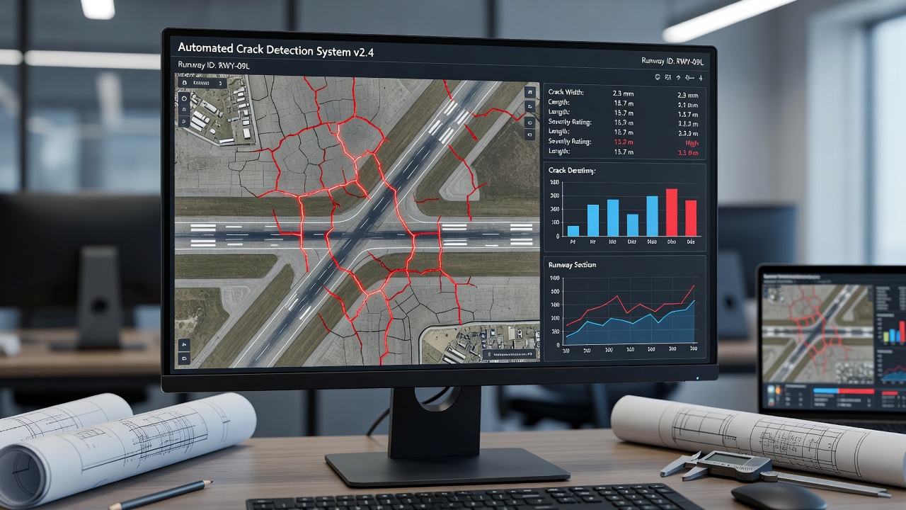
Defect detection and classification applies computer vision algorithms and deep learning models to identify, classify, and measure surface defects on the orthomosaic. The deep learning model — typically a U-Net, DeepLabV3+, or Mask R-CNN architecture trained on 10,000+ labeled infrastructure defect images — performs pixel-level semantic segmentation that classifies each pixel as intact surface, crack (longitudinal, transverse, alligator, block), spall, patching, raveling, or joint distress. Crack width is measured to 0.2 mm precision using sub-pixel edge detection.
Condition index computation calculates aggregate pavement condition metrics per the ASTM D5340 PCI methodology. The pavement is divided into sampling units (typically 20 contiguous slabs for jointed concrete pavement, or 500 m² sections for asphalt pavement). Within each sampling unit, the density of each distress type at each severity level is computed, deduct values are determined from ASTM tables, and the PCI is calculated on a 0-100 scale.
TarmacView’s inspection platform provides the analysis and reporting engine that consumes automated drone survey data and produces condition assessments aligned with aviation industry standards.
TarmacView accepts orthomosaics, point clouds, and DSM data generated from automated drone surveys. Input requirements include: orthomosaic GSD of 1-3 mm/pixel for runway PCI analysis, with higher GSD (1 mm or better) required for crack width measurement below 0.5 mm. The orthomosaic must be georeferenced in a known coordinate reference system (WGS84 UTM or the local CRS) with check point validation. Image overlap must be verified to meet the minimum thresholds required for photogrammetric reconstruction (80% forward, 70% side). The data must be delivered with complete EXIF metadata including GNSS position, altitude, gimbal orientation, camera calibration parameters, and capture timestamp for every image.
When a survey data set is uploaded to TarmacView, the platform executes a structured analysis workflow:
Data ingestion — The orthomosaic and point cloud are loaded into the spatial database. Metadata fields (survey date, flight parameters, drone model, camera model, GSD, CRS) are extracted and validated against the project requirements.
Pavement segmentation — The pavement area is automatically extracted from the orthomosaic using deep learning segmentation models trained on airfield imagery. Runway markings, shoulders, blast pads, and adjacent taxiways are identified and separated from the analysis pavement.
Sampling unit delineation — The pavement is divided into PCI sampling units per ASTM D5340. For jointed concrete airfield pavement, units are defined as 20 consecutive slabs (±1 slab) per ASTM D5340-19 Section 8.3.1. For asphalt pavement, units are approximately 500 m². The sampling unit boundaries are stored as spatial polygons in the GIS data model.
Automated distress detection — The computer vision pipeline processes each sampling unit, detecting and classifying all standard PCI distress types: crack types (longitudinal, transverse, diagonal, alligator, block), spalling, patching, joint spalling, corner break, shattered slab, blow-up, pumping, faulting, settlement, raveling, weathering, bleeding, rutting, corrugation, depression, swelling, and polished aggregate. Each distress instance is stored as a georeferenced vector polygon with attributes for distress type, severity (Low, Medium, High per ASTM criteria), measured dimensions (length, width, area), and the probability score from the detection model.
PCI computation — For each sampling unit, distress densities are computed, deduct values are applied from ASTM D5340 deduct value curves, and the corrected deduct value (CDV) is extracted through iterative adjustment. The final PCI for each unit is calculated as 100 minus the CDV.
Report generation — TarmacView produces a comprehensive inspection report including: overall PCI for the runway and individual sampling unit PCIs; distress maps overlaid on the orthomosaic with color-coded severity; crack measurement tables with length, width, and classification for each detected crack; statistical distribution of distress types across the pavement; and trend analysis comparing current PCI against historical surveys.
Automated drone inspection operations are governed by a layered regulatory framework spanning international standards, national regulations, and local airspace restrictions.
ICAO Annex 6, Part IV — International Standards and Recommended Practices for Remotely Piloted Aircraft Systems (RPAS), effective November 2026, establishes the international framework for RPAS operations including inspection drones. The annex covers airworthiness certification (RPAS must meet type certification standards appropriate to their category), operator certification (operators must hold an RPAS operator certificate), remote pilot licensing (pilots must hold a Remote Pilot Licence), and operational rules for automated and beyond-visual-line-of-sight flight.
ICAO Annex 14, Volume I — Aerodrome Design and Operations, governs the physical characteristics of aerodromes including pavement surface condition requirements. The annex specifies that runway surface condition must be monitored and maintained within defined limits, with particular attention to friction characteristics, surface irregularities, and contaminant accumulation. Automated drone inspection provides the consistent, measurable data required for Annex 14 compliance verification. The aerodrome height restrictions for drone operations are addressed in Annex 14 Section 4.2 (Obstacle Limitation Surfaces) and the Manual on Remotely Piloted Aircraft Systems (Doc 10019).
ICAO Doc 8071 — Manual on Testing of Radio Navigation Aids, Volume 3 (Testing of Satellite-Based Radio Navigation Systems), references UAV-based inspection of instrument landing systems and other navaids. Techno Sky’s automated UAV ILS inspection solution, approved by ENAC in 2021, demonstrates compliance with Doc 8071 measurement requirements for localizer course alignment, glide path angle, and displacement sensitivity.
14 CFR Part 107 — Small Unmanned Aircraft Systems, governs commercial UAS operations under 25 kg (55 lbs). Key requirements for automated inspection: remote pilot certification (Part 107 Remote Pilot Certificate), aircraft registration, VLOS operations (or BVLOS waiver under 107.200), daylight operations (or night waiver under 107.29), maximum altitude of 400 ft AGL, maximum ground speed of 100 mph (87 knots), and Remote ID compliance (14 CFR Part 89).
Part 107 waivers have been granted for automated inspection operations when operators demonstrate equivalent safety. As of 2024, the FAA has granted over 1,200 BVLOS waivers nationally, with 65% approved for operations in controlled airspace with coordination with air traffic control.
14 CFR Part 108 (proposed, 2024) — Will establish a new regulatory framework specifically for BVLOS drone operations. The proposed rule includes requirements for: aircraft design and production standards; reliability analysis and continued airworthiness; DAA system performance standards; operator certification with enhanced training; operational authorizations without individual waiver petitions; and standardized BVLOS operational volumes.
FAA Advisory Circular 107-2 — Small Unmanned Aircraft Systems, provides guidance for Part 107 compliance. AC 107-2A specifically addresses inspection operations, noting that automated flight planning and execution is permitted under Part 107 as long as the remote pilot maintains the ability to override the automation and manually control the aircraft.
Commission Implementing Regulation (EU) 2019/947 — Rules and procedures for the operation of unmanned aircraft, establishes three operational categories:
| Category | Risk Level | Requirements | Relevance to Inspection |
|---|---|---|---|
| Open (A1, A2, A3) | Low | No operational authorization needed; CE class marking; drone registration | Small inspection drones (< 250 g or < 4 kg in A2) |
| Specific (STS-01, STS-02) | Medium | Operational authorization from CAA; SORA risk assessment; PDRA declaration | Standard inspection operations including BVLOS with mitigations |
| Certified | High | Type certification; operator certificate; licensed remote pilot | Large inspection drones (> 25 kg); operations over populated areas |
The Specific category applies to most automated inspection operations, particularly BVLOS and flights over critical infrastructure. The operator must submit a Specific Operations Risk Assessment (SORA) per JARUS guidelines, which evaluates ground risk and air risk classes to determine the required safety mitigations. Techno Sky’s ENAC authorization for BVLOS ILS inspection at Italian airports falls under the Specific category with a SORA demonstrating that automated flight, redundant C2 links, and FTS reduce operational risk to acceptable levels.
EASA Light UAS Operator Certificate (LUC) — Operators meeting specific competency requirements can self-authorize operations within privileges granted by their LUC. Techno Sky holds an EASA LUC that authorizes automated BVLOS inspection operations at Italian airports, demonstrating that the operator’s safety management system, training program, and operational procedures meet EASA standards for self-regulation.
Remote ID is the capability of a drone in flight to broadcast identification, position, altitude, velocity, and control station location. Remote ID enables airspace regulators, manned aircraft pilots, and law enforcement to identify and track drones during flight.
In the United States, 14 CFR Part 89 — Remote Identification of Unmanned Aircraft, required Remote ID compliance by September 16, 2023. Drones manufactured after that date must have built-in Remote ID broadcast capability, transmitting on WiFi or Bluetooth at 1 Hz update rate with position accuracy of 10 m. Automated inspection drones operating BVLOS must transmit Remote ID via both broadcast and network (internet) methods.
In Europe, Delegated Regulation (EU) 2019/945 requires Remote ID for all drones in the Specific category and for open category drones with a class marking. The standard requires broadcast of the operator registration number, the UAS serial number, the geographical position of the UAS and the remote pilot station, and the time mark.
The ability to conduct repeatable automated surveys and detect changes over time is one of the most powerful capabilities enabled by automated drone inspection. Consistent flight parameters, georeferencing, and data processing ensure that differences between successive surveys reflect actual asset changes rather than measurement variability.
Change detection between successive surveys follows a structured methodology:
Co-registration aligns the survey N orthomosaic and point cloud to the survey 1 baseline using invariant reference features. A transformation matrix (typically a rigid-body or affine transformation with 6-7 parameters) is computed from automatically matched tie points on pavement markings, runway lights, and fixed structures. Residual error after co-registration should be less than 2 pixels. Co-registration accounts for small variations in flight path and GNSS positioning that cannot be eliminated through automation alone.
Pixel-level differencing computes the difference in pixel values between the reference and repeat orthomosaic for each pixel location. The difference image highlights areas of change (new cracks, patching, staining, rubber buildup) as regions with statistically significant pixel value deviation. The threshold for significant change is set at 3 standard deviations of the per-pixel difference distribution, corresponding to a 99.7% confidence level that the change is real rather than measurement noise.
Vector-based change detection for specific defect instances compares the crack and distress polygons detected in each survey. A crack detected in survey N that was not present in survey N-1 is classified as new development. A crack that increased in length by more than 5 cm between surveys is classified as propagation. Cracks that decreased in width or disappeared are classified as maintenance interventions (sealed or repaired). Each change instance is recorded with the magnitude of change, the time interval, and the statistical confidence.
The following metrics are computed for each sampling unit between successive surveys:
Delta PCI — The change in Pavement Condition Index (PCI) between surveys, expressed as points per year. A delta PCI of -5 points per year indicates the pavement is deteriorating at 5 PCI points annually. The ASTM D5340 standard defines that a PCI change of more than 10 points between surveys is statistically significant at 95% confidence for properly conducted surveys.
Crack density change — The change in total crack length per unit area (m/m²), expressed as linear meters of cracking per 100 m². Increases in crack density indicate fatigue cracking development, reflective cracking propagation, or thermal crack growth.
Area of new distress — The total area (m²) of pavement that developed new distress (any type) since the previous survey, expressed as a percentage of the sampling unit area. New distress areas greater than 5% of the unit area warrant maintenance intervention under ASTM maintenance prioritization criteria.
Rut depth progression — For asphalt pavement, the change in maximum rut depth within each wheel path zone, derived from DSM or point cloud comparison. Rut depth progression exceeding 3 mm per year in the outer wheel path indicates structural deterioration requiring investigation.
Rubber deposit accumulation — The change in tire rubber coverage within the touchdown zone. Rubber deposits reduce surface friction coefficient by 30-50% at coverage levels above 25%, making this a critical safety parameter. Automated drone surveys quantify rubber coverage through multispectral analysis in the near-infrared band where rubber exhibits distinct absorption characteristics.
The International Civil Aviation Organization’s Aerodrome Design Manual (Doc 9157, Part 3) recommends that pavement condition surveys be conducted at intervals not exceeding: Annual for airfields with high traffic intensity (annual departures exceeding 25,000); Biennial for medium traffic intensity (10,000-25,000 annual departures); and Triennial for low traffic intensity (less than 10,000 annual departures). Automated drone inspection enables these recommended frequencies at substantially lower cost than manual surveys, and the resulting time-series data provides the evidence base for predicting pavement deterioration rates and optimizing maintenance intervention timing.
TarmacView’s platform maintains a historical record of every survey conducted on an airfield pavement, enabling longitudinal trend analysis across multiple years. The system computes deterioration curves for each sampling unit, identifies units with accelerated deterioration (where the delta PCI exceeds the airfield average by more than 2 standard deviations), and generates maintenance prioritization lists sorted by the expected PCI impact of each recommended intervention. This data-driven approach moves pavement management from reactive maintenance (fixing failures when they occur) to predictive maintenance (intervening before failures develop), reducing lifecycle costs by an estimated 30-50% based on FAA and US Air Force pavement management studies.
Automated drone-based infrastructure inspection replaces subjective, variable manual inspection with consistent, repeatable data acquisition and analysis. The system integrates programmed flight planning, obstacle detection and avoidance, multi-sensor payloads, automated data transfer, and AI-powered defect detection into a seamless end-to-end workflow. For runway pavement inspection — the primary application domain — the technology delivers ground sample distances of 1-3 mm, crack width measurements with 0.2 mm precision, Pavement Condition Index computation per ASTM D5340, and statistically validated change detection across multi-year surveys. The regulatory framework for automated inspection operations is evolving rapidly, with the FAA’s proposed Part 108 and EASA’s Specific category operational authorizations enabling BVLOS operations at airports and along infrastructure corridors. As sensor technology advances, processing algorithms improve, and regulatory pathways mature, automated drone inspection will become the standard method for infrastructure condition assessment across aviation, transportation, energy, and industrial sectors.
TarmacView transforms drone-captured runway imagery into actionable condition assessments. Our automated pipeline processes inspection data from flight to final PCI report, enabling consistent, repeatable pavement evaluation across your airfield network.
Drone flight planning for infrastructure inspection involves designing automated flight paths (waypoint missions) with appropriate altitude, speed, overlap, gim...
AI-based crack detection uses computer vision — convolutional neural networks, vision transformers, and semantic segmentation models — to automatically identify...
Drone-based infrared thermography mounts thermal cameras on UAVs to rapidly survey bridge decks and pavements for delamination, debonding, and moisture from the...