What is Azimuthal?
Azimuthal: A Comprehensive Guide to Aviation and Navigation
What Does Azimuthal Mean?
Azimuthal describes anything defined or measured by azimuth, the horizontal angle measured clockwise from a reference direction (usually north) to a target. In aviation, navigation, radar, and satellite tracking, azimuthal directions are indispensable for specifying heading, plotting courses, and aligning equipment. The concept ensures that everyone, from pilots and air traffic controllers to surveyors and satellite engineers, uses a universal language of direction, minimizing errors and maximizing safety.
The Origin and Core Principles of Azimuth
The word azimuth comes from the Arabic al-sumut (السُّموت), meaning “the directions.” Through medieval translations, it entered Western science as a cornerstone in celestial navigation, land surveying, and later aviation.
Core Principle:
Azimuth is the horizontal angle, measured in degrees (0°–360°), clockwise from a reference direction (typically true north) to a target:
- 0°/360° = North
- 90° = East
- 180° = South
- 270° = West
Azimuth is always referenced from a fixed starting point and measured in the horizontal plane.
Table: Azimuth vs. Related Terms
| Term | Definition | Reference Direction | Plane |
|---|---|---|---|
| Azimuth | Angle from fixed north to object, measured clockwise | True/magnetic/grid north | Horizontal |
| Bearing | Direction to object, can be relative or absolute | Variable | Horizontal |
| Heading | Direction nose of aircraft/vessel points | Usually true/magnetic N | Horizontal |
| Course | Intended path over ground | True north | Horizontal |
Reference Directions: True North, Magnetic North, and Grid North
Azimuthal measurements hinge on the reference used for zero degrees:
- True North: Geographic North Pole, stable and used for charting and flight planning.
- Magnetic North: The direction a compass points, changes over time and location due to Earth’s magnetic field variations.
- Grid North: Vertical grid lines on a map projection, crucial for accurate plotting on flat maps.
Declination is the difference between true north and magnetic north. The Grid-Magnetic (G-M) angle is the difference between grid north and magnetic north. These discrepancies are shown in declination diagrams on ICAO-compliant aeronautical charts and must be accounted for when converting between azimuth types.
Key Tip:
Always check which north is referenced for any azimuthal measurement to avoid navigational errors.
Methods and Instruments for Measuring Azimuth
Mechanical Tools
- Magnetic Compass: Measures magnetic azimuth, requires correction for declination.
- Protractor: Used on maps for grid azimuths.
- Gyrocompass: Provides true north by using Earth’s rotation, standard in aircraft and ships.
Electronic and Digital Systems
- Digital Navigation Systems: Calculate azimuth automatically using GPS and onboard sensors.
- Radar Systems: Use azimuthal angles to track aircraft positions from a radar station.
- Satellite Tracking Equipment: Employs azimuth and elevation motors for precise antenna alignment.
Practical Example:
A pilot uses a Flight Management System (FMS) to compute the azimuth to a destination, factoring in the aircraft’s position, magnetic variation, and required heading.
Measuring Azimuth: Step-by-Step
On a Map (Grid Azimuth)
- Mark starting and target points.
- Draw a line between them.
- Align a protractor’s baseline with the map’s north-south grid.
- Read the azimuth at the intersection.
In the Field (Magnetic Azimuth)
- Hold compass level at starting point.
- Sight the target.
- Rotate until the needle aligns with north.
- Read the angle under the index line.
With Modern Navigation Systems
Automated systems combine compass, GPS, and gyroscope data to continuously update the aircraft’s azimuth.
Azimuth in Spherical Coordinates and Aviation
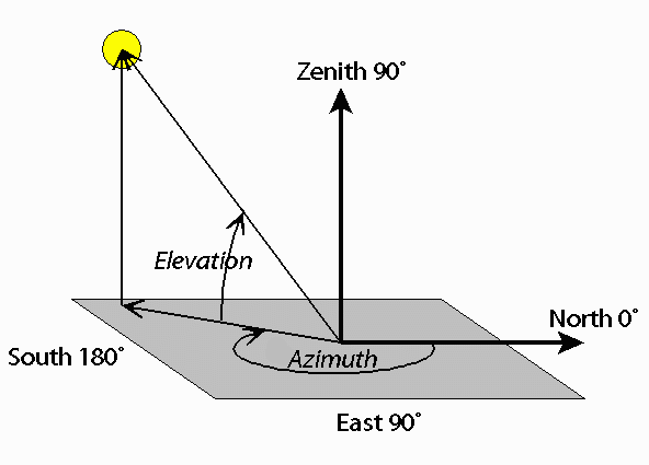
In three-dimensional systems, such as radar or satellite tracking, azimuth is paired with elevation (vertical angle above the horizon).
- Azimuthal Angle: Horizontal direction from north to the target.
- Elevation Angle: Upward angle from the horizontal plane to the target.
Application:
ILS (Instrument Landing System) and radar approach systems provide both azimuth (localizer guidance) and elevation (glideslope) to pilots.
Key Related Terms
- Azimuth Angle: Horizontal angle (often used in spherical coordinates).
- Elevation (Altitude): Vertical angle above the horizon.
- Back Azimuth: Reciprocal direction (add or subtract 180° as appropriate).
Example Table:
| Azimuth | Back Azimuth |
|---|---|
| 075° | 255° |
| 200° | 020° |
Azimuth Conversion: Grid, Magnetic, and True
Conversion Process
- Grid to Magnetic: Subtract G-M angle if magnetic north is east of grid north, add if west.
- Magnetic to Grid: Add G-M if east, subtract if west.
Example:
Grid azimuth = 120°, G-M angle = 8° east → Magnetic azimuth = 112°.
ICAO Standard:
Flight plans must specify the reference. Chart updates are required if magnetic variation changes significantly.
Calculating Azimuth: Aviation Examples
- On a chart: Mark points, draw line, use protractor for grid azimuth.
- With a compass: Sight target, align needle, read angle for magnetic azimuth.
- With FMS: Enter coordinates, system displays true azimuth and computes magnetic heading.
Back Azimuth: Used for reciprocal courses, holding patterns, and missed approaches.
Practical Applications
- Aviation and Navigation: Defining airways, headings, and radar vectors.
- Radar/ATC: Aircraft tracking and traffic separation.
- Satellite/Antenna Alignment: Directional positioning for communication.
- Surveying/Cartography: Mapmaking, boundary definition, and infrastructure layout.
- Approach Navigation: Precision landings using ILS or equivalent systems.
Worked Example: Azimuthal Navigation in Aviation
Scenario:
An aircraft flies from A to B, 120 NM southeast.
- Grid azimuth: 135°
- Local magnetic variation: 7° west
- Magnetic azimuth: 135° – 7° = 128°
- FMS input: Enter 135°, system computes required magnetic heading as 128° (plus wind correction).
- Back azimuth for return: 135° + 180° = 315°
Advanced Considerations: ICAO and Modern Systems
ICAO Standards:
Documents such as Annex 4 and Annex 10 specify chart requirements, conversion formulas, and reference use.
Modern Systems:
- GNSS: Computes azimuths using latitude/longitude and Earth’s curvature.
- Inertial Reference Systems: Use gyroscopes and accelerometers for continuous azimuth tracking.
Summary
Azimuthal concepts are foundational in aviation and navigation, underpinning everything from compass headings and radar vectoring to chart plotting and satellite alignment. Mastery of azimuthal measurement, conversion, and application ensures precise, safe, and efficient operations across the aviation industry and beyond.
Frequently Asked Questions
- What does azimuthal mean in aviation?
- Azimuthal refers to anything measured by azimuth, the horizontal angle from a fixed reference like true north. In aviation, azimuthal data are used for heading alignment, radar vectoring, satellite tracking, and chart-based navigation to ensure safe, accurate courses.
- How is azimuth different from bearing or heading?
- Azimuth is always measured clockwise from a defined north (true, magnetic, or grid) to a target, as a 0–360° angle. Bearing can be relative or absolute and may use different references. Heading is the direction the nose of an aircraft points, not necessarily toward a target.
- How are azimuthal angles measured and used?
- Azimuthal angles are measured with compasses, protractors, gyrocompasses, and digital navigation systems. In aviation, they support flight planning, radar tracking, and aligning navigation aids. Accurate measurement requires careful reference to true, magnetic, or grid north.
- What is the difference between true north, magnetic north, and grid north?
- True north points to the geographic North Pole and is a fixed reference. Magnetic north is where a compass points, which shifts over time. Grid north is the map's vertical grid line, used in projected maps. Correct azimuthal measurement requires knowing which reference is used.
- What is a back azimuth?
- A back azimuth is the direction opposite a given azimuth. To find it, add 180° if the azimuth is ≤180°, or subtract 180° if it’s >180°. This is vital for reciprocal courses and return navigation in aviation and surveying.
- Why is the azimuthal concept important for radar and satellite tracking?
- Radar and satellite systems use azimuthal angles to align antennas or dishes and to track targets in the sky. Azimuthal measurements allow precise positioning and directional communication, which is critical for safe airspace management and reliable satellite links.
This is a reference entry. TarmacView provides drone inspection services and doesn't sell the equipment or materials described in this glossary.