A blowup is a localized upward buckling or shattering of concrete pavement at a transverse joint or crack during hot weather, caused when compressive stresses from thermal expansion exceed the slab’s buckling capacity. This glossary entry covers the failure mechanism, thermal expansion stress analysis, incompressible infiltration factors, safety hazards including FOD generation and vehicle impact, prevention strategies including pressure relief joints and adequate joint width, airport pavement considerations, detection methods, and emergency repair procedures per ICAO and FAA standards.
What is a Blowup in Concrete Pavement?
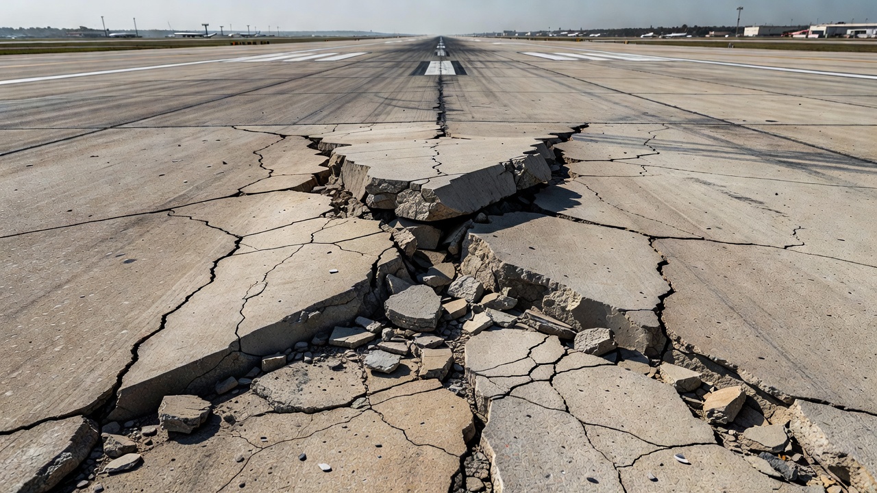
A blowup (also called a pavement blowup, thermal blowup, concrete blowup, or buckling failure) is a severe localized upward displacement, shattering, or crushing of Portland Cement Concrete (PCC) pavement occurring at a transverse joint or crack during hot weather conditions. The phenomenon is classified as a distortion-type distress under ASTM D5340 (Standard Test Method for Airport Pavement Condition Index Surveys) and is one of the most hazardous pavement defects because it develops abruptly, produces large angular fragments of shattered concrete, and creates an immediate Foreign Object Debris (FOD) hazard on airfield movement areas.
The blowup distress develops through a mechanical process: as the concrete slab heats up and expands, it generates compressive stresses within the pavement structure. When the expansion joints — which are designed to accommodate this movement — are unable to function properly due to the presence of incompressible material, inadequate original joint width, overly long joint spacing, or a combination of these factors, the compressive forces accumulate. Once these forces exceed the slab’s critical buckling load, the concrete fails suddenly in compression at the joint or crack, producing the characteristic upward displacement and fragmentation.
The FAA Pavement Surface Evaluation and Rating (PASER) manual (AC 150/5320-17A Appendix B) describes blowups as follows: “Concrete slabs may push up or be crushed at a joint. This is caused by expansion of the concrete where incompressible materials (sand, debris, etc.) have infiltrated into poorly sealed joints. As a result, there is no space to accommodate expansion.” The PASER manual further notes that blowups are more common in older pavements with long joint spacing and in pavements where aggregate is susceptible to alkali-silica reaction (ASR).
Definition and Mechanism
The blowup mechanism involves a sequence of physical events that occur progressively as pavement temperature rises. The concrete slab, which was placed and cured at some reference temperature (the setting temperature or zero-stress temperature), begins to expand as the ambient temperature increases. For every degree Celsius of temperature rise, a concrete slab with a coefficient of thermal expansion (CTE) of 10 × 10⁻⁶ /°C will expand linearly by approximately 0.01 mm per meter of slab length. For a typical 6-meter (20-foot) joint spacing, this translates to approximately 0.06 mm of expansion per degree Celsius.
Key parameters governing the buckling process:
Parameter
Typical Value Range
Effect on Blowup Risk
Coefficient of Thermal Expansion (CTE)
7 – 13 × 10⁻⁶ /°C
Higher CTE → greater expansion → higher risk
Joint Spacing
4.5 – 7.6 m (15 – 25 ft)
Longer spacing → more accumulated expansion → higher risk
Reduces available expansion space → increases risk
The accumulated compressive force per unit width of slab is given by:
F = E × α × ΔT × h
where E is the concrete elastic modulus (typically 28–35 GPa), α is the CTE, ΔT is the temperature increase above the setting temperature, and h is the slab thickness. For a 250 mm (10-inch) thick slab with CTE of 10 × 10⁻⁶ /°C subjected to a 30 °C temperature rise, the accumulated compressive force per meter of slab width is approximately 2.1 MN/m — a force of over 200 metric tons per meter of pavement width.
When this force encounters resistance to horizontal movement — either from incompressible material packed into the joint space or from the adjacent slab — the stress state transitions from one of free expansion to one of constrained compression. The slab then behaves as a beam-column under axial compression. The critical buckling load for a pavement slab resting on a elastic foundation was first rigorously analyzed by Kerr (1984) and later extended by numerous researchers. The critical temperature increase at which buckling occurs is a function of slab geometry, material properties, joint condition, and foundation stiffness.
The Wisconsin Highway Research Program project 0092-24-03 (2025) developed a validated three-dimensional finite element model of pavement buckling in Abaqus, simulating slab-joint-base-subgrade interactions with connector elements for joints and Coulomb friction for the slab-base interface. The research found that joint stiffness had the greatest impact on safe temperature, followed by setting temperature and CTE. Slab-base friction (within expected ranges) and subgrade stiffness had minimal effects. This research resulted in the Pavement Buckling Risk Indicator and Simulation Kit (PB-RISK), an Excel-based tool that assesses buckling risk using both long-term climate projections (CMIP6 models) and short-term (14-day) weather forecasts.
Thermal Expansion and Compressive Stress
The coefficient of thermal expansion (CTE) of Portland cement concrete is a critical material property governing blowup susceptibility. Concrete CTE values typically range from 7 to 13 × 10⁻⁶ /°C (4 to 7 × 10⁻⁶ /°F), depending primarily on the aggregate type used in the mix. Quartzite aggregate produces concrete with the highest CTE (approximately 12–13 × 10⁻⁶ /°C), while limestone aggregate produces lower CTE values (approximately 7–9 × 10⁻⁶ /°C). The FHWA research report “Determination of Coefficient of Thermal Expansion Effects on Jointed Concrete Pavements” (LTRC Project 451, 2011) demonstrated that the CTE of concrete directly influences the maximum joint spacing that can be safely used in jointed plain concrete pavement (JPCP) design.
The temperature differential experienced by the pavement — the difference between the peak pavement temperature at the time of potential blowup and the zero-stress temperature (the temperature at which the concrete slab was effectively locked into the pavement system) — is the primary driver of compressive stress accumulation. The zero-stress temperature is influenced by the ambient temperature at the time of placement and curing, the heat of hydration during curing, and any subsequent early-age thermal cycles. Construction during cold months results in a lower zero-stress temperature, which means a larger thermal differential will accumulate during summer heatwaves. The Wisconsin DOT research recommends minimizing construction during cold months specifically for this reason.
Pavement temperature differs substantially from ambient air temperature. On a clear summer day with an air temperature of 38 °C (100 °F), direct solar radiation can raise the pavement surface temperature to 60–70 °C (140–160 °F). The temperature profile through the slab depth is non-linear — the surface is significantly hotter than the bottom of the slab due to solar heating. This temperature gradient creates differential expansion through the slab depth, causing curling stresses that compound the axial compressive stresses. The combined stress state can trigger buckling at lower average temperatures than would be predicted by uniform temperature analysis alone.
The thermal performance gap (TPG) concept, introduced by Chhay et al. (2021), describes the temperature increase required to trigger pavement growth and blowup. The trigger temperature for pavement growth (TTPG) is affected by the accumulation of slab expansion from alkali-silica reaction (ASR), the amount of incompressible material in joints, and the history of previous thermal cycles. Research published in Construction and Building Materials (2020) established that TTGP is a function of the cumulative joint closure from multiple cycles of expansion and incompressible material intrusion.
Incompressible Infiltration Contributing Factor
The single most controllable contributing factor to concrete pavement blowups is the infiltration of incompressible materials into transverse joints. Joints in concrete pavements are designed to provide a gap — typically 3 to 6 mm (1/8 to 1/4 inch) at contraction joints and 12 to 25 mm (1/2 to 1 inch) at expansion joints — into which the concrete slab can expand during periods of rising temperature. When this joint space becomes filled with incompressible material, the slab’s ability to accommodate thermal expansion is progressively eliminated.
Sources of incompressible joint infiltration include:
Sand and fine aggregate particles tracked onto the pavement surface by vehicular traffic and subsequently worked into joint openings by tire action and water flow
Spalled concrete fragments from joint edges that break loose and fall into the joint space
Broken pavement marking materials (thermoplastic, tape, paint) that abrade and accumulate in joints
Vegetative debris (grass clippings, leaves, seed pods) that packs into joint openings
Failed joint sealant material that has debonded from the joint walls and fallen into or been displaced from the joint
Corrosion products from dowel bars that expand within the joint space
ASR gel that exudes from cracks and joints, swelling when exposed to moisture
The progressive accumulation of incompressible material closes the joint gap incrementally over time. As the gap narrows, less expansion space remains available during each successive thermal cycle. A joint that was originally 6 mm wide and has accumulated 4 mm of incompressible fill has only 2 mm of remaining expansion capacity. Under a 30 °C temperature rise with 6 m joint spacing, the slab expansion demand is approximately 1.8 mm — nearly consuming the entire remaining joint space. Any further temperature increase or additional accumulation will result in physical contact between adjacent slab ends, initiating compressive stress buildup.
The Illinois Division of Highways study (1967) — “A Study of Blowups in Rigid Pavements in Illinois” — was one of the earliest systematic investigations documenting the relationship between joint incompressible infiltration and blowup occurrence. The study found that blowups occurred almost exclusively at joints where the joint space was effectively closed by accumulated debris, even when all other design parameters (joint spacing, slab thickness, concrete quality) met contemporary standards. Further research by Gress (1977) on blowups in resurfaced concrete pavements confirmed that the problem was exacerbated by asphalt overlays, which reduced the thermal gradient through the slab and increased the average slab temperature during hot periods.
Alkali-Silica Reaction (ASR) is a concrete durability problem that contributes to blowup potential through internal expansion of the concrete itself. ASR occurs when reactive silica in certain aggregates reacts with alkalis (Na₂O and K₂O) from the cement in the presence of moisture, producing a hydrophilic gel that absorbs water and expands. The expansion pressure from ASR can cause the concrete slab to grow internally, further closing joint gaps and increasing compressive stress. The FHWA Alkali-Silica Reactivity Field Identification Handbook (HIF-12-022) documents how ASR-induced expansion has caused joints to close between adjacent pavement sections, and reports that incompressible material trapped between sections has caused structural buildup and eventual blowup. Pavements with ASR-affected aggregate experience blowups at lower temperatures and with greater frequency than non-reactive pavements.
Blowup Hazard
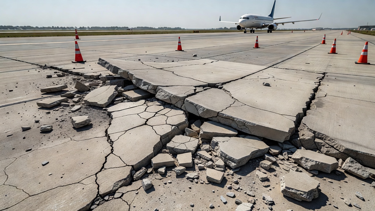
Blowups present immediate and severe safety hazards on any paved surface where vehicles operate, and these hazards are magnified on airfield pavements where aircraft operate at high speeds, with high load concentrations, and with minimal tolerance for surface irregularities.
Vehicle Impact Hazard
The upward displacement of concrete at a blowup — which can range from 25 mm (1 inch) to over 150 mm (6 inches) of vertical elevation change — creates an obstacle that aircraft landing gear and ground support equipment impact at operational speeds. On runways, where aircraft touchdown occurs at speeds of 130–160 knots (240–300 km/h), impact with a 100 mm blowup creates instantaneous vertical accelerations that can:
Puncture aircraft tires as the sharp edges of shattered concrete fragments penetrate the tire tread at impact velocities exceeding 150 m/s
Cause landing gear structural damage through sudden deceleration loads
Induce loss of directional control when the impact occurs asymmetrically across the landing gear
Generate secondary debris as tire fragments and additional pavement pieces are ejected at high velocity
The hazard is equally significant on taxiways, where aircraft may be operating at lower speeds but where the pilot’s ability to detect and avoid the blowup is limited by the forward viewing angle from the cockpit and the distance between the nose gear and the main gear.
Foreign Object Debris (FOD) Generation
The shattered concrete produced by a blowup consists of angular fragments ranging from small mortar particles (2–5 mm) to large chunks exceeding 200 mm (8 inches) in their longest dimension. These fragments become Foreign Object Debris (FOD) on the airfield movement area. The FOD hazard from blowups is particularly dangerous because:
The fragments are numerous — a single blowup event at a transverse joint can produce dozens of concrete fragments scattered across the pavement surface
The fragments are sharp and angular — the brittle fracture of PCC produces fragments with razor-sharp edges that can cut aircraft tires on contact
The fragments are generated in high-density areas — aircraft tires and engines operate in close proximity to the pavement surface along the same path where blowup debris is deposited
Secondary jet blast propulsion — jet engine exhaust from departing aircraft can propel blowup debris fragments across the movement area, extending the FOD hazard zone far beyond the original blowup location
The FAA Advisory Circular 150/5210-24A on FOD management explicitly identifies pavement-derived debris, including concrete fragments from spalling, cracking, and blowups, as a FOD source that must be managed through timely pavement maintenance. Pavement sections with known blowup history require enhanced FOD inspection frequency.
Abrupt Failure Characteristic
Unlike many other pavement distress types that develop progressively over months or years with visible precursors, blowups can occur suddenly and without warning. The stress accumulation process is gradual, but the actual buckling failure is a catastrophic event driven by the release of stored elastic energy in the compressed slab. A pavement that was serviceable at 10:00 AM may experience a blowup by 2:00 PM as the pavement temperature peaks. This abrupt failure characteristic means that:
Pilot reports are unlikely to precede detection — the blowup may develop between successive aircraft movements or between scheduled runway inspections
Multiple blowups can occur simultaneously — during extreme heatwave conditions, multiple joints across a pavement section may reach their buckling threshold within a short time window
The rate of deterioration is rapid — once a blowup occurs, the adjacent slabs lose support, and secondary distress at adjacent joints frequently develops within the same thermal cycle
Prevention of Blowups
Prevention of concrete pavement blowups requires a multi-faceted approach addressing design, construction, materials, and maintenance. The most effective strategies are those that ensure adequate expansion space is maintained throughout the pavement’s service life and that concrete expansion forces are kept below the buckling threshold.
Adequate Joint Width and Spacing
The original design of joint spacing must account for the coefficient of thermal expansion of the specific concrete mix, the expected temperature range at the project location, and the anticipated zero-stress temperature from the construction season. The FAA AC 150/5320-6F (Airport Pavement Design and Evaluation) provides guidance on maximum joint spacing for rigid airfield pavements, generally limiting transverse contraction joint spacing to a maximum of 6.1 m (20 ft) for plain concrete and 7.6 m (25 ft) for reinforced concrete. However, these standard recommendations may need to be adjusted for:
High CTE aggregates (quartzite, river gravel) — joint spacing should be reduced
Extreme climate zones (desert environments, high solar radiation) — joint spacing should be reduced
Heatwave-prone regions — additional expansion joints or pressure relief joints may be warranted
ASR-susceptible aggregates — joint spacing should account for long-term expansion from ASR
The LTRC Project 451 research (2011) demonstrated that maximum joint spacing in JPCP can be adjusted from 4.6 to 5.5 m (15 to 18 ft) based on CTE determination, enabling designers to optimize joint spacing for specific aggregate types.
Pressure Relief Joints (PRJs)
A pressure relief joint is a full-depth slot cut transversely across the full width of a concrete pavement, typically 12 to 25 mm (0.5 to 1.0 inch) wide, that is either left open or filled with a compressible material to provide dedicated expansion space. PRJs are installed either as a preventive measure in pavements with known blowup risk or as a corrective measure after one or more blowups have occurred.
The Korea Expressway Corporation established a comprehensive PRJ installation policy in 2018 following record heatwaves that caused widespread blowups on the Korean expressway network. Research published in the KSCE Journal of Civil Engineering (Park et al., 2021) documented the development of this policy, defining three installation priority classes for PRJs on in-service roadways:
Class
Priority Level
Criteria
Recommended PRJ Spacing
Class I
Highest
Pavements that have experienced one or more blowups
40 – 80 m
Class II
High
Pavements at elevated risk (aged > 20 years, ASR-affected, joint deterioration)
60 – 120 m
Class III
Medium
Pavements with long joint spacing or high CTE in hot climate regions
100 – 200 m
The study established specific installation guidelines for each class, including PRJ cross-section dimensions, saw-cutting procedures, load transfer provisions, and sealing requirements. PRJs provide immediate stress relief by creating a dedicated expansion space that is maintained clear of incompressible material throughout the pavement’s service life.
The TRB Transportation Research Record 1215 (1989) published an evaluation of PRJ installations that documented their effectiveness in reducing compressive stresses and pressure-related damage in concrete pavements. The study found that properly installed PRJs with adequate width (minimum 12 mm for most applications) and proper maintenance (keeping the joint space clear of debris) effectively eliminated blowup occurrences in treated pavement sections.
Joint Sealing and Maintenance
Proper joint sealant maintenance is one of the most cost-effective blowup prevention measures. Joint sealants prevent the infiltration of incompressible debris into the joint space while accommodating the opening and closing movements of the joint through thermal cycles. The FAA AC 150/5380-6B specifies that joint sealants should be inspected annually and replaced when they show signs of:
Debonding from the joint wall edges (the most common failure mode)
Cracking or splitting within the sealant material
Extrusion or displacement from the joint
Hardening and loss of elasticity (age-related degradation)
Accumulation of debris on top of or within the sealant
Joint cleaning — the removal of accumulated incompressible material from joint spaces — should be performed at regular intervals as part of a comprehensive pavement maintenance program. The cleaning frequency depends on the local environment (sand-prone areas require more frequent cleaning) and traffic characteristics. High-pressure water jetting, air blasting, and mechanical routing are common joint cleaning methods.
Concrete Mix Design for Reduced Thermal Expansion
Selecting concrete mixtures with low CTE is a proactive design-phase strategy for blowup prevention. The CTE of concrete is primarily determined by the aggregate type, with the following representative values:
Aggregate Type
Concrete CTE (×10⁻⁶ /°C)
Relative Blowup Risk
Quartzite
12.0 – 13.0
Very High
River Gravel
11.0 – 12.0
High
Granite
9.0 – 10.5
Moderate
Basalt
8.0 – 9.5
Moderate
Limestone
7.0 – 8.5
Low
Lightweight Aggregate
6.0 – 7.5
Very Low
When high-CTE aggregates must be used due to local availability, the increased expansion demand should be accommodated through more closely spaced joints, wider joint gaps, or installation of pressure relief joints. The WisDOT PB-RISK tool incorporates aggregate type as a primary input variable, enabling designers to quantify the blowup risk associated with specific material selections.
Construction Timing
Construction during cold weather months results in a low setting temperature for the concrete. When the pavement is subjected to summer temperatures that are 30–40 °C above the setting temperature, the accumulated thermal expansion is correspondingly large. The Wisconsin DOT research recommends avoiding paving during cold months when possible, or accounting for the lower setting temperature in joint spacing design if cold-weather construction is unavoidable.
Blowup in Airport Pavements
Airport concrete pavements are subject to unique conditions that influence blowup risk differently from highway pavements. These differences must be understood by airport operators, pavement engineers, and maintenance personnel responsible for airfield safety.
Aircraft loading characteristics differ substantially from highway vehicle loading. Aircraft landing gear concentrates loads at specific points with tire pressures ranging from 1.0 to 1.6 MPa (150 to 230 psi), compared to typical truck tire pressures of 0.7 MPa (100 psi). The combination of high tire pressures and concentrated loads at joint and crack locations can contribute to the stress state that leads to blowup, particularly at joints where load transfer efficiency has been compromised by deterioration.
Runway orientation affects blowup risk through solar exposure patterns. East-west oriented runways receive more direct solar radiation on the pavement surface during midday hours, producing higher peak pavement temperatures compared to north-south oriented runways at the same geographic location. The temperature differential can be 5–10 °C higher on an east-west runway, significantly increasing blowup risk during heatwave conditions.
Thermal mass considerations for thick airport pavements (typically 300–450 mm for heavy-duty airfields compared to 200–280 mm for highway pavements) affect the temperature profile and stress distribution. Thicker slabs have higher buckling resistance due to increased bending stiffness — the critical buckling load scales with the cube of slab thickness (h³). However, thicker slabs also store more thermal energy and take longer to cool, potentially extending the period during which blowup risk is elevated.
The FAA Airport Pavement Technology Program (ACPTP) through the CPTechCenter has funded research specifically addressing blowup mechanisms in airfield pavements. The temperature responses of partially restrained airfield rigid pavements (documented in DOT/FAA/TC research reports) have been studied to develop predictive models for blowup load calculations. These models account for the specific geometry of airfield pavements, including variable slab dimensions, aircraft load spectra, and the interaction between adjacent paving lanes.
The FAA AC 150/5380-6B (Guidelines and Procedures for Maintenance of Airport Pavements) provides specific guidance for blowup detection and repair on airport pavements. The document classifies blowups under “Distortion” distress in rigid pavements (Table 6-5) and prescribes the following maintenance approach:
Close runway or taxiway to traffic immediately upon detection
Remove shattered concrete and clean the area
Install temporary patch using hot-mix asphalt (HMA) for immediate restoration of serviceability
Schedule permanent repair involving full-depth slab replacement with load transfer restoration
Evaluate adjacent joints for clearance adequacy and need for pressure relief joint installation
Clean and seal all adjacent joints to prevent future incompressible material infiltration
ICAO Annex 14, Volume I, Section 9.4 requires that the surface of all paved runways, taxiways, and aprons be maintained in a condition to provide good friction characteristics and low rolling resistance, free of any defect that could adversely affect the safe operation of aircraft. A pavement blowup constitutes a defect that violates this requirement, and airport operators must have procedures in place to detect, respond to, and repair blowups within the shortest practicable time to minimize operational disruption and safety risk.
Detection of Blowups
Detection of concrete pavement blowups relies on visual inspection, pavement condition surveys, and operational reporting. Unlike distress types that develop gradually and can be detected through automated pavement condition assessment technologies, blowups are typically identified through human observation due to their abrupt onset and the immediate operational hazard they present.
Scheduled Pavement Inspections
Routine pavement inspections conducted according to ASTM D5340 methodology identify pavement sections with elevated blowup risk before failure occurs. Key indicators of impending blowup include:
Joint space closure — visible reduction of the joint gap compared to adjacent joints or original dimensions
Spalling at joints — concrete fragment generation that can contribute to incompressible accumulation
Adjacent slab movement — evidence of horizontal slab displacement such as misalignment of adjacent slab edges
ASR discoloration — dark staining or cracking patterns around joints indicating reactive aggregate expansion
Previous patches — pavements with a history of blowup patches are at elevated risk for recurrence
The FAA PASER rating system for concrete airfield pavements (AC 150/5320-17A Appendix B) incorporates blowup identification as a component of the field rating process. PASER ratings of 2 (Poor) or 1 (Failed) are assigned to pavements with active blowups or severe joint deterioration indicative of high blowup risk.
Thermal Monitoring
Advanced pavement management programs may incorporate temperature monitoring of concrete pavements during hot weather to predict blowup risk. Pavement temperature sensors embedded at various depths provide real-time data on the thermal state of the slab. When pavement temperatures approach the calculated buckling threshold for the specific pavement section, preventive measures can be implemented — including increased inspection frequency, speed restrictions, or proactive joint cleaning to ensure expansion space is available.
The PB-RISK tool developed through the Wisconsin DOT research (2025) provides the capability to assess blowup risk using either short-term weather forecasts (14-day outlook) or long-term climate projections. The tool outputs risk levels ranging from “Very Low” to “Very High,” enabling proactive risk management. For airport operators, integration of such risk assessment tools with airfield operations planning could enable:
Pre-positioning of repair crews and materials during high-risk periods
Enhanced inspection frequency on identified high-risk pavement sections
Operational restrictions (speed limits, weight restrictions) on affected pavements during extreme heat events
Proactive joint cleaning before forecast heatwave events
Operational Reporting
Air traffic control personnel, pilots, and airfield maintenance staff constitute an informal detection network for blowup identification. Pilot reports of pavement roughness on landing, ground personnel observations of debris on movement areas, and controller observations of surface irregularities during low-level surveillance all contribute to blowup detection. A formal reporting system with clear communication protocols ensures that observed anomalies are promptly investigated and, if confirmed as blowups, result in immediate runway closure and repair mobilization.
Emergency Repair of Blowups
Emergency repair of a concrete pavement blowup follows a structured protocol designed to restore the pavement surface to a serviceable condition with minimal delay while ensuring safety during the repair process.
Immediate Response
Upon detection or report of a blowup:
Confirm the blowup through visual inspection from a safe distance — assess the extent of displacement, fragmentation, and area affected
Close the affected movement area — implement full runway or taxiway closure with appropriate NOTAM (Notice to Air Missions) issuance
Establish a safety perimeter — position barricades or cones around the blowup area with sufficient clearance for repair equipment staging
Notify all affected parties — air traffic control, airline operations, airport management, and maintenance personnel
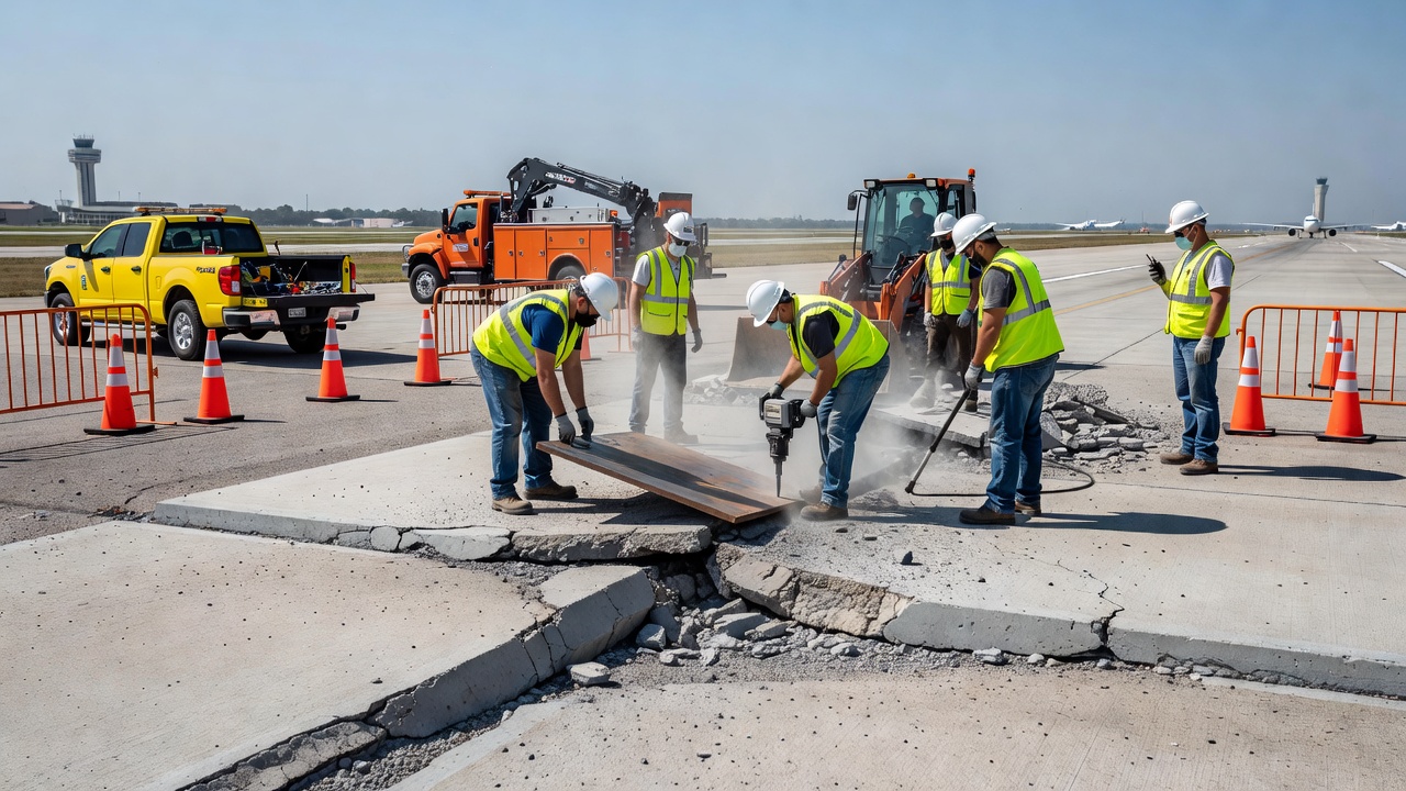
Temporary Patching
The FAA AC 150/5380-6B specifies that temporary patching of rigid pavements using flexible pavement materials (hot-mix asphalt) can be performed as an expedient repair to restore the pavement surface for immediate operational needs. The temporary patching procedure involves:
Remove shattered and loose concrete from the blowup area using jackhammers or concrete saws
Saw-cut the repair area to create straight, vertical edges at the perimeter — extend the saw cut at least 300 mm (12 inches) beyond the visibly damaged area to ensure all compromised concrete is removed
Remove debris and clean the repair cavity — use compressed air or high-pressure water to remove fine particles
Apply tack coat to the vertical faces of the existing concrete pavement
Place hot-mix asphalt in the repair cavity in lifts (typically 50–75 mm per lift), compacting each lift thoroughly
Finish and seal the surface to match the surrounding pavement elevation and apply a joint sealant at the interface between the existing concrete and the asphalt patch
The temporary patch restores the pavement surface to a trafficable condition but is not a permanent solution. The patch must be monitored and replaced with a permanent full-depth concrete repair within a specified time frame — typically within 30 to 90 days depending on traffic levels and climatic conditions.
Permanent Full-Depth Repair
Permanent repair of a blowup area involves full-depth slab replacement with structural restoration of load transfer across the repaired joint:
Full-depth saw-cutting of the affected slab to remove the entire concrete section down to the subbase
Removal and disposal of the broken concrete
Inspection and repair of the subbase layer — any pumping damage, voiding, or erosion of the subbase must be corrected before new concrete placement
Installation of load transfer devices — dowel bars at transverse joints (smooth epoxy-coated steel bars, typically 32–38 mm diameter, 450 mm long, spaced at 300 mm centers)
Placement of new concrete — rapid-setting concrete mix achieving structural strength within 4–6 hours for minimal runway closure time
Saw-cut new joints — matching the existing joint pattern at adjacent slab ends
Cure and seal — apply curing compound and install joint sealant
Evaluate and address contributing factors — inspect adjacent joints, clean accumulated debris, install pressure relief joints if indicated by the recurrence pattern
Post-Repair Evaluation
After repair, a thorough evaluation of the contributing factors should be conducted to prevent recurrence:
Joint spacing adequacy — was the original joint spacing appropriate for the aggregate CTE and climate zone?
Joint sealant condition — were adjacent joints properly sealed, or was incompressible infiltration the root cause?
ASR assessment — is the concrete reactive? Have ASR mitigation measures been considered?
Pressure relief requirement — does the pavement section need PRJ installation at regular intervals to prevent future blowups?
Setting temperature — was the original construction in cold weather such that the zero-stress temperature is low?
The evaluation findings should be documented in the pavement management system and used to update the maintenance plan for the affected pavement section and for similar sections throughout the airfield.
Summary
Blowups in concrete pavements represent one of the most hazardous distress mechanisms affecting rigid pavements, particularly on airfield movement areas where the consequences of abrupt pavement failure include potential for aircraft damage, operational disruption, and safety risk to passengers and crew. The mechanism involves thermal expansion of the concrete slab generating compressive stresses that, when unable to be accommodated by joint spaces due to incompressible material infiltration or inadequate joint design, exceed the slab’s buckling capacity and cause sudden upward displacement and fragmentation.
Prevention of blowups requires a comprehensive approach spanning design (appropriate joint spacing and width for the specific concrete CTE), construction (consideration of setting temperature and joint formation), materials management (ASR prevention, CTE-optimized aggregate selection), and maintenance (joint sealant preservation, periodic joint cleaning, and pressure relief joint installation). Detection relies on visual inspection protocols, thermal monitoring during high-risk periods, and operational reporting from airfield personnel.
The FAA and ICAO regulatory frameworks require airport operators to maintain pavements free of defects that could affect safe aircraft operations, and blowups clearly fall within this requirement. The FAA AC 150/5380-6B provides specific guidance for emergency repair and permanent restoration of blowup-affected pavements, while the FAA PASER manual (AC 150/5320-17A) provides the visual evaluation methodology for identifying and rating blowup risk during routine pavement condition surveys.
Recent research advances, including the development of the PB-RISK tool (WisDOT 2025) for predicting buckling risk based on pavement properties, construction details, aggregate type, joint condition, and climate projections, offer new capabilities for proactive blowup risk management. Integration of such predictive tools with airport pavement management systems enables operators to anticipate blowup risk during heatwave events and implement preventive measures before failure occurs, rather than responding after the hazard has materialized.
The Korea Expressway Corporation’s systematic approach to pressure relief joint installation — defining installation priority classes based on blowup history, pavement age, ASR status, and joint condition — provides a model framework for managing blowup risk in large pavement networks. The combination of proactive PRJ installation, regular joint maintenance, and monitoring of thermal conditions represents the current state of practice for blowup prevention in the most heatwave-affected regions.
Frequently Asked Questions
A blowup is a localized upward buckling or shattering of concrete pavement occurring at a transverse joint or crack during hot weather conditions. It results from compressive stresses that develop when the concrete slab expands due to rising temperature but cannot accommodate the expansion because joint spaces are filled with incompressible material, joints are too closely spaced, or the slab lacks sufficient space for horizontal movement. The accumulated compressive stress exceeds the slab's critical buckling capacity, resulting in sudden upward displacement, crushing, or shattering of the concrete. The FAA PASER manual (AC 150/5320-17A Appendix B) defines blowups as a pavement distortion defect and identifies them as a serious safety hazard requiring immediate attention.
Blowups are caused by three interacting factors: (1) thermal expansion of the concrete from high ambient temperatures generating compressive stresses within the slab, (2) insufficient space at joints to accommodate this expansion due to infiltration of incompressible materials (sand, debris, aggregate fragments) into joint spaces or inadequate original joint width, and (3) the resulting accumulation of compressive forces exceeding the slab's structural buckling resistance. Contributing factors include alkali-silica reaction (ASR) which causes additional internal expansion, excessive joint spacing, low concrete setting temperature during construction, a high coefficient of thermal expansion (CTE) of the concrete mix, and aging-related deterioration that reduces joint effectiveness.
Emergency repair of a blowup requires immediate removal of the shattered and buckled concrete, saw-cutting of the affected slab section to full depth, removal of debris, and replacement with new concrete or temporary hot-mix asphalt patch. The FAA AC 150/5380-6B specifies that temporary patching of concrete pavements using flexible pavement materials can be performed to restore the surface for immediate operational needs. Permanent repair involves full-depth slab replacement with proper load transfer dowels and re-establishment of transverse joints at appropriate spacing. In cases where blowups are recurrent, installation of pressure relief joints (PRJs) may be necessary to provide dedicated expansion space and prevent future occurrences. Cleaning and re-sealing of adjacent joints to prevent incompressible material infiltration is also critical.
Blowup prevention strategies include: ensuring adequate joint width during original construction to accommodate thermal expansion; maintaining joint sealants in good condition to prevent infiltration of incompressible material; periodic cleaning of joints to remove accumulated debris; installing pressure relief joints (PRJs) in pavements with known expansion issues; selecting concrete mixtures with low coefficient of thermal expansion (CTE); avoiding construction during cold months to achieve higher setting temperatures; managing alkali-silica reactivity (ASR) through appropriate aggregate selection; and implementing a pavement management system that includes regular condition inspections with specific attention to joint condition and expansion space adequacy.
A pressure relief joint (PRJ) is a full-depth saw-cut slot installed transversely across the full width of a concrete pavement, typically 12 to 25 mm (0.5 to 1 inch) wide, that is left unfilled or filled with a compressible material to provide dedicated expansion space for concrete slabs. PRJs relieve accumulated compressive stresses by allowing the pavement to expand into the open joint space, thereby preventing the stress buildup that leads to blowups. The FAA AC 150/5320-6F recommends PRJ installation in concrete pavements that have experienced blowups or show signs of excessive compressive stress. Research published in the KSCE Journal of Civil Engineering (Park et al., 2021) established installation spacing criteria for PRJs based on pavement age, traffic level, and observed distress severity, defining three installation priority classes for in-service roadways.
Protect Your Pavements from Thermal Distress
Prevent blowups on your airport or roadway pavements with proactive condition monitoring, joint maintenance programs, and pressure relief solutions. Ensure safe operations and extend pavement service life.
A popout is a small conical depression in a concrete pavement surface, typically 25-50 mm in diameter, caused by the expansion and expulsion of a near-surface a...
Spalling is the breaking, chipping, or loss of concrete material at pavement joints, edges, or cracks — a critical defect in airport runways, taxiways, bridges,...
A shattered slab is a portland cement concrete (PCC) pavement slab broken into four or more pieces by intersecting cracks, representing the terminal structural ...
24 min read
Pavement Distress
PCC Pavement
+4
Cookie Consent We use cookies to enhance your browsing experience and analyze our traffic. See our privacy policy.