Bridge Abutment
An abutment is the end support structure of a bridge that retains the approach embankment, transfers superstructure loads to the foundation, and accommodates th...
22 min read
Bridges
Bridge Inspection
+3
Bridge bearings are critical load-transfer devices at abutments and piers that transmit superstructure forces to the substructure while accommodating thermal movement, rotation, and seismic demands. Covers elastomeric, pot, spherical, disc, rocker, roller, and seismic isolation bearing types, FHWA SNBI condition rating, inspection protocols, distress modes, and replacement procedures.
A bridge bearing is a structural device installed at the interface between the bridge superstructure (girders, trusses, box sections, or deck) and the substructure (abutments and piers). Its purpose is deceptively simple — transfer loads and allow movement — yet the mechanical demands are severe. Bridge bearings must simultaneously resist high compressive forces from dead load and live load while permitting the subtle but constant movements from daily and seasonal temperature cycles.
The three primary functions of a bridge bearing are load transfer, rotation accommodation, and translation accommodation. Load transfer means the bearing must transmit all vertical forces (self-weight of the structure plus traffic loads) and horizontal forces (wind, braking and acceleration forces from vehicles, centrifugal forces on curved alignments, earthquake loads, and friction from thermal movements) from the superstructure into the substructure without overstressing either component. A typical bearing on a medium-span highway bridge supports several hundred tons of vertical load while resisting horizontal forces that can exceed 10% of the vertical load.
Rotation accommodation addresses the fact that bridge girders deflect under load. When a truck crosses a span, the girder ends rotate — the top flange goes into compression and the bottom flange into tension, causing a measurable angular change at the support. Even under dead load alone, prestressed concrete girders undergo long-term rotation from creep and shrinkage. A fixed bearing must allow this rotation through internal deformation or articulation. An expansion bearing must allow both rotation and horizontal translation.
Translation accommodation is the most visible function of an expansion bearing. A 40-meter steel bridge span subjected to a 50°C temperature change expands or contracts by approximately 24 mm (calculated as α × ΔT × L, where α = 12 × 10⁻⁶/°C for steel, ΔT = 50°C, and L = 40,000 mm). Over a multi-span continuous bridge, these movements accumulate at the abutments, often exceeding 100 mm of total travel. Concrete bridges experience additional long-term movements from creep and shrinkage that can equal or exceed thermal movements. Without properly functioning expansion bearings, these movements generate locked-in stresses that crack decks, distort girders, and damage substructures.
Bridge bearings are classified into two fundamental categories: fixed bearings and expansion bearings. Fixed bearings restrain horizontal translation while permitting rotation. They are typically used at intermediate piers of continuous bridges where horizontal restraint is needed to distribute braking and seismic forces. Expansion bearings permit both rotation and horizontal translation. They are installed at abutments and at selected pier locations to allow thermal and creep movements. The distribution of fixed and expansion bearings along a bridge is determined by the structural analysis to achieve the desired load path for longitudinal forces.
All bridge bearings share four basic elements regardless of type: (1) a sole plate attached to the superstructure (girder bottom flange), (2) a masonry plate resting on the substructure (pier or abutment cap), (3) the bearing element itself (elastomer, steel roller, rocker, pot, disc, or sliding surface), and (4) anchor bolts or embedded attachments that secure the bearing assembly to both the superstructure and substructure.
The variety of bridge bearing types reflects the wide range of loads, movements, and service conditions encountered across different bridge configurations. Bearing selection depends on span length, load magnitude, movement demand, rotation requirements, exposure conditions (salt, humidity, temperature extremes), seismic hazard, and maintenance access. Each type has distinct mechanical behavior, failure modes, and inspection considerations.
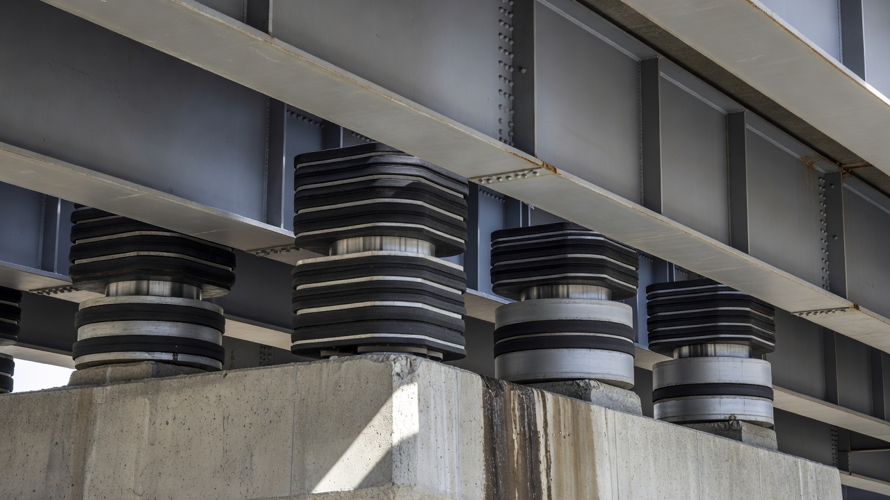
Elastomeric bearings are the most widely used type in modern highway bridge construction, particularly for spans up to 50 meters. They consist of natural rubber or neoprene (polychloroprene) pads that accommodate movement through shear deformation. The fundamental principle is that the elastomer deforms elastically in shear under horizontal load, allowing the superstructure to translate while the bearing maintains full compressive load transfer.
Two sub-types exist: plain elastomeric pads (unreinforced) and laminated elastomeric bearings (steel-reinforced). Plain pads are used only for light loads and small movements — typically on short-span bridges, pedestrian bridges, or as secondary bearing elements. They are limited by a maximum compressive stress of approximately 5 to 7 MPa and are prone to excessive bulging and extrusion if overloaded.
Laminated elastomeric bearings consist of alternating layers of elastomer and thin steel shims (typically 1.5 to 3 mm thick) vulcanized together during manufacturing. The steel shims restrain lateral bulging of the elastomer under compression, dramatically increasing the bearing vertical stiffness while maintaining the low shear stiffness needed for movement accommodation. A typical laminated bearing for a highway bridge might have 5 to 20 elastomer layers, each 8 to 12 mm thick, separated by steel shims. The bearing is bonded to top and bottom steel load plates that are bolted or welded to the superstructure and substructure.
The mechanical behavior of elastomeric bearings follows predictable engineering principles. Under vertical load, the bearing compresses — the steel shims prevent lateral expansion, so the vertical stiffness is 50 to 100 times higher than the shear stiffness. Under horizontal load, the bearing deforms in shear with a shear modulus G typically in the range of 0.6 to 1.2 MPa for natural rubber and 0.7 to 1.4 MPa for neoprene. The horizontal stiffness is calculated as K_h = (G × A) / h_rt, where A is the plan area and h_rt is the total elastomer thickness. Shear strain is limited to approximately 50% under combined dead load and thermal movement, and up to 100% under seismic loading.
Pot bearings are designed for high-load, moderate-movement applications where elastomeric bearings cannot achieve the required load capacity or rotation. They consist of a steel cylinder (the pot) containing an elastomeric disc (typically natural rubber or neoprene) that is compressed by a steel piston fitted closely inside the cylinder. A sealing ring — often a bronze or brass ring — prevents extrusion of the elastomer under high pressure.
The pot bearing works on the principle of hydrostatic confinement. The elastomeric disc is compressed inside the sealed cylinder, generating high internal hydrostatic pressure that allows the bearing to support very large vertical loads — up to 10,000 kN or more per bearing. Rotation is accommodated by the deformation of the confined elastomer, and horizontal movement is achieved through a sliding interface (typically PTFE against stainless steel) incorporated into the bearing assembly.
Pot bearings are available in two configurations: fixed pot bearings (which permit rotation only) and guided or unguided sliding pot bearings (which permit both rotation and translation). Guided bearings allow movement in one direction only (typically longitudinal), while unguided bearings permit multi-directional movement. The sliding surface is typically a PTFE (polytetrafluoroethylene) sheet bonded to the piston, bearing against a polished stainless steel counterface.
The inspection of pot bearings focuses on seal integrity. If the sealing ring deteriorates or the cylinder becomes corroded, the elastomeric disc can extrude under pressure, leading to loss of confinement and sudden loss of vertical support capacity. Section 9 of the FHWA Bridge Inspector Reference Manual emphasizes that pot bearings should be inspected for evidence of leakage around the seal piston, corrosion pitting on the cylinder wall, and condition of the PTFE sliding surface.
Spherical bearings are the preferred solution for applications requiring large rotations in multiple directions under high loads. They have no elastomeric components — instead, rotation is accommodated by a spherical convex surface (typically polished stainless steel) sliding against a matching concave surface lined with PTFE. The geometry allows rotation about any axis through the center of the sphere, providing true multi-directional rotation capacity.
Spherical bearings can be designed as fixed (rotation only) or sliding (rotation plus translation). In a fixed spherical bearing, the rotation is accommodated through the spherical interface, and the bearing is bolted rigidly at top and bottom. In a sliding spherical bearing, a second PTFE/stainless steel flat sliding interface is incorporated — typically above or below the spherical element — to provide horizontal translation. This gives the bearing both multi-directional rotation and multi-directional translation capability.
The angular rotation capacity of spherical bearings can exceed ±0.05 radians (approximately ±3 degrees), which is substantially more than most other bearing types. This makes them ideal for curved and skewed bridges, long-span structures, and bridges with significant differential settlement potential. The vertical load capacity ranges from 1,000 kN to over 30,000 kN, depending on the spherical diameter and material specifications.
Inspection of spherical bearings requires attention to the condition of the PTFE lining — wear, contamination, or displacement reduces sliding efficiency and can lock rotation. The stainless steel convex surface should be examined for scoring, pitting, or corrosion that could damage the PTFE interface. Seal systems that protect the sliding surfaces from debris and moisture should be verified intact.
Disc bearings are a modern alternative to pot bearings, using a polyether urethane (polyurethane) disc instead of a confined elastomeric pad. The urethane disc is not confined in a cylinder — it is designed to compress and deform in a controlled manner under load, providing excellent rotation capability through the elastic deformation of the disc material.
Unlike pot bearings, disc bearings do not require a sealing ring because the urethane material is inherently extrusion-resistant and does not require hydrostatic confinement. This eliminates the most common failure mode of pot bearings (seal leakage and elastomer extrusion). The urethane disc is contained between upper and lower steel plates with a central restraining ring that limits lateral deformation.
Disc bearings accommodate translation through a separate PTFE/stainless steel sliding interface, similar to pot and spherical bearings. They offer rotation capacity comparable to pot bearings (±0.02 to ±0.03 radians) with improved fatigue performance and reduced maintenance requirements. The urethane material also provides inherent damping characteristics that can be beneficial for seismic performance.
Comparison of High-Load Bearing Types:
| Parameter | Pot Bearing | Spherical Bearing | Disc Bearing |
|---|---|---|---|
| Vertical load capacity | Up to 10,000+ kN | Up to 30,000+ kN | Up to 8,000+ kN |
| Rotation mechanism | Elastomer deformation | Spherical sliding surface | Disc compression |
| Rotation capacity | ±0.02 rad typical | ±0.05+ rad typical | ±0.02–0.03 rad |
| Multi-directional rotation | Yes | Yes (true omni-directional) | Yes |
| Movement mechanism | PTFE sliding surface | PTFE sliding surface | PTFE sliding surface |
| Most common failure | Seal leakage, extrusion | PTFE wear, surface scoring | Disc aging, cracking |
| Maintenance requirement | Moderate (seal critical) | Low to moderate | Low |
| Relative cost | Moderate | High | Moderate |
Rocker bearings consist of a steel rocker element with a curved (cylindrical) bottom surface that rocks on a flat or curved masonry plate. The rotation is accommodated by the rolling contact at the curved interface, and translation is accommodated by the sliding of the top plate relative to the rocker or by the rocker itself tilting. Rocker bearings are the traditional steel bearing type used on older bridges, particularly those built in the first half of the 20th century.
Several configurations exist: single rocker bearings (one curved rocker element), segmental rocker bearings (multiple curved segments), rocker nest bearings (clusters of rocker elements), and pinned rocker bearings (a pin connection at the rocker center of rotation). The single rocker is the most common, typically consisting of a cast steel or fabricated steel rocker with a radius of curvature of 150 to 600 mm.
The fundamental behavior of a rocker bearing is determined by the radius of curvature and the coefficient of friction. As the rocker tilts, the point of contact moves along the curved surface, and the horizontal force required to produce further tilting equals the vertical load multiplied by the horizontal displacement divided by the vertical height of the rocker. This inherent restoring force must be resisted by the substructure or by supplemental restraint mechanisms.
Rocker bearings are highly susceptible to corrosion because they are exposed steel elements with limited or no corrosion protection. The curved contact surfaces are particularly vulnerable — corrosion pitting on the rocker radius or masonry plate destroys the smooth rolling interface and leads to locked movement or irregular behavior. FHWA guidance notes that rocker bearings can become unstable under seismic loading because the rocker can tilt beyond its designed range and dislodge.
Roller bearings use cylindrical steel rollers between flat bearing plates to accommodate translational movement through rolling action. They are classified as single roller bearings (one large roller) and roller nest bearings (multiple smaller rollers between parallel plates). The rollers are typically made of high-strength steel with hardened surfaces and are guided by side plates or cages to maintain alignment.
Roller bearings have inherently low friction — the coefficient of rolling friction is typically 0.01 to 0.03, substantially lower than sliding friction, meaning very low horizontal forces are required to initiate movement. This makes them effective for accommodating large translational movements on long-span bridges. The rotational capacity of roller bearings is limited — they accommodate rotation through uneven contact pressure distribution rather than through an articulated rotation interface.
The main vulnerability of roller bearings is that they require the rollers to remain parallel and correctly aligned. If corrosion, debris, or uneven loading causes the rollers to skew or bind, the bearing seizes. Roller bearings also require reliable lateral restraint to prevent the rollers from migrating sideways. Modern practice favors other bearing types (elastomeric, pot, spherical, or disc) over roller bearings for most new construction, but many historic bridges still in service rely on roller or rocker bearings.
Sliding bearings accommodate movement through relative sliding between two low-friction surfaces — typically PTFE (or a filled PTFE composite) sliding against polished stainless steel. The coefficient of friction for PTFE on stainless steel is very low under dynamic conditions (0.03 to 0.08) but higher under static conditions (0.05 to 0.12), meaning the force required to initiate movement exceeds the force required to sustain it.
Plain sliding bearings (without elastomeric or mechanical rotation components) rely on a separate articulation mechanism — either a pot, disc, spherical element, or rocker above or below the sliding interface — to accommodate rotation. In modern practice, sliding bearings are almost always combined with another bearing type to create a complete bearing assembly that handles both rotation and translation.
The PTFE sliding surface can be designed for uni-directional movement (guided sliding bearing) or multi-directional movement (unguided or pot-spherical sliding bearing). The stainless steel counterface must have a surface finish of 0.1 to 0.2 μm Ra to minimize friction and wear. Inspection focus areas include PTFE wear (reduction in thickness beyond 50% indicates need for replacement), contamination of the sliding interface by grit or debris, and corrosion of the stainless steel counterface.
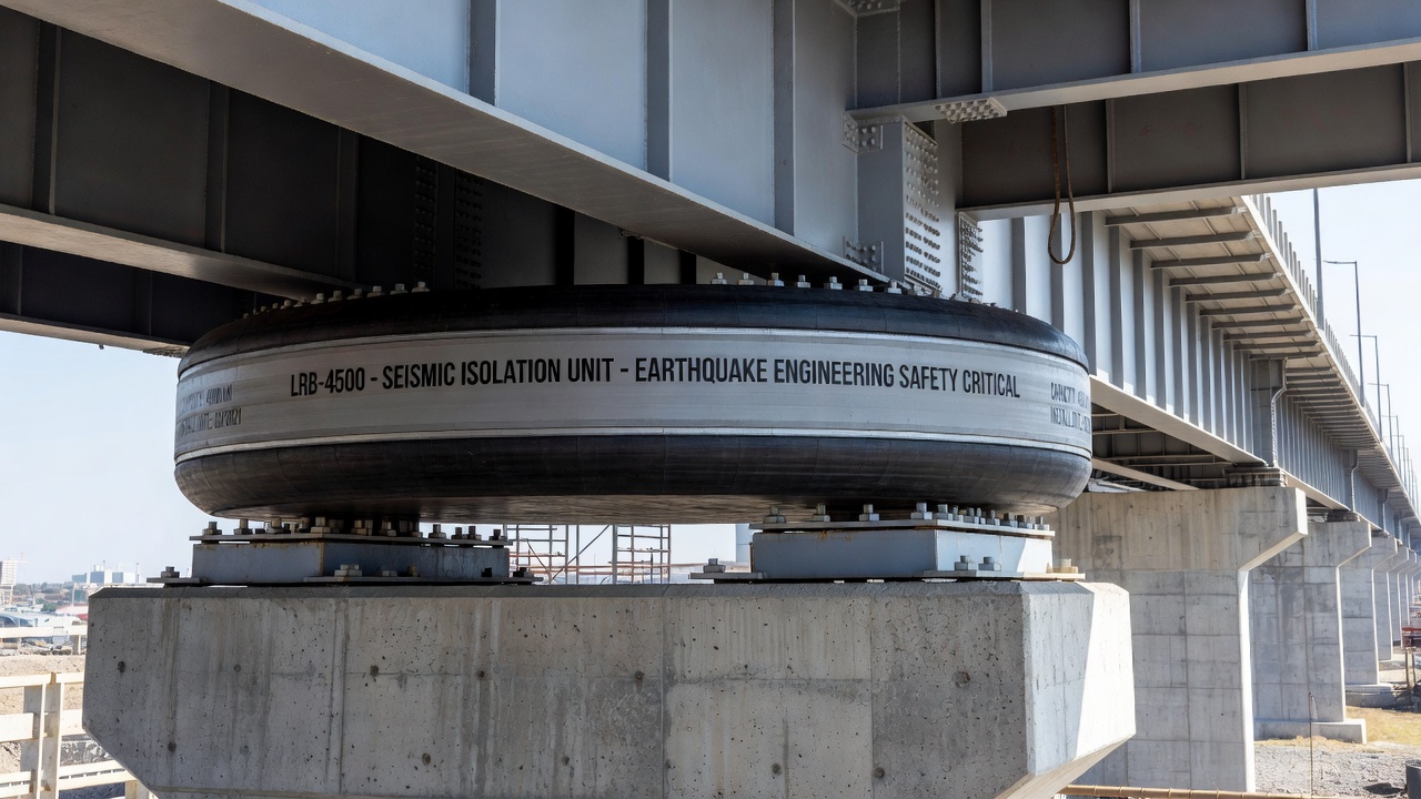
Seismic isolation bearings are a specialized category designed to protect bridges from earthquake damage by shifting the fundamental period of the structure away from the dominant frequencies of earthquake ground motion. They function by providing a flexible interface between the superstructure and substructure that decouples the bridge from ground motion, reducing seismic forces transmitted to the structure by a factor of 3 to 6 compared to a non-isolated bridge.
Two types are prequalified by Caltrans for bridge seismic isolation: Lead-Rubber Bearings (LRB) and Friction Pendulum Sliding Bearings (FPSB) .
Lead-Rubber Bearings (LRB) are elastomeric bearings with a cylindrical lead plug inserted through the center. The lead plug provides energy dissipation through plastic yielding during earthquake excitation — the lead deforms plastically at low stress (approximately 10 MPa), damping the seismic response. Under low-level loading (wind, thermal movement), the lead plug provides stiffness and prevents unwanted movement. Under earthquake loading, the lead yields, the bearing becomes flexible, and the structure natural period shifts. LRBs combine the functions of vertical support, lateral flexibility, and energy dissipation in a single compact unit.
Friction Pendulum Bearings (FPSB) consist of a concave stainless steel sliding surface and an articulated slider element faced with PTFE composite. The period of isolation is determined by the radius of curvature of the concave surface — longer radius produces longer period. The friction at the sliding interface provides energy dissipation. FPSBs have the advantage of being self-centering — after an earthquake, the weight of the structure naturally returns the slider to the lowest point of the concave surface. They can accommodate very large displacements (up to ±500 mm or more) and are suitable for both new construction and retrofit applications.
Seismic isolation bearings require specialized inspection beyond conventional bearing inspection. Key inspection items include lead plug condition (for LRBs), residual displacement after an event (indicating whether the bearing has re-centered), condition of the sliding interface (for FPSBs), evidence of yielding or fatigue, and verification that movement capacity has not been reduced by corrosion or debris.
Bridge bearings accommodate superstructure movement through three fundamental mechanisms: shear deformation, sliding, and rolling. Each mechanism involves different physics, produces different force-displacement behavior, and imposes different inspection requirements.
Shear deformation is the movement mechanism of elastomeric bearings. When the superstructure moves horizontally relative to the substructure, the elastomer layers deform in shear — the top and bottom surfaces of each elastomer layer remain bonded to the steel shims, and the elastomer itself undergoes shear strain proportional to the horizontal displacement divided by the total elastomer thickness. The restoring force generated by shear deformation is proportional to the displacement (linear elastic behavior), governed by the shear modulus G and the bearing plan area. This linear restoring force is beneficial for service-level movements because it provides a predictable, self-centering response.
Sliding is the movement mechanism of PTFE/stainless steel interfaces in pot, spherical, disc, and sliding bearings. The coefficient of friction governs the force required to initiate and sustain movement. Sliding is characterized by a stick-slip behavior — the static friction exceeds the dynamic friction, so the force required to start movement is higher than the force required to maintain it. Over time, PTFE wear, contamination, and surface deterioration can increase friction dramatically, leading to bearing seizure.
Rolling is the movement mechanism of rocker and roller bearings. The rolling friction is very low (coefficient of rolling friction 0.01 to 0.03), but the rolling interface requires precise geometry and cleanliness. Any corrosion pitting, debris, or surface damage converts the rolling contact into a sliding or sticking contact.
Bridge bearing distress can be grouped into several categories, each with distinct causes, observable indicators, and consequences. The FHWA Bridge Inspector Reference Manual (Section 9) provides detailed guidance on identifying and evaluating bearing distress during routine and in-depth inspections.
Cracking and splitting of elastomeric bearings occurs when the elastomer is subjected to excessive tensile strains, ozone exposure, or thermal cycling. In laminated bearings, cracking typically initiates at the edges of the bearing (where shear strains are highest) and propagates inward. Cracks that penetrate through multiple elastomer layers or reach the steel shims indicate advanced deterioration. The AASHTO LRFD Bridge Design Specifications limit the maximum shear strain in elastomeric bearings to ensure that tensile stresses at the edges remain within acceptable limits.
Bulging of elastomeric bearings — the lateral expansion of the free edges under vertical compression — is normal to a degree. In laminated bearings, each elastomer layer bulges independently between the steel shims. Excessive bulging indicates that the bearing is overloaded, the shim spacing is too large, or the elastomer has lost stiffness due to aging. Plain elastomeric pads (unreinforced) bulge more dramatically and can extrude laterally if the bearing is too thin relative to its plan dimensions.
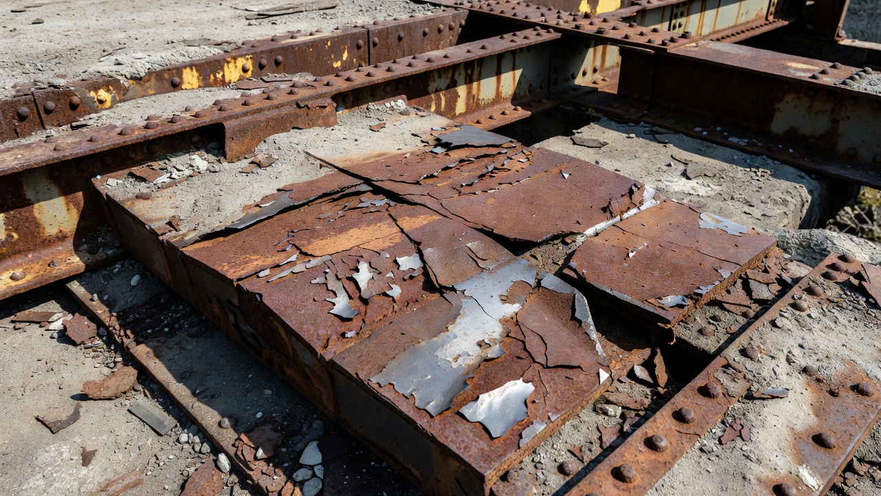
Corrosion is the dominant failure mode for steel bearings — rocker bearings, roller bearings, pot bearing cylinders, sole plates, masonry plates, and anchor bolts. Salt-laden water from leaking deck joints is the primary corrosive agent. Corrosion of load-bearing contact surfaces (rocker radius, roller surface, PTFE counterface) is particularly damaging because it locks movement. Corrosion of anchor bolts reduces the bearing ability to resist horizontal forces. Section loss of 20% or more on a load-carrying steel element is typically considered critical.
Misalignment occurs when a bearing is not correctly positioned or oriented relative to the superstructure and substructure. Causes include installation errors, differential settlement of piers or abutments, thermal displacement exceeding design assumptions, and seismic displacement. Signs of misalignment include uneven bearing gaps, eccentric contact patterns, contact marks on adjacent concrete, and visible rotation of the bearing assembly relative to its foundation.
Seized movement — the inability of an expansion bearing to translate or rotate — is one of the most consequential bearing failures. It can result from corrosion locking, debris accumulation, PTFE wear-through, or excessive friction. The consequences include induced forces in structural members, damage to expansion joints, cracking of bridge decks, and overstress of substructure elements. Seized movement is often detected during inspection by measuring the relative position of the bearing and comparing it to the expected position based on ambient temperature at the time of inspection.
Anchor bolt failure (fracture, pullout, or corrosion section loss) compromises the bearing ability to resist horizontal forces. This is particularly dangerous for fixed bearings that are relied upon to distribute braking and seismic forces to the substructure. Anchor bolt failure can allow the entire bearing to shift, leading to loss of bearing area and potential collapse of the supported girder.
Elastomer aging and hardening — over time, natural rubber and neoprene undergo chemical changes from ozone, UV exposure, and thermal cycling. The elastomer hardens, loses elasticity, and may develop surface cracking. Hardened elastomeric bearings have reduced ability to accommodate shear deformation, increasing the horizontal forces transmitted to the substructure.
Under the FHWA Specifications for the National Bridge Inventory (SNBI) , effective for data collection from January 2025 with full compliance by March 2028, bridge bearings received a dedicated condition rating field — B.C.07 Bridge Bearings Condition Rating. This is a significant change from the legacy NBI Coding Guide, where bearing condition was subsumed within the superstructure or substructure rating, often making bearing-specific deterioration invisible to asset management systems.
The B.C.07 rating uses the standard FHWA 0-to-9 General Condition Rating Scale:
| Code | Label | Description for Bearings |
|---|---|---|
| N | Not Applicable | No bearings on the structure (e.g., integral abutment bridges) |
| 9 | Excellent | No defects. Bearing appears as new with no deterioration. |
| 8 | Very Good | Isolated minor surface defects only — trace corrosion on exposed steel. |
| 7 | Good | Minor defects noted — surface corrosion on steel components, minor elastomeric weathering. |
| 6 | Satisfactory | Widespread minor or isolated moderate defects — corrosion staining, minor elastomer cracking, minor debris accumulation. |
| 5 | Fair | Some moderate defects — elastomer cracking > 3 mm, moderate corrosion of steel components, partial debris locking of movement, minor bulging. |
| 4 | Poor | Widespread moderate or isolated major defects — severe corrosion with section loss < 20%, anchor bolt corrosion, measurable misalignment, seized movement on expansion bearings, elastomer extrusion. |
| 3 | Serious | Major defects — section loss > 20% on load-carrying steel, fractured anchor bolts, bearing dislodged or significantly misaligned, complete seizure of expansion function. |
| 2 | Critical | Component severely compromised — imminent loss of vertical support capacity, bearing dislodged from seat, imminent anchor bolt failure. |
| 1 | Imminent Failure | Bearing has failed or failure is imminent — loss of vertical support, bridge should be closed to traffic. |
| 0 | Failed | Bearing has failed beyond corrective action. Bridge closed. |
A bridge classified as Poor (any component rated 4 or below) under the federal Good/Fair/Poor system triggers eligibility considerations for Highway Bridge Program funding. A rating of 3 or below on B.C.07 constitutes a Critical Finding under NBIS regulations, requiring immediate follow-up action including detailed documentation, load restriction evaluation, and scheduling of remedial action.
For National Highway System (NHS) bridges, SNBI also mandates element-level data collection per the AASHTO Manual for Bridge Element Inspection (MBEI). The bearing element is quantified across four condition states (CS1 through CS4), with the sum of quantities across all four states equaling the total bearing quantity on the bridge. This enables bridge engineers to calculate deterioration rates, model remaining service life, and plan targeted repairs.
Inspection of bridge bearings requires systematic observation of the entire bearing assembly — sole plate, bearing element, masonry plate, anchor bolts, surrounding concrete, and movement indicators. The FHWA Bridge Inspector Reference Manual dedicates Section 9 specifically to bearing inspection and evaluation.
Routine inspection of bearings includes visual observation of all accessible surfaces. The inspector should verify that the bearing is correctly positioned and aligned, that anchor bolts are intact and not corroded, that the bearing element shows no signs of deterioration or overload, and that movement is occurring as designed. For expansion bearings, the inspector should measure the gap between bearing components and correlate the measured position with the ambient temperature at the time of inspection.
Inspection of specific bearing types:
For elastomeric bearings, the inspector evaluates the condition of the visible elastomer surfaces including free edges between laminations. The bearing is examined for cracking, splitting, bulging, delamination of the elastomer from the steel shims, and evidence of extrusion. Delamination is identified by the separation of the elastomer from the steel shim at the edges.
For pot bearings, the critical inspection item is the seal. The inspector checks for evidence of elastomer extrusion past the seal ring, which appears as a thin film or bulge of rubber at the piston-cylinder interface. Corrosion pitting on the exposed cylinder wall should be measured for depth to assess section loss.
For spherical bearings, the inspector verifies that the spherical interface is free to rotate and that the PTFE lining has not worn through or displaced. Stainless steel surfaces are inspected for scoring, pitting, or corrosion staining that could increase friction.
For rocker and roller bearings, the inspector examines the curved contact surfaces for corrosion pitting that would disrupt rolling. The rocker should be plumb (vertical) under normal conditions — tilting beyond design limits indicates anchor bolt failure or bearing dislodgment.
For sliding bearings, the PTFE and stainless steel interface is the primary inspection target. PTFE wear beyond 50% of original thickness is considered critical. Contamination of the sliding interface by grit, deicing salt residue, or debris should be documented.
Inspection frequency is governed by NBIS requirements — routine inspection at intervals not exceeding 24 months for most bridges. Bridges with known bearing deficiencies, fracture-critical members, or seismic vulnerability may require more frequent inspection. In-depth bearing inspection (removing covers, cleaning surfaces, taking measurements) is typically performed at intervals of 5 to 10 years or when routine inspection indicates a potential problem.
Bearing failure cascades into secondary damage throughout the bridge structure, often at costs far exceeding the bearing replacement itself. Understanding these failure consequences is essential for prioritizing bearing maintenance and replacement.
Girder overstress occurs when a seized expansion bearing prevents the girder from moving freely under thermal expansion. Instead of the bearing accommodating the movement, the girder itself must absorb the thermal strain. For a steel girder, a 30°C temperature increase restrained over a 30-meter length induces a compressive stress of approximately 72 MPa (σ = α × ΔT × E = 12×10⁻⁶ × 30 × 200,000) — nearly 25% of the yield stress of typical structural steel. Over several thermal cycles, this can cause permanent distortion of the girder, local buckling at the supports, or fatigue cracking.
Deck and expansion joint damage is the most common secondary effect of bearing failure. When bearings lock, the deck joints (which are designed for specific movement ranges) are forced beyond their limits. Compression-type joints buckle and extrude. Open joints may have their steel nosing torn from the concrete. Waterproofing membranes at joints are torn, allowing water and deicing salts to reach the bearings — accelerating the very corrosion that caused the problem.
Substructure cracking results from transmitted forces that the substructure was not designed to resist. A stuck expansion bearing on a pier can transmit horizontal forces from thermal expansion into the pier cap, columns, or abutment wall, causing diagonal tension cracking. Over multiple thermal cycles, these cracks widen and propagate, potentially requiring pier rehabilitation.
Loss of vertical support is the most severe consequence — though rare, it occurs when bearing components fail catastrophically. A pot bearing that loses seal confinement can extrude its elastomeric disc, suddenly dropping the supported girder by several millimeters.
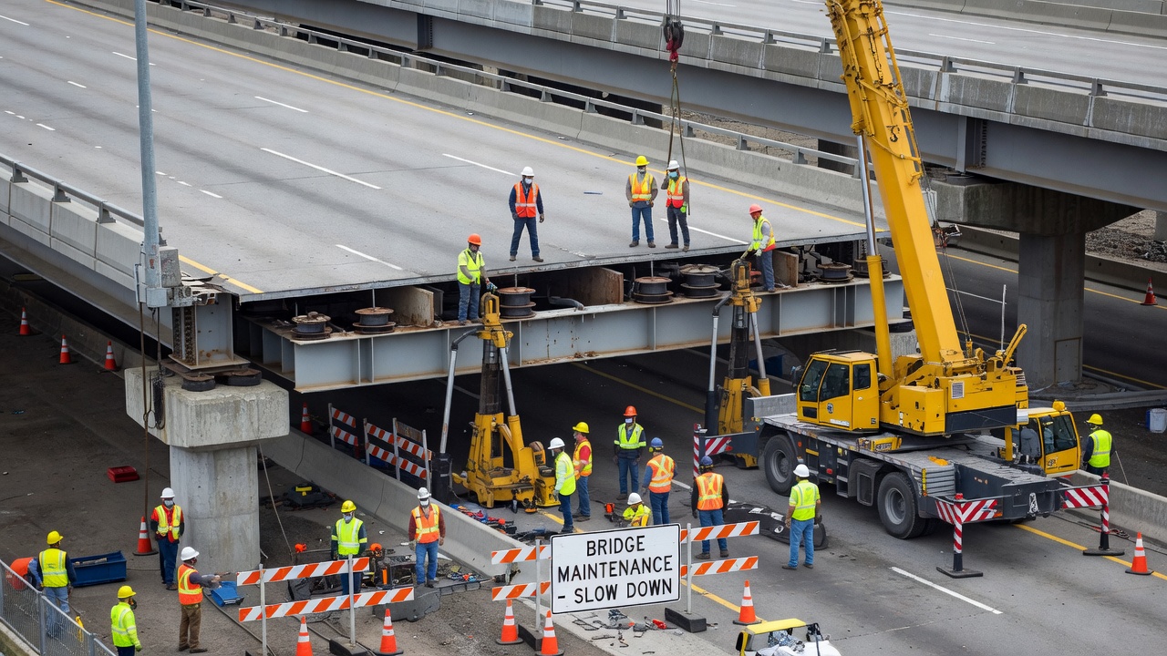
Bridge bearing replacement is a highly controlled structural operation that requires precision jacking, temporary support, and systematic load transfer. The FHWA Bridge Maintenance: Superstructure manual notes that the only maintenance that does not require jacking is cleaning and keeping debris from accumulating around the bearing assembly.
The jacking process begins with installing hydraulic cylinders (jacks) adjacent to each bearing that requires replacement. The jacks support the superstructure at hard points — typically at beam end stiffeners, cross-frame connections, or directly at the bearing sole plate. High-tonnage locknut cylinders (hydraulic cylinders with mechanical locknuts) are standard equipment because they can hold the load indefinitely after the hydraulic pressure is released, ensuring safety during the bearing swap.
Synchronous lifting is essential for bridges with multiple jacking points. If jacks are not synchronized, differential displacements between jacking points can overstress the structure. Split-flow pumps or synchronous lifting pumps (such as Enerpac EVO systems) control up to 12 jacking points simultaneously, maintaining accuracy within 1 mm (0.040 inches) between leading and lagging cylinders.
The typical replacement sequence is:
Post-installation inspection is critical. The inspector must verify that the new bearing is correctly oriented (expansion direction, fixed vs. expansion designation), that anchor bolts are properly torqued, that movement is unobstructed, and that the bearing elevation matches the adjacent supports.
A growing trend in bridge design that directly impacts bearing demand is the integral abutment bridge — a jointless structure where the superstructure is rigidly connected to the abutment, eliminating the need for deck joints and bearings at the bridge ends. In semi-integral abutment designs, the deck is connected to the abutment but the abutment is free to rotate on a foundation bearing.
Integral abutment bridges accommodate thermal movements through the flexure of the abutment piles and the flexibility of the approach fill. This eliminates the two most maintenance-intensive bridge components (bearings and expansion joints) but imposes new demands on the abutment foundation and approach pavement design.
The FHWA has actively promoted integral abutment construction since the 1980s, and many state DOTs now specify integral abutments for bridges with total length up to 150 to 200 meters (depending on skew, foundation soil, and thermal range). For longer bridges or bridges on fixed piers, mid-span bearings remain necessary.
Seismic isolation bearings merit separate discussion because their function extends beyond conventional load transfer and movement accommodation — they actively improve the structural response of the bridge during earthquakes.
The principle of seismic isolation is period shift. A non-isolated bridge has a natural period typically in the range of 0.2 to 0.8 seconds — within the dominant energy range of most earthquakes. The structure therefore experiences high seismic acceleration forces. By introducing flexible bearings at the superstructure-substructure interface, the natural period of an isolated bridge shifts to 1.5 to 3.0 seconds, moving the structure away from the earthquake dominant energy content and reducing base shear by 60% to 80%.
Lead-Rubber Bearings (LRB) combine low shear stiffness (for period shift) with high damping (for energy dissipation). The lead plug yields at a stress of approximately 10 MPa, providing a stable hysteretic energy dissipation mechanism. The elastomeric component provides the restoring force and vertical load capacity. After the earthquake, the elastomeric restoring force returns the bearing to its original position, though some residual displacement (typically 5 to 20 mm) may remain if the lead plug has yielded.
Friction Pendulum Bearings (FPSB) operate on a different principle — the period of isolation is determined by the radius of curvature of the concave surface (T = 2π√(R/g), where R is the radius and g is gravity). A radius of 2 meters produces a period of approximately 2.8 seconds regardless of the supported weight — the period is independent of the mass, which is a significant advantage for bridges with variable dead load.
The FPSB accommodates displacement through the slider moving up the concave surface, with the weight of the structure providing the restoring force. The friction coefficient of the PTFE-stainless steel interface (typically 0.05 to 0.12) provides the energy dissipation. FPSBs are self-centering because the weight of the structure always returns the slider to the lowest point of the concave surface.
Seismic isolation bearings require a clearance gap around the bearing to accommodate the design displacement without impact with adjacent structure. The design displacement is calculated from the seismic hazard, the period of the isolated structure, and the target performance level. For a bridge in a region of high seismicity, the design displacement can exceed ±300 mm, requiring substantial clearance zones.
Inspection of seismic isolation bearings is more demanding than conventional bearings. The inspector must verify: (1) that the displacement capacity has not been reduced by debris or adjacent structure encroachment, (2) that the bearing shows no sign of yielding or damage from previous seismic events (unless approved by design), (3) that protective covers and seals are intact, (4) that residual displacement after a seismic event is within acceptable limits, and (5) that lead plugs (for LRBs) show no evidence of deterioration or cavitation.
Proactive bearing maintenance is substantially more cost-effective than reactive replacement.
Cleaning is the most fundamental maintenance activity. Debris accumulation around bearings traps moisture and deicing salts, accelerates corrosion, and physically blocks movement. Bearings should be cleaned during each routine inspection — removing debris, mud, bird nests, and vegetation from the bearing area.
Drainage maintenance prevents water from reaching the bearings. Weep holes in pier caps and abutment backwalls must be kept clear. Deck joints above bearings should be maintained to prevent leakage. If a deck joint is leaking above a bearing, joint repair should be prioritized to prevent continued bearing exposure to corrosive runoff.
Lubrication of sliding bearings and rocker/roller contact surfaces is required for some bearing types. Lubrication is typically performed with the deck raised slightly using hydraulic jacks to allow lubricant to be pumped into the aperture. The lubricant type must be compatible with the bearing materials.
Corrosion protection — steel bearing components should have their protective coating maintained. Flaking or bubbling paint around steel bearings should be cleaned and recoated. Galvanized components should be inspected for zinc depletion.
Movement verification should be performed during every routine inspection. For expansion bearings, the inspector should record the measured opening gap and the ambient temperature. Comparing this measurement to the design relationship between temperature and displacement provides a direct check on movement functionality.
Monitoring programs — for bridges with known bearing vulnerabilities, automated monitoring can provide early detection. Linear variable differential transformers (LVDTs), inclinometers, and strain gauges can be installed on critical bearings with data logged during thermal cycles and traffic loading. The data enables trend analysis and early detection of developing movement problems before they cause secondary damage.
Bridge bearings are among the most maintenance-critical components in any structure. Regular inspection per FHWA SNBI standards and timely replacement prevent cascading structural damage. Contact TarmacView for expert guidance on bridge bearing inspection, condition assessment, and maintenance planning for your infrastructure assets.
An abutment is the end support structure of a bridge that retains the approach embankment, transfers superstructure loads to the foundation, and accommodates th...
A bridge pier is an intermediate vertical support structure between abutments that transfers superstructure loads to the foundation. Multi-column bents, wall pi...
Bridge girders are the primary horizontal load-carrying beams supporting the bridge deck, spanning between piers and abutments. Common types include steel I-gir...