Carbonation is the chemical reaction of atmospheric CO₂ with calcium hydroxide and other hydration products in concrete, progressively reducing the pH of the concrete pore solution from ~13 to below 9. This destroys the passive protective layer on reinforcing steel, enabling corrosion even without chlorides. Covers carbonation depth measurement, rate factors, and implications for reinforced concrete inspection.
Carbonation of Concrete Structures
Definition and Chemistry of Concrete Carbonation
Carbonation of concrete is a physicochemical process in which atmospheric carbon dioxide (CO₂) diffuses into the porous structure of concrete and reacts with alkaline components of the hydrated cement paste. The primary reaction involves calcium hydroxide — also known by its mineralogical name portlandite, Ca(OH)₂ — which is a major hydration product of Portland cement. The reaction produces calcium carbonate (CaCO₃, predominantly the mineral calcite) and water according to the following stoichiometric equation:
Ca(OH)₂ + CO₂ → CaCO₃ + H₂O
This reaction is fundamentally a neutralization process. Calcium hydroxide provides the highly alkaline environment characteristic of concrete, dissolving into the pore water to maintain a pH typically between 12.5 and 13.5. The conversion of Ca(OH)₂ to CaCO₃ depletes the hydroxide ions (OH⁻) in the pore solution, causing the pH to drop progressively toward the near-neutral range of 8.0 to 9.0.
However, carbonation is not limited to calcium hydroxide alone. Secondary carbonation reactions involve other hydrated phases in the cement paste. The calcium silicate hydrate (C-S-H) gel, which is the primary binding phase providing mechanical strength to hardened concrete, also undergoes carbonation according to the general reaction:
C-S-H + CO₂ → CaCO₃ + amorphous silica gel + H₂O
The C-S-H carbonation is thermodynamically favored when the portlandite supply becomes depleted. This secondary reaction is particularly significant because it consumes the calcium from the C-S-H structure, altering the gel’s composition and potentially increasing the porosity of the paste. Additional cementitious phases susceptible to carbonation include ettingite (calcium sulfoaluminate hydrate), monosulfate, and calcium aluminate hydrates. The overall carbonation process is therefore not a single reaction but a complex, sequential set of chemical transformations that progressively consume the alkaline reservoir of the concrete.
The carbonation of C-S-H is especially important for concretes containing supplementary cementitious materials (SCMs) such as fly ash, ground granulated blast-furnace slag (GGBFS), and silica fume. These blended cement systems typically have lower portlandite content because the pozzolanic reaction consumes Ca(OH)₂ to form additional C-S-H. Consequently, the reduced alkaline buffer capacity makes SCM concretes potentially more susceptible to pH reduction from carbonation, even if their refined pore structure partially offsets the increased CO₂ diffusion rate.
The Carbonation Process and pH Reduction Mechanism
The carbonation process follows a well-defined sequence that begins at the exposed concrete surface and advances inward over time. The reaction requires the simultaneous presence of three essential components: CO₂, water, and reactive hydrate phases. The mechanism involves several intermediate steps that govern the overall rate.
Step 1 — CO₂ Transport: Gaseous CO₂ from the atmosphere enters the concrete pore system through diffusion. This transport is driven by the concentration gradient between the higher CO₂ level in ambient air (approximately 0.04% by volume or 400 ppm) and the interior of the concrete, where CO₂ is consumed by the carbonation reaction. The diffusion coefficient depends heavily on the pore structure and moisture state of the concrete.
Step 2 — Dissolution in Pore Water: Once inside the pore system, CO₂ dissolves into the alkaline pore water to form carbonic acid (H₂CO₃) , which rapidly dissociates into bicarbonate (HCO₃⁻) and carbonate (CO₃²⁻) ions:
CO₂(g) + H₂O ⇌ H₂CO₃ ⇌ H⁺ + HCO₃⁻ ⇌ 2H⁺ + CO₃²⁻
Step 3 — Neutralization: The hydrogen ions (H⁺) released by carbonic acid dissociation react with hydroxide ions (OH⁻) in the highly alkaline pore solution. This consumption of OH⁻ reduces the pH. Simultaneously, the carbonate ions react with calcium ions (Ca²⁺) dissolved from portlandite to precipitate calcium carbonate.
Step 4 — Precipitation: Calcium carbonate precipitates as a solid phase within the pores, primarily as the mineral calcite, although aragonite and vaterite polymorphs can also form under specific conditions. This precipitation can initially fill pore spaces, reducing porosity in the carbonated zone, which is a paradoxical beneficial effect discussed later.
The most critical consequence of this pH reduction is the destabilization of the passive film on embedded steel reinforcement. In normal, uncarbonated concrete, the high pH (12.5–13.5) maintains a thin, protective γ-Fe₂O₃ (maghemite) oxide layer — the passive film — on the steel surface. This film is thermodynamically stable at pH values above approximately 9.5 and effectively prevents iron dissolution. Once carbonation reduces the local pH below this threshold, the passive film becomes thermodynamically unstable and begins to dissolve, leaving the steel vulnerable to corrosion if moisture and oxygen are present.
The carbonation process is autocatalytic in some respects: as calcium carbonate precipitates and fills pores, the porosity reduction can slow further CO₂ diffusion. However, the carbonation of C-S-H gel can simultaneously increase porosity by removing calcium from the gel structure. The net effect on transport properties depends on the stage of carbonation and the original concrete quality.
Carbonation Front Propagation and Depth Modeling
The carbonation front is defined as the boundary region within the concrete where the pH transitions from the alkaline uncarbonated state (pH > 12) to the near-neutral carbonated state (pH < 9). This front does not advance as a perfectly sharp interface but rather as a transition zone, typically 1–5 mm in width, where partial carbonation of different hydrate phases occurs.
According to the RILEM TC 281-CCC (CPC-18R1) standard definition: the carbonation front is the location in the sample at which an observable pH change occurs. Material between the sample surface and the carbonation front is considered carbonated; material deeper than the carbonation front is considered uncarbonated. The carbonation depth (d_k) is the perpendicular distance from the sample surface to the mean position of this front.
The propagation of the carbonation front follows a square-root-of-time relationship that is well established in concrete science:
d = k × √t
where:
d = carbonation depth (mm)
k = carbonation coefficient (mm/√year)
t = exposure time (years)
This relationship derives from Fick’s second law of diffusion, which governs the transport of CO₂ through the concrete pore system. The carbonation coefficient k is the single most important parameter characterizing the carbonation resistance of a particular concrete under specific environmental conditions. Typical values for different concrete qualities are summarized below:
Concrete Quality
Water-Cement Ratio
Carbonation Coefficient k (mm/√year)
Carbonation Depth After 50 Years
High-quality, dense
0.35–0.45
2–4
14–28 mm
Moderate quality
0.45–0.55
5–8
35–57 mm
Poor-quality, permeable
0.55–0.65
8–12
57–85 mm
Very poor quality
> 0.65
12–20
85–141 mm
It is critical to understand that the square-root law is valid only under constant environmental conditions. Real structures experience seasonal and diurnal variations in temperature, humidity, and CO₂ concentration that modify the instantaneous carbonation rate. More advanced carbonation models incorporate time-dependent environmental parameters using cumulative damage approaches or finite element analysis of coupled heat, moisture, and CO₂ transport.
The RILEM CPC-18R1 recommendation, published in 2026 as an update of the original 1988 CPC-18 test method, provides the authoritative framework for measuring carbonation depth. This standardized method enhances comparability of results across different laboratories and site investigations, and is adopted as the reference method in European standard EN 14630:2006 (Products and systems for the protection and repair of concrete structures — Determination of carbonation depth).
Factors Affecting the Carbonation Rate
The rate at which carbonation progresses through concrete depends on a complex interplay of environmental factors, material properties, and construction quality. Understanding these factors is essential for predicting service life and designing durable structures.
CO₂ Concentration
The carbonation rate is directly proportional to the square root of the ambient CO₂ concentration. In urban environments, CO₂ levels typically range from 350–600 ppm due to traffic and industrial emissions, while rural areas have concentrations near the global average of approximately 400 ppm. Indoor environments can have elevated CO₂ levels from human respiration, potentially reaching 1000–2000 ppm in poorly ventilated spaces. This concentration differential explains why indoor concrete structures (such as parking garages) often carbonate faster than their outdoor equivalents. The accelerating effect of CO₂ concentration is the basis for accelerated carbonation testing, where specimens are exposed to 1–4% CO₂ (25–100 times atmospheric levels) to simulate decades of natural carbonation within weeks.
Relative Humidity
Relative humidity (RH) is arguably the most critical environmental factor controlling carbonation rate. The relationship is parabolic, with maximum carbonation rates occurring at 50–70% RH. At this optimal moisture range, the pore network contains sufficient water to dissolve CO₂ and facilitate the ionic reactions, but enough air-filled pore space to allow rapid gas diffusion.
RH Range
Carbonation Rate
Explanation
< 40%
Very slow
Insufficient water to dissolve CO₂ and support the aqueous reaction
40–50%
Moderate
Limited water availability restricts reaction
50–70%
Maximum
Optimal balance of gas diffusion and aqueous reaction
70–90%
Moderate
Increased water saturation restricts CO₂ diffusion
> 90%
Very slow / near zero
Water-filled pores nearly block gas diffusion
Fully saturated (immersed)
Near zero
No gaseous CO₂ transport possible
This RH dependence has important practical implications. Concrete elements exposed to rain followed by drying cycles (such as bridge decks and parapets) experience accelerated carbonation during the drying phase. Conversely, permanently submerged concrete (such as foundation piles in water) does not carbonate.
Concrete Quality and Mix Design
Water-cement ratio (w/c) is the single most influential mix design parameter. Lower w/c ratios produce denser concrete with reduced porosity and higher strength, directly lowering CO₂ diffusivity. The relationship between w/c and carbonation resistance is approximately exponential: increasing w/c from 0.40 to 0.60 can increase the carbonation coefficient by a factor of 3–6.
Cement type significantly affects carbonation resistance. CEM I (Portland cement) concretes have the highest portlandite content and therefore the greatest alkaline buffer capacity. Blended cements with fly ash (CEM II/B-V, CEM IV) or slag (CEM III) have lower portlandite due to pozzolanic reactions, which theoretically makes them more susceptible to pH reduction. However, the pore structure refinement from SCMs can partially offset this by reducing CO₂ diffusivity. The net effect depends on the replacement level, curing conditions, and exposure environment. At typical replacement levels (20–35% fly ash, 40–60% slag), properly cured SCM concretes often exhibit comparable or even superior carbonation resistance to plain Portland cement concrete.
Cement Type
Portlandite Content
Relative Carbonation Rate
CEM I (Portland)
High
Reference (1.0×)
CEM II/A-L (limestone)
Medium-High
1.1–1.3×
CEM II/B-V (25% fly ash)
Medium
1.3–1.8×
CEM III/A (40% slag)
Medium
1.2–1.6×
CEM III/B (70% slag)
Low
1.5–2.5×
CEM IV (pozzolanic)
Low-Medium
1.5–2.0×
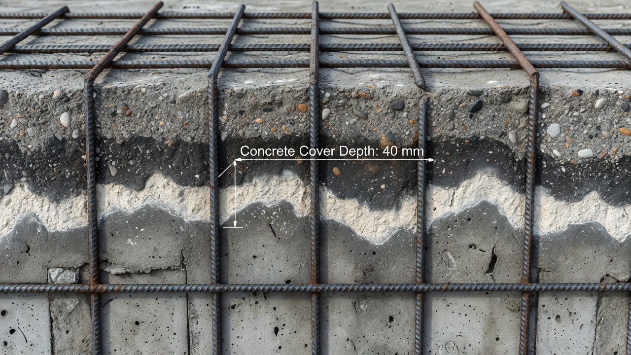
Concrete Cover Depth
The depth of concrete cover over reinforcement is the primary structural design parameter that determines the time to corrosion initiation from carbonation. The cover must exceed the expected carbonation depth at the design service life, plus an appropriate safety margin. Current standards specify minimum cover depths based on environmental exposure classes:
ACI 318-19: Interior exposure — 38 mm; Exterior exposure (weather) — 50 mm; Concrete cast against earth — 75 mm
FAA AC 150/5320-6G (airport pavements): Concrete cover over top reinforcement — 75–100 mm minimum
The time for the carbonation front to reach the reinforcement (initiation time, t_init) can be estimated by solving the square-root law for t:
t_init = (cover depth / k)²
For example, with a cover depth of 40 mm and a moderate concrete quality (k = 6 mm/√year), the initiation time is approximately 44 years. Increasing the cover to 55 mm extends this to over 84 years.
Cracking and Construction Defects
Cracks, honeycombing, and construction joints provide preferential pathways for CO₂ ingress, dramatically accelerating local carbonation. A crack can allow carbonation to penetrate to the depth of the crack almost instantaneously relative to bulk diffusion. The WJE Primer on concrete carbonation explicitly demonstrates this effect, noting that carbonation depth is consistently deeper along crack faces compared to the adjacent sound concrete.
The presence of a crack at the concrete surface effectively reduces the cover depth to zero at that location, meaning the carbonation front can reach the reinforcement within months or years rather than decades. This is why crack control is essential for durability: cracks wider than 0.2–0.3 mm are generally considered to compromise carbonation resistance and require sealing or repair.
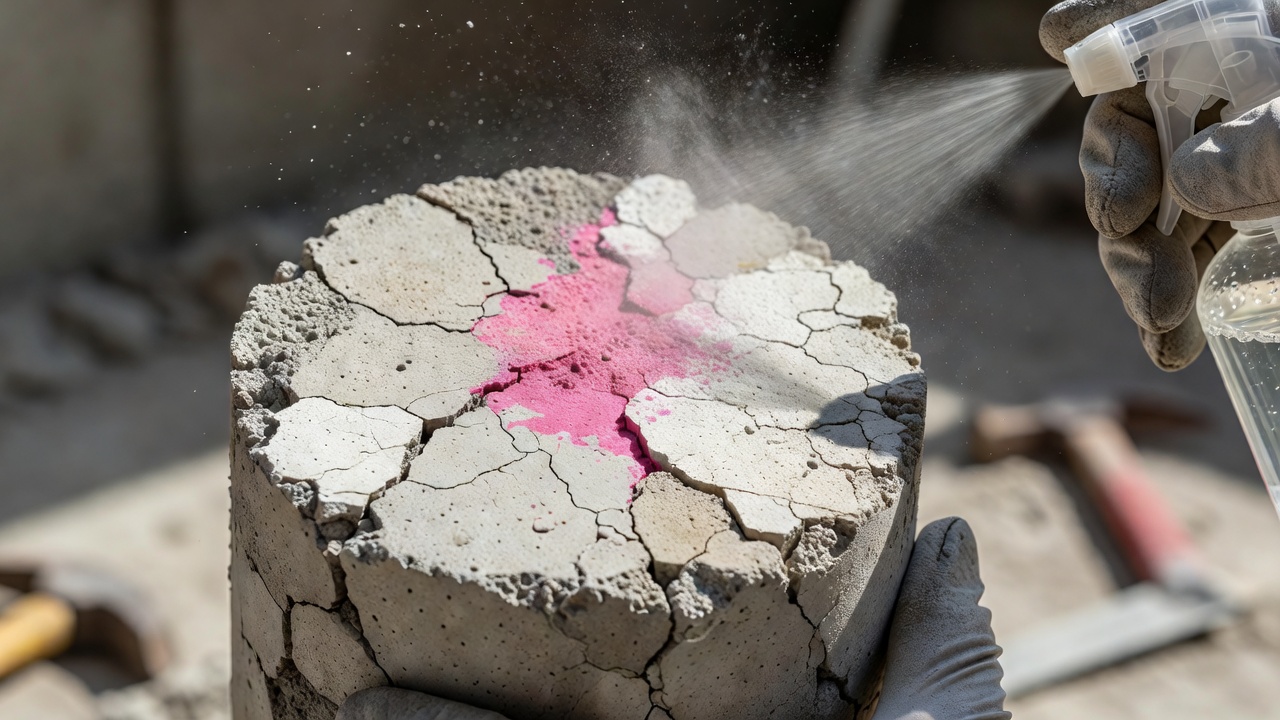
Carbonation Depth Measurement: The Phenolphthalein Test
The phenolphthalein spray test is the standard method for determining carbonation depth in concrete structures, specified by RILEM CPC-18R1, EN 14630:2006, and numerous national standards. The method is classified as semi-destructive, requiring a freshly exposed concrete surface on a core sample, drilled hole, or deliberately fractured element.
Procedure
Sample extraction: A concrete core (typically 50–100 mm diameter) is extracted from the structure, or a fresh fracture surface is created. The surface to be tested must be approximately perpendicular to the exposed surface of the structure.
Surface preparation: The test surface must be freshly exposed — within 15 minutes of cutting or extracting — to minimize additional carbonation from ambient air during the test. The surface should be cleaned of dust and loose particles and dried using compressed air or a hair dryer to remove any bleed water that could cause stain migration.
Indicator application: A 1% phenolphthalein solution (0.8–1.0 g phenolphthalein powder dissolved in 70 mL ethanol and 30 mL deionized water) is sprayed or applied to the test surface. Multiple light sprays are recommended rather than a single heavy application.
Color development: The color change occurs within seconds. The full color develops over 1–2 minutes. In areas where the pH exceeds approximately 9.5, the solution turns bright pink/magenta (fuchsia), indicating uncarbonated concrete. Carbonated areas with pH below 9.5 remain colorless.
Measurement: The perpendicular distance from the exposed surface to the color change boundary is measured at multiple points (typically 5–20 measurements per core face) using a ruler or digital caliper. The mean carbonation depth and maximum carbonation depth are reported.
Indicator Alternatives
Due to regulatory concerns about phenolphthalein — classified by the European Chemicals Agency (ECHA) under REACH as a substance of very high concern (SVHC) due to carcinogenicity — alternative pH indicators are increasingly used:
Indicator
Solution Details
pH Transition Range
Color Change (low → high pH)
Phenolphthalein
1% in 70/30 ethanol/water
8.2–10.0
Colorless → Fuchsia
Thymolphthalein
0.1% in 90/10 ethanol/water
9.3–10.5
Colorless → Blue
Curcumin (turmeric)
0.1–0.3% in 100% ethanol
7.5–9.2
Yellow → Red/Brown
Black carrot anthocyanin
~2.5% in 70/30 ethanol/water
6.5–8.0
Yellow → Red/Purple
The RILEM CPC-18R1 recommendation acknowledges that thymolphthalein detects pH changes closer to the actual corrosion risk threshold (pH 9.3–10.5) and is a safer alternative. However, results from different indicator types are not directly comparable due to differing pH transition ranges. Regardless of the indicator used, thin-section petrographic examination (per ASTM C856) is considered the most definitive method for evaluating carbonation when ambiguous results are obtained, because carbonated portland cement paste exhibits characteristic golden bright birefringence under cross-polarized light microscopy.
Relationship Between Carbonation and Rebar Corrosion
The connection between carbonation and reinforcement corrosion follows the well-established Tuutti corrosion model, which divides the service life of a reinforced concrete structure into two distinct phases: the initiation phase and the propagation phase.
Initiation Phase
During the initiation phase, CO₂ diffuses through the concrete cover toward the reinforcement. The carbonation front advances progressively, consuming the alkaline reserve of the cement paste. Throughout this phase, the concrete remains visually sound, and there is no structural damage. The passive film on the reinforcement remains intact as long as the carbonation front has not reached the steel depth.
The initiation phase ends when the carbonation front reaches the reinforcement bar. At this point, the pH in the immediate vicinity of the steel drops below approximately 9.5, and the passive γ-Fe₂O₃ film becomes thermodynamically unstable. The duration of the initiation phase is determined by:
t_init = (cover depth / k)²
Propagation Phase
Once the passive film is destroyed, corrosion propagation begins. The corrosion of steel in carbonated concrete is an electrochemical process requiring:
Anodic reaction: Fe → Fe²⁺ + 2e⁻ (iron dissolution at the steel surface)
Cathodic reaction: O₂ + 2H₂O + 4e⁻ → 4OH⁻ (oxygen reduction at the steel surface)
The corrosion rate in carbonated concrete is controlled by the electrical resistivity of the concrete and the availability of oxygen at the steel surface. Carbonated concrete typically has higher resistivity than uncarbonated concrete due to pore filling by calcium carbonate, which can slow the corrosion rate once initiated. However, the corrosion products — primarily Fe(OH)₃ (ferric hydroxide) , Fe₂O₃ (hematite) , and Fe₃O₄ (magnetite) — occupy a volume 2–6 times greater than the original steel. This volumetric expansion generates tensile stresses in the surrounding concrete, leading to:
Cracking of the concrete cover along the line of the reinforcement
Delamination of the concrete cover (horizontal cracking along the reinforcement plane)
Spalling — detachment of concrete cover fragments
Loss of steel cross-section — reduction in load-bearing capacity of the reinforcement
Unlike chloride-induced corrosion, which produces localized pitting and is difficult to detect visually in early stages, carbonation-induced corrosion tends to produce relatively uniform corrosion across the affected steel surface. This uniform attack is easier to predict and model but can still lead to catastrophic structural failure if left unmanaged.
The Morandi Bridge collapse in Genoa, Italy (2018) has been cited as a case where carbonation-induced corrosion played a contributing role. The collapse investigation revealed extensive carbonation of the concrete post-tensioning ducts, which had compromised the protective alkaline environment around the prestressing steel, initiating corrosion that reduced the steel cross-section over decades.
Carbonation in Concrete Bridges and Buildings
Bridges and buildings represent the largest inventory of reinforced concrete infrastructure worldwide, and both are susceptible to carbonation-induced deterioration. The specific risks and inspection approaches differ between these structure types.
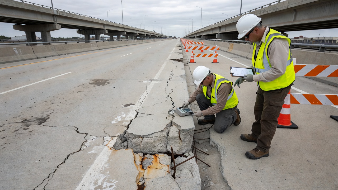
Bridge Structures
Highway bridges are particularly vulnerable to carbonation for several reasons. Bridge decks are exposed to vehicular exhaust containing elevated CO₂ levels, cyclic wetting and drying from rain and deicing salts, and mechanical loading that can cause cracking — all factors that accelerate carbonation. Bridge substructures (piers, abutments, columns) in urban areas face similar CO₂ exposure, with splash zones experiencing accelerated deterioration.
The EU-funded BRIME project (Bridge Management in Europe, ~2001) reported that highway bridges in France, the UK, and Germany showed deficiencies at rates of 39%, 30%, and 37% respectively, with the primary cause being reinforcement corrosion driven largely by carbonation. These findings underscore the widespread nature of the problem across European infrastructure.
Inspection protocols for bridge carbonation typically involve:
Core extraction at representative locations (supports, midspan, joints)
Phenolphthalein testing on core faces and drilled holes
Cover depth measurement using cover meters
Half-cell potential mapping to identify active corrosion zones
Electrical resistivity measurements to assess corrosion rate potential
Petrographic examination of selected cores for microscopic carbonation assessment
Building Structures
Parking garages are among the most carbonation-prone building structures due to:
High CO₂ concentrations from vehicle exhaust (up to 2000–3000 ppm)
Frequent wet-dry cycles from water and deicing salts tracked in by vehicles
Typically slender structural members (slabs, beams) with limited cover depth
Residential and commercial buildings constructed before the 1970s often have substandard cover depths and higher water-cement ratios compared to modern standards. These older structures are now reaching an age (50–70 years) where carbonation-induced corrosion is becoming apparent. The 2021 Surfside condominium collapse in Miami, while primarily attributed to chloride-induced corrosion from the coastal environment, highlighted the consequences of undetected reinforcement corrosion in aging concrete buildings.
Condition assessment of buildings for carbonation typically follows a tiered approach:
Visual inspection — mapping areas of cracking, rust staining, and spalling
Carbonation depth screening — phenolphthalein testing at representative locations
Detailed investigation — core extraction, petrography, chloride analysis, and corrosion rate measurement at critical locations identified from the screening
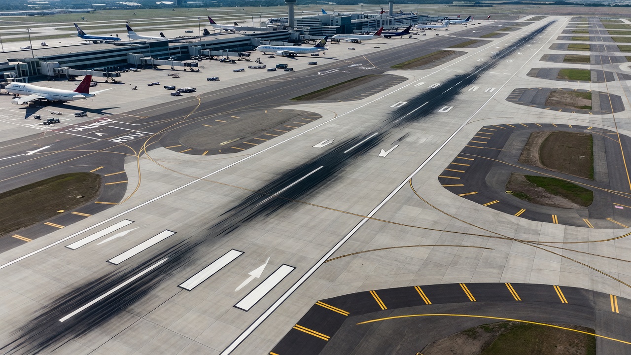
Carbonation in Airport Concrete Pavements
Airport concrete pavements — including runways, taxiways, and aprons — present a unique case for carbonation because they are typically plain (unreinforced) or lightly reinforced pavement slabs with jointed concrete construction. The primary concern is carbonation of dowel bars (load-transfer devices at joints), tie bars, and welded wire fabric reinforcement.
Airport-Specific Factors
Several factors unique to airport pavements influence carbonation risk:
Surface exposure: Pavement surfaces are directly exposed to the atmosphere and subject to continuous CO₂ ingress. The large surface area-to-volume ratio of pavement slabs means that carbonation from the top surface progresses downward toward any reinforcement.
Joint and crack pathways: Transverse and longitudinal contraction joints, as well as random cracks, provide preferential CO₂ ingress routes. Dowel bars placed within joints for load transfer are at particular risk, as the carbonation front can reach these bars through the joint opening in a much shorter time than through intact concrete cover.
Aircraft emissions: Runway zones where aircraft spend time (taxiways near terminals, holding bays) can experience elevated local CO₂ concentrations from jet exhaust, potentially accelerating carbonation in these areas.
Durability requirements:FAA Advisory Circular AC 150/5320-6G (Airport Pavement Design and Evaluation) and ICAO Annex 14 specify concrete quality requirements that inherently control carbonation risk. The FAA P-501 specification for portland cement concrete pavement requires:
Minimum compressive strength: 28–34 MPa (4000–5000 psi) at 28 days
Maximum water-cement ratio: 0.45–0.49 depending on exposure
Concrete cover over reinforcement: 75–100 mm minimum
These requirements produce concrete with low permeability and high carbonation resistance. However, construction variability, improper curing, and long-term surface wear can reduce effective cover depth and accelerate carbonation.
Inspection Considerations
For airport pavement assessment, carbonation depth testing is typically performed on cores extracted at joints (to assess dowel bar environment) and at mid-panel locations (to assess bulk concrete quality). The frequency of testing depends on pavement age, condition rating, and planned rehabilitation. High-quality airport pavements constructed to modern standards typically do not exhibit carbonation reaching reinforcement within the design life (20–40 years), but older pavements and those with construction defects warrant investigation.
Prevention and Mitigation Strategies
Preventing carbonation-induced deterioration requires a multi-layered approach addressing design, materials, construction, and maintenance throughout the structure’s service life.
Design for Carbonation Resistance
Adequate concrete cover over reinforcement is the single most important design parameter for carbonation protection. The Eurocode 2 approach uses exposure classes to define minimum cover depths:
Exposure Class
Environment Description
Minimum Cover (mm)
XC1
Dry or permanently wet
25
XC2
Wet, rarely dry
35
XC3
Moderate humidity (urban)
40
XC4
Cyclic wet-dry
45–55
For critical structures, a performance-based design approach using service life modeling (e.g., DuraCrete, fibi Bulletin 34 models) can be employed to verify that the cover depth statistically exceeds the predicted carbonation depth at the end of the design life with an acceptable probability of failure.
Material Selection
Low water-cement ratio (w/c < 0.45) is essential for producing dense, low-permeability concrete. The use of superplasticizers enables low w/c without compromising workability. Supplementary cementitious materials can improve pore structure refinement, but their effect on carbonation resistance depends on SCM type, replacement level, and curing conditions:
Silica fume (5–10%): Refines pore structure and improves carbonation resistance
Fly ash (15–25%): Beneficial when properly cured; may increase carbonation at >30% replacement
GGBFS (40–60%): Generally similar or slightly reduced carbonation resistance compared to plain Portland cement
Corrosion-resistant reinforcement provides a secondary defense if carbonation does reach the steel:
Epoxy-coated rebar: Physical barrier; vulnerable to coating damage
Stainless steel rebar: Inherent corrosion resistance even in carbonated concrete; higher cost
Fiber-reinforced polymer (FRP) rebar: Non-corrodible; used in aggressive environments
Protective Coatings and Sealers
Surface-applied coatings can significantly reduce CO₂ ingress. The effectiveness is quantified by the CO₂ diffusion resistance factor (μ_CO₂) or the equivalent air layer thickness (sd-value, defined as sd = μ × d, where d is the coating thickness):
Coating Type
sd-value (m)
Effectiveness
Reapplication Interval
Acrylic coating
5–50
Moderate
5–10 years
Polyurethane coating
20–100
High
10–15 years
Epoxy coating
50–500
Very high
10–20 years
Silane/siloxane sealer
1–5
Low (hydrophobic only)
5–8 years
Cementitious render (polymer-modified)
10–50
Moderate
10–20 years
A coating with sd > 50 m is considered highly effective for carbonation protection. The coating must be applied to a sound, clean substrate and maintained through periodic reapplication.
Construction Quality
Proper curing is essential for developing the intended concrete microstructure. Inadequate curing leads to higher surface porosity and reduced carbonation resistance. Minimum curing durations per EN 13670 are:
CEM I (Portland cement): 4–7 days
CEM II (blended cements): 7–14 days
Low-temperature conditions: Extended curing period
Quality control during construction must verify:
Achieved cover depth (survey of 100% of critical areas using cover meters)
Concrete strength (compressive testing at 7 and 28 days)
Concrete permeability (e.g., via air permeability testing per CEN/TS 12390-10)
Maintenance and Monitoring
Regular inspection at intervals of 5–10 years for moderate exposure, or 2–5 years for severe exposure, should include:
Visual inspection for cracking, rust staining, and spalling
Carbonation depth testing (phenolphthalein) on exposed surfaces or cores
Cover depth verification
Half-cell potential mapping where active corrosion is suspected
When the measured carbonation depth approaches 70% of the cover depth, intervention planning should begin. Preventative application of surface coatings at this stage can extend the remaining service life by slowing CO₂ ingress.
Conclusion
Carbonation of concrete is a naturally occurring chemical process driven by the fundamental thermodynamics of cement hydration products in contact with atmospheric CO₂. While carbonation itself does not degrade the concrete matrix — and in fact can increase the mechanical properties of plain concrete through pore filling and strength gain — its effect on the protective passive film of steel reinforcement represents the most significant durability risk for reinforced concrete structures worldwide.
The progressive neutralization of the concrete alkaline reserve, quantified through the measurement of carbonation depth using pH indicator solutions, serves as the essential diagnostic metric for assessing the remaining service life of concrete infrastructure. The square-root-of-time relationship governing carbonation front propagation provides engineers with a powerful predictive tool for scheduling inspections and interventions, provided the carbonation coefficient is accurately determined from representative testing.
Current international standards — particularly RILEM CPC-18R1, EN 14630, and guidance from FAA and ICAO for airport pavements — provide robust frameworks for carbonation assessment and management. The fundamental protection strategy remains the provision of adequate, high-quality concrete cover over reinforcement, supported by dense concrete with low permeability achieved through low water-cement ratios, proper SCM selection, and thorough curing.
As atmospheric CO₂ concentrations continue to rise globally — from pre-industrial levels of ~280 ppm to current levels exceeding 420 ppm — the rate of carbonation-induced deterioration of concrete infrastructure will accelerate. Climate projections indicate further increases to 500–700 ppm by 2100 under current emissions trajectories. Proactive carbonation management through design, material selection, protective systems, and regular monitoring is essential for ensuring the long-term durability and safety of concrete structures in the built environment.
Frequently Asked Questions
Concrete carbonation is a chemical reaction between atmospheric carbon dioxide (CO₂) and the alkaline components of hydrated cement paste, primarily calcium hydroxide (Ca(OH)₂). The reaction produces calcium carbonate (CaCO₃) and reduces the pH of concrete pore water from ~13 down to below 9. This pH reduction is harmful because it destroys the passive oxide film protecting steel reinforcement, initiating corrosion and eventually causing concrete cracking and spalling.
Carbonation depth is typically measured by spraying a freshly fractured or cut concrete surface with a phenolphthalein pH indicator solution. Areas with pH above ~9.5 turn pink/magenta (uncarbonated), while carbonated areas with lower pH remain colorless. The perpendicular distance from the exposed surface to the color change boundary is measured as the carbonation depth. RILEM CPC-18R1 provides the standardized test method. Alternative indicators include thymolphthalein (blue transition at pH 9.3-10.5) and curcumin (yellow transition at pH 7.4-8.6).
Key factors include: (1) Relative humidity of 50-70%, which provides optimal moisture for the reaction without saturating pores; (2) High CO₂ concentration in the environment; (3) Poor concrete quality with high water-cement ratio and high permeability; (4) Low concrete cover over reinforcement; (5) Cracks and construction defects that provide direct pathways for CO₂ ingress; (6) High ambient temperature; (7) Frequent wetting-drying cycles; and (8) Use of certain supplementary cementitious materials at high replacement levels.
Airport concrete pavements (runways, taxiways, aprons) are susceptible to carbonation, particularly on exposed surfaces and along joints and cracks. While the FAA P-501 specification requires minimum concrete cover of 75-100 mm over reinforcement, carbonation depth over decades of service can approach these values in poor-quality concrete. Carbonation reduces surface pH and can initiate corrosion of dowel bars, tie bars, and mesh reinforcement in pavement slabs. Regular carbonation depth testing using phenolphthalein on extracted cores is recommended as part of airport pavement condition inspections per ASTM and FAA guidelines.
Prevention strategies include: (1) Specifying adequate concrete cover depth over reinforcement (typically 30-60 mm minimum depending on exposure); (2) Using low water-cement ratio concrete (w/c < 0.45) for dense, low-permeability microstructure; (3) Proper curing to ensure complete hydration and reduced porosity; (4) Application of surface coatings, sealers, or waterproofing membranes; (5) Use of corrosion-resistant reinforcement (epoxy-coated, stainless steel, or galvanized rebar) in high-risk areas; (6) Quality control during construction to avoid cracks and honeycombing; and (7) Regular condition assessment including carbonation depth monitoring.
Carbonation depth (d) follows a square-root-of-time relationship: d = k × √t, where k is the carbonation coefficient (typically 3-8 mm/√year for normal concrete in urban environments) and t is time in years. This relationship derives from Fick's second law of diffusion, since the carbonation rate is controlled by CO₂ diffusion through the concrete pore structure. Dense concrete with low water-cement ratio can have k values below 2 mm/√year, while poor-quality concrete may exceed 10 mm/√year.
The primary international standard for carbonation depth testing is RILEM CPC-18R1 (2026) — Measurement of hardened concrete carbonation depth using a pH indicator solution. European standard EN 14630:2006 also specifies the phenolphthalein method. Additional standards include ASTM C856 (petrographic examination), ASTM C1580 (carbonate content analysis), and BSI 1881-210. For airport pavements, FAA AC 150/5320-6G and ICAO Annex 14 provide concrete quality requirements that inherently control carbonation risk.
Yes, carbonation can benefit plain (unreinforced) concrete. Calcium carbonate (CaCO₃) fills micro-pores and reduces porosity, increasing both compressive and tensile strength. Carbonation also permanently sequesters CO₂ from the atmosphere, partially offsetting cement production carbon emissions. The calcination of limestone during cement manufacturing releases CO₂, and carbonation reabsorbs approximately 15-57% of those process emissions over concrete's service life and secondary use.
Carbonation-induced corrosion causes uniform, generalized corrosion across the reinforcement surface. Chloride-induced corrosion is highly localized (pitting corrosion) and can initiate even at high pH if chloride concentration exceeds the threshold. Carbonation is dominant in indoor and urban environments; chloride attack is primary in coastal/marine structures and where deicing salts are used. Both mechanisms can act synergistically.
The carbonation front is the boundary region within concrete where pH transitions from low (carbonated zone, pH < 9) to high (uncarbonated zone, pH > 12). It is a zone of partial carbonation typically 1-5 mm wide rather than a perfectly sharp line. The front advances progressively from the exposed surface inward over time following the square-root-of-time law. Its position is identified using pH indicator solutions.
The primary reaction is: Ca(OH)₂ + CO₂ → CaCO₃ + H₂O. Secondary reactions include carbonation of calcium silicate hydrate (C-S-H) gel: C-S-H + CO₂ → CaCO₃ + amorphous silica + H₂O. Ettringite, monosulfate, and calcium aluminate hydrates can also undergo carbonation. The C-S-H carbonation is particularly important because it reduces pH further and can increase porosity.
For w/c 0.40-0.45 (high-quality), k = 2-4 mm/√year, giving 14-28 mm after 50 years. For w/c 0.50-0.55 (moderate), k = 5-8 mm/√year, giving 35-57 mm after 50 years. For w/c > 0.60 (poor), k can exceed 10 mm/√year, reaching >70 mm within 50 years. Blended cement concretes may carbonate faster due to reduced portlandite content.
A 1% phenolphthalein solution in 70/30 ethanol/water is sprayed onto a freshly fractured or saw-cut concrete surface. Where pH exceeds ~9.5, the solution turns bright pink (uncarbonated). Carbonated areas with pH below 9.5 remain colorless. The depth from the exposed surface to the color change boundary is measured. Testing should be performed within 15 minutes of exposing the fresh surface.
Concrete cover serves as the primary barrier against CO₂ diffusion. Standard cover requirements per EN 1992-1-1 range from 25 mm (indoor) to 55 mm (outdoor wet-dry). ACI 318 requires 38-50 mm for weather-exposed concrete. FAA standards specify 75-100 mm for airport pavements. Cover depth must exceed expected carbonation depth at design life plus safety margin.
Higher temperatures increase both CO₂ diffusion rates and reaction kinetics. For every 10°C increase, the carbonation coefficient increases by approximately 30-50%. This has important implications for climate change, as both rising temperatures and increasing CO₂ concentrations will accelerate carbonation-induced deterioration.
Yes. Effective coatings include acrylic, polyurethane, and epoxy systems, as well as silane/siloxane penetrating sealers. Effectiveness is characterized by CO₂ diffusion resistance (sd-value). Coatings with sd > 50 m are considered highly effective. Regular maintenance and reapplication every 5-15 years is required.
Emerging NDT methods include: near-infrared spectroscopy, ground-penetrating radar signal analysis, natural frequency monitoring, endoscopic image analysis of drilled holes, and colorimetric pH sensor strips. However, the phenolphthalein spray test on cores remains the standard for definitive carbonation depth assessment per RILEM CPC-18R1 and EN 14630.
Carbonation can also cause: carbonation shrinkage leading to surface microcracking; reduced alkali content affecting ASR expansion; changes in freeze-thaw resistance; increased surface layer strength; reduced chloride binding capacity releasing bound chlorides; and improved acid resistance from CaCO₃ buffering.
Natural testing exposes specimens to ambient CO₂ (~400 ppm) for months to years, providing realistic rates. Accelerated testing uses elevated CO₂ (1-4%) under controlled conditions to simulate decades in weeks per BS EN 13295 and ISO 1920-12, but results require careful calibration to natural conditions.
Corrosion of reinforcement driven by carbonation and chlorides costs an estimated $150-300 billion annually in repairs. Proactive carbonation management through proper design, quality construction, and regular monitoring can reduce lifecycle costs by 30-50%.
Protect Your Concrete Structures from Carbonation
Ensure long-term durability of your reinforced concrete assets with proper carbonation assessment, monitoring, and prevention strategies. Our experts can help you evaluate carbonation risk and implement effective protective measures for bridges, buildings, and airport infrastructure.
Alkali-Silica Reaction (ASR) is a deleterious chemical reaction between reactive silica in certain aggregates and alkali hydroxides in cement pore solution, pro...
Corrosion of reinforcing steel is the electrochemical deterioration of rebar within concrete, driven by chloride ingress or carbonation destroying the protectiv...
Efflorescence is the white crystalline deposit of water-soluble salts on concrete and masonry surfaces, formed when water migrates through the material and evap...
29 min read
Concrete Defects
Moisture
+3
Cookie Consent We use cookies to enhance your browsing experience and analyze our traffic. See our privacy policy.