Cathodic protection is an electrochemical corrosion mitigation technique that prevents reinforcement corrosion in concrete structures by making the steel the cathode of an electrochemical cell. CP systems are applied to airport pavements, bridge decks, parking structures, and other reinforced concrete infrastructure exposed to deicing chemicals, marine environments, and corrosive agents. Two primary types exist: galvanic (sacrificial anode) CP and impressed current cathodic protection (ICCP).
Definition of Cathodic Protection
Cathodic protection (CP) is an electrochemical corrosion mitigation technique that prevents or stops corrosion of steel reinforcement in concrete structures by making the reinforcing steel the cathode of an electrochemical cell. This is achieved by supplying a protective direct current from an external anode system — either through galvanic coupling to a sacrificial metal or through an impressed current system powered by a transformer/rectifier. CP is the only rehabilitation technique proven to stop corrosion in salt-contaminated concrete regardless of chloride content, as documented by the Federal Highway Administration (FHWA-RD-01-096, 2001).
The fundamental electrochemical principle dates to Sir Humphrey Davy’s work in 1824, who demonstrated that copper in seawater could be protected from corrosion when electrically connected to iron or zinc. Alessandro Volta’s earlier discovery of the voltaic pile (1800) established that electrical current is generated when dissimilar metals with different electro-potentials are connected through an electrolyte. In reinforced concrete, corrosion is an electrochemical process requiring four elements: an anode (where metal oxidation occurs), a cathode (where reduction occurs), an electrolyte (the concrete pore solution), and a metallic path (the rebar itself). In a corroding structure, different areas of the reinforcing steel develop potential differences — some areas become anodic (corroding) and others cathodic (protected). CP overrides these natural corrosion cells by supplying an external current that forces the entire steel reinforcement network to become cathodic relative to an intentionally installed external anode.
Concrete naturally has high alkalinity, with pH values of approximately 12.5 to 14. Under normal conditions, this alkalinity causes a stable passive layer — a thin film of iron oxides and hydroxides — to form on the steel surface, reducing corrosion rates to negligible levels. Two primary mechanisms destroy this passive layer: carbonation (atmospheric CO₂ reacting with pore water to neutralize concrete alkalinity, dropping pH below 11 and eventually below 8, where the passive film becomes unstable) and chloride contamination (chloride ions from deicing salts, seawater, or contaminated aggregates penetrating concrete and breaking down the passive layer locally, initiating pitting corrosion once the [Cl⁻]/[OH⁻] ratio exceeds 0.6 per Hausmann’s research).
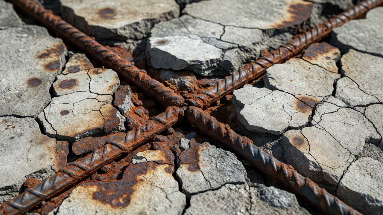
Once initiated, corrosion of steel produces iron oxides (rust) that occupy 2 to 6 times the volume of the original steel. This volumetric expansion generates tensile stresses that cause concrete cracking, spalling, and delamination. Even minute amounts of rust can produce sufficient stress to cause structural damage. CP works by supplying electrons to the steel reinforcement, forcing its potential into a region where the anodic (corrosion) reaction cannot occur. Unlike CP systems for buried pipelines (which aim for the immunity region on the Pourbaix diagram), CP for reinforced concrete aims to restore the steel to the passive region — a more conservative target that avoids the risk of hydrogen embrittlement from over-polarization.
Galvanic (Sacrificial Anode) Cathodic Protection
Galvanic cathodic protection (GCP) — also called sacrificial anode CP — connects the steel reinforcement to a less noble (more electronegative) metal. The potential difference between the two metals creates a natural galvanic cell: the sacrificial metal corrodes preferentially, generating a protective current that flows through the concrete electrolyte to the reinforcing steel. No external power source is required. The anode is consumed over time and must eventually be replaced. GCP is the simplest form of cathodic protection and is frequently used for localized corrosion control.
Anode Materials
Three primary sacrificial anode materials are used in reinforced concrete applications:
Zinc is the most common sacrificial anode material for reinforced concrete. Zinc offers high corrosion efficiency — a high percentage of electrons discharged during corrosion are available to protect the steel — and a relatively low rate of expansion compared to other metals, making it suitable for embedment in concrete. Zinc’s native potential is generally insufficient to cause hydrogen embrittlement, making it suitable for prestressed and post-tensioned concrete. Two activation methods are used: alkali-activated anodes (pH 14–14.5+ environment, using lithium hydroxide saturating a precast mortar matrix) and halide-activated anodes (using chloride, bromide, or other halide salts in direct contact with the zinc surface). Zinc anodes are manufactured in various forms including precast blocks in activated mortar, arc-sprayed (metalized) coatings, adhesive-backed foil, and zinc-impregnated mortar overlays.
Aluminum alloy anodes — particularly Al-Zn-In alloys — are used in certain marine applications where higher driving potentials than zinc are required. Aluminum anodes are common for offshore concrete piles and seawater-exposed structures.
Magnesium provides the highest driving voltage of common sacrificial anodes, generating approximately 0.5 to 1.0 V relative to steel in concrete. However, magnesium is rarely used in concrete due to its high consumption rate, short service life, and risk of hydrogen evolution at the steel surface that can cause hydrogen embrittlement in prestressed tendons.
Current Output and Design Life
Galvanic systems produce relatively low current densities, typically in the range of 0.2 to 2.0 mA/m² of steel surface area, depending on environmental conditions — humidity, temperature, and chloride content significantly influence output. The current is self-limiting and varies with concrete resistivity. Higher resistivity concrete (dry, well-cured) reduces current output; lower resistivity concrete (wet, chloride-contaminated) increases output. Anode current density is typically limited to approximately 10 mA/m² of anode surface for design life calculations. The typical design life of galvanic CP systems is 5 to 20 years depending on anode mass, current output, and environmental aggressivity.
Applications in Reinforcement Protection
GCP is used for several specific applications in reinforced concrete: localized corrosion protection around patch repairs to prevent the incipient anode (halo) effect — where fresh repair mortar is cathodic relative to the adjacent chloride-contaminated concrete, creating a concentrated corrosion cell at the repair boundary; surface-applied galvanic overlays on bridge decks using zinc-impregnated mortar; arc-sprayed zinc coatings on bridge substructures and marine piles; bulk zinc anodes on concrete piles in seawater; and joint protection between new and existing concrete elements.
Impressed Current Cathodic Protection (ICCP)
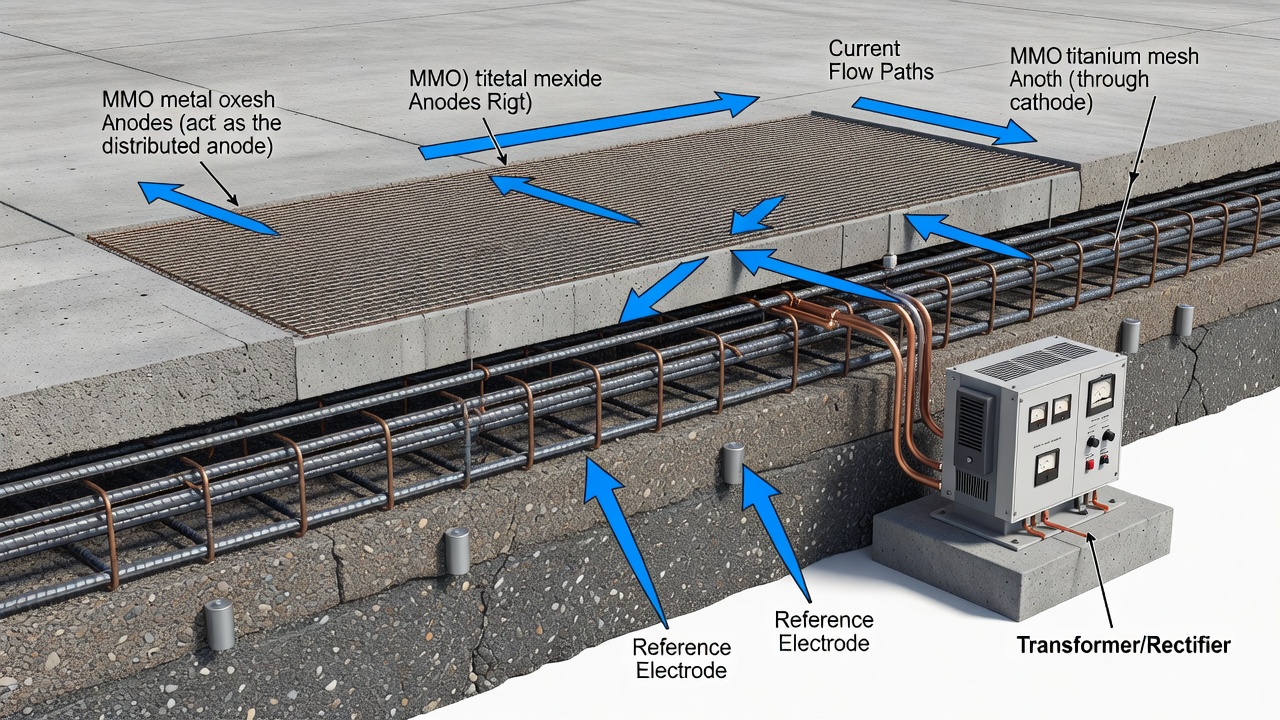
Impressed current cathodic protection (ICCP) uses an external DC power source — typically a transformer/rectifier — to drive current between inert anodes and the reinforcing steel. The negative terminal of the DC power supply is connected to the reinforcing steel, and the positive terminal is connected to the anodes. Current flows from the anode through the concrete electrolyte to the steel surface, polarizing the steel into the passive region. Unlike galvanic systems, ICCP allows precise control of current output and can protect larger structures with higher current demands.
System Components
The transformer/rectifier converts AC mains power to low-voltage DC. Modern units range from 24V to 60V DC output, with amperage ratings from 1A to over 100A depending on system size. Units typically feature constant-current or constant-voltage operation modes, with remote monitoring and control capabilities. Many include data logging, automated polarization testing, and SCADA (Supervisory Control and Data Acquisition) integration.
The anodes are the most critical component. Mixed metal oxide (MMO) coated titanium is the predominant anode type for concrete ICCP. A titanium substrate — manufactured as mesh, ribbon, or expanded grid — is coated with a catalytic mixed metal oxide layer (typically iridium oxide, ruthenium oxide, or tantalum oxide) that is stable in both oxygen and chlorine evolution reactions. MMO titanium anodes have an expected design life exceeding 100 years at full rated current output per NACE TM0294 accelerated testing. Standard products include Elgard™ (Matcor/Vector) and LIDA™ (De Nora). Ribbon anode sizes range from 10 mm to 25.4 mm widths, with current ratings of 2.8 to 7.0 mA per linear meter. Mesh anode systems offer current ratings of 16 to 32 mA/m² of anode surface area.
The reference electrodes are embedded permanent sensors for monitoring steel potential. The most common type for permanent embedment per ISO 12696 is the double-junction Ag/AgCl (silver/silver chloride) electrode with 0.5M KCl filling. MnO₂ (manganese dioxide) electrodes offer an alternative more resistant to the alkaline concrete environment. Portable Cu/CuSO₄ (copper/copper sulfate) electrodes are used for half-cell surveys per ASTM C876 but are not suitable for permanent embedment due to copper ion contamination risk.
Current Density Requirements
Design current densities for ICCP in reinforced concrete are specified per AASHTO, FHWA, ISO 12696, and NACE SP0290 standards:
Parameter
Value
Standard/Source
Initial design current density (depolarized steel)
10–20 mA/m² steel surface
ISO 12696, AS 2832.5
Long-term average current density (polarized steel)
The FHWA maximum limits of 110 mA/m² (continuous) and 220 mA/m² (short-term) for MMO titanium anodes prevent acid generation at the anode-concrete interface, which can cause concrete degradation if exceeded.
Design Life
ICCP systems with MMO titanium anodes are designed for 20 to 40+ years of service, with the anode systems themselves rated for 75 to 100+ years per NACE TM0294 verification. The transformer/rectifier typically has a design life of 20 to 30 years and may require replacement during the system’s service life. The 1993 SHRP S-337 report documented anticipated system lifetimes ranging from 5 to 40 years depending on anode type.
The 100 mV Polarization Criterion
The 100 mV polarization decay criterion, defined in NACE SP0290 (“Impressed Current Cathodic Protection of Reinforcing Steel in Atmospherically Exposed Concrete Structures,” originally published as RP0290) and ISO 12696, is the most widely accepted performance criterion for CP of reinforcing steel in concrete. It requires a minimum of 100 mV of cathodic polarization — either the formation or decay of polarization — measured between the reinforcing steel and a stable reference electrode.
The measurement procedure follows a standardized protocol: the CP system is switched off, and the instant-off potential is recorded immediately (this eliminates the IR drop — the voltage error caused by current flowing through the concrete electrolyte resistance). The depolarization — the potential shift back toward the native/static (corrosion) potential — is then monitored over time, typically 4 to 24 hours. If the steel depolarizes by at least 100 mV within this period, the system is deemed to be providing adequate protection. In saturated or high-moisture concrete (such as seawater pool walls or marine substructures), depolarization rates are very slow, and extended periods of 72+ hours may be required.
The theoretical basis for the 100 mV criterion is that cathodic polarization of at least 100 mV is sufficient to shift corroding steel to the passive region of the Pourbaix diagram, thereby suppressing the anodic corrosion reaction. Alternative criteria per NACE SP0290 include an absolute potential more negative than -1,100 mV vs. Ag/AgCl/0.5M KCl (immunity criterion, rarely applied to concrete due to hydrogen embrittlement risk) and a potential decay of 100 mV measured over a specified period (typically 4 hours).
Half-Cell Potential Measurements
Half-cell potential measurements per ASTM C876 (Standard Test Method for Corrosion Potentials of Uncoated Reinforcing Steel in Concrete) provide a rapid non-destructive assessment of corrosion probability. The measurement uses a portable reference electrode — typically Cu/CuSO₄ — connected to a high-impedance voltmeter, with the other terminal connected to the reinforcing steel. The measured potential is the half-cell potential of the steel relative to the reference electrode.
Potential vs. Cu/CuSO₄
Corrosion Probability
Less negative than -200 mV
>90% probability no corrosion is occurring
-200 mV to -350 mV
Corrosion activity uncertain
More negative than -350 mV
>90% probability corrosion is occurring
Half-cell surveys are used before CP installation to map corrosion risk across a structure and identify areas requiring priority intervention. After CP installation, half-cell measurements verify that the steel potential has been shifted into the protected range. ASTM C876 notes that temperature, concrete moisture content, and the presence of surface coatings can affect readings.
ICAO and FAA Standards for Cathodic Protection
ICAO Annex 14 and Aerodrome Design Manual
ICAO Annex 14, Volume I (8th Edition, July 2018, incorporating amendments through Amendment 14) establishes international Standards and Recommended Practices (SARPs) for aerodrome design and operations. Chapter 10 — Aerodrome Maintenance addresses pavements, stating that the surface of pavements shall be maintained in a condition to prevent the formation of harmful irregularities. While Annex 14 does not explicitly mandate cathodic protection, it establishes the framework requiring that aerodrome pavements maintain structural integrity throughout their service life.
The ICAO Aerodrome Design Manual (Doc 9157), Part 3 — Pavements provides additional guidance on infrastructure protection. The manual references the need for corrosion protection of reinforcement, noting that where pavements are exposed to deicing chemicals, sea spray, or other corrosive agents, additional protective measures for reinforcing steel should be considered. Annex 14, Section 3.13 — Aprons and Section 3.15 — De-icing/Anti-icing Facilities are particularly relevant, as these areas are subject to high chloride exposure from deicing fluids. The recommended practices imply that corrosion protection measures, including CP where appropriate, should be applied to reinforced concrete in these zones.
FAA Advisory Circulars
FAA Advisory Circular AC 150/5370-10H (Standards for Specifying Construction of Airports) provides standard specifications for materials and methods used in airport construction. The document includes specifications for Portland Cement Concrete Pavement (P-501) and structural concrete (P-510) with measures designed to limit corrosion risk — including maximum water-cement ratio (0.40 to 0.45), minimum cement content (335 to 365 kg/m³), air entrainment (5 to 7 percent), and minimum concrete cover over reinforcement (50 to 75 mm depending on exposure). For projects in corrosive environments — marine coastal areas and deicing chemical exposure zones — supplemental specifications incorporating CP are anticipated. The AC references FAA Engineering Brief No. 70 regarding test protocols and decision trees for construction quality.
FAA Advisory Circular AC 150/5320-6G (Airport Pavement Design and Evaluation) provides procedures for the design and evaluation of airport pavements. It covers rigid pavement design using FAARFIELD 2.0 and addresses pavement deterioration mechanisms, including reinforcement corrosion. The document recognizes that chloride-induced corrosion from deicing chemicals is a significant durability concern for airfield rigid pavements. The pavement design methodology incorporates service life considerations that implicitly require corrosion protection measures for long-term performance.
Why Aviation Infrastructure Requires CP
Five factors drive the application of CP in aviation infrastructure: deicing chemical exposure — aircraft deicing fluids (glycol-based) and pavement anti-icing chemicals (potassium acetate, sodium acetate, calcium magnesium acetate) contain aggressive constituents that penetrate concrete and attack reinforcing steel; jet blast and thermal cycling — jet exhaust creates thermal stresses that accelerate concrete deterioration and crack formation, providing pathways for chlorides; marine/coastal locations — many major airports are located in coastal areas with salt-laden air and sea spray; heavy dynamic loading — aircraft traffic induces flexural stresses that propagate microcracks, increasing permeability; and runway grooving and saw-cut joints — creating direct pathways for water and chloride ingress to reinforcement.
Chloride Content and Corrosion Thresholds
The initiation of corrosion in reinforced concrete is governed by the chloride content at the reinforcement level. Per the SHRP S-337 report (1993) and multiple international standards, corrosion typically initiates when chloride content exceeds 0.6 to 1.4 lb Cl⁻ per cubic yard of concrete (0.36 to 0.83 kg/m³), equivalent to approximately 0.06 to 0.40 percent of cement mass. For bridge structures, the critical value is reported as 1.0 to 1.4 lb Cl⁻ per cubic yard (0.6 to 0.8 kg/m³) above which corrosion in concrete can occur. The ratio [Cl⁻]/[OH⁻] greater than 0.6 is a commonly cited threshold for depassivation per Hausmann’s research.
A key advantage of CP is that it remains effective regardless of chloride content — it does not require removal of chloride-contaminated concrete. The CP system supplies sufficient cathodic current to overcome the aggressive environment and maintain the steel in the passive state, even when chloride levels far exceed the corrosion initiation threshold.
Installation Methods for Cathodic Protection
Retrofit Installation on Existing Structures
Installing CP on existing reinforced concrete structures follows a systematic process comprising four phases:
Phase 1 — Condition Assessment includes visual survey (documenting cracking, spalling, delamination, and rust staining); delamination survey using chain drag or infrared thermography; half-cell potential mapping per ASTM C876 to identify actively corroding areas; chloride ion content analysis by titration at incremental depths from the surface to the reinforcement level; concrete cover depth measurement using a cover meter; and electrical continuity testing of the reinforcing steel cage to confirm that all reinforcement elements are electrically connected.
Phase 2 — Concrete Repairs must be completed before CP installation. All delaminated, spalled, or chloride-contaminated concrete is removed — not to eliminate all chlorides (which the CP system can manage), but to restore structural integrity and ensure uniform electrolyte conductivity. Partial-depth breakout exposes reinforcement for cleaning where section loss exceeds 10 to 20 percent. Steel is cleaned by sandblasting or water-jetting to remove corrosion products. Patch repairs use compatible repair mortars. Critically, the incipient anode (halo effect) — where fresh repair mortar is cathodic to the adjacent chloride-contaminated concrete — must be addressed by extending the CP system over the entire structure rather than relying on localized protection.
Phase 3 — Anode Installation varies by CP type. For ICCP, three primary methods exist: titanium MMO mesh overlay system — mesh is attached to the prepared concrete surface using nylon fasteners, then covered with a minimum 40 to 50 mm of shotcrete or Portland cement concrete overlay (used for bridge decks, parking decks, and horizontal surfaces); titanium MMO ribbon slot system — slots 6 to 10 mm wide by 20 to 25 mm deep are cut at 150 to 300 mm spacing, ribbon anodes are placed and backfilled with conductive cementitious grout (used for vertical surfaces, soffits, and areas where overlay weight is a concern); and discrete (point) anodes — MMO-coated titanium tubes or rods installed in drilled holes for localized protection of columns, beam ends, and repair patches. For GCP, installation methods include surface-mounted zinc anodes in activated mortar, arc-sprayed zinc coatings (0.2 to 0.5 mm thickness), and adhesive-backed zinc foil.
Phase 4 — Connections and Commissioning involves making negative (cathodic) connections to the reinforcing steel at multiple locations, embedding reference electrodes at representative locations (minimum one per control zone), installing and programming the rectifier, and verifying system performance through the 100 mV depolarization test.
New Construction Installation
For new construction, CP can be installed proactively at significantly lower cost than retrofit. Anode mesh or ribbon is placed in the formwork before concrete placement, tied to the rebar cage using non-conductive spacers to maintain a standoff distance of 25 to 50 mm from the steel. Ribbon anodes can be clipped directly to rebar with plastic clips. Conduits are provided for future wiring and reference electrode replacement. The power supply location is coordinated during design. This approach is cost-effective because it avoids the high cost of concrete removal and repair incurred in retrofit installations, and can extend service life indefinitely when combined with quality concrete.
Monitoring and Maintenance of CP Systems
Reference Electrodes
Reference electrodes are the primary monitoring instruments for CP systems. Ag/AgCl (silver/silver chloride) electrodes are the most commonly used type for permanent embedment in concrete per ISO 12696. Double-junction designs minimize chloride contamination of the concrete. Ag/AgCl electrodes offer stable long-term performance, though drift can occur over 10+ years. Cu/CuSO₄ (copper/copper sulfate) electrodes are the standard for portable half-cell surveys per ASTM C876, with typical potential ranges of -350 to -1,100 mV for CP-protected steel. Cu/CuSO₄ electrodes are not suitable for permanent embedment due to copper ion contamination risk. MnO₂ (manganese dioxide) electrodes offer an alternative more resistant to the alkaline concrete environment. Activated titanium (Ti/MMO) pseudo-reference electrodes offer lower cost but less stability than Ag/AgCl.
Monitoring Schedule
Per NACE SP0290, the monitoring schedule for CP systems follows defined intervals. Monthly activities include logging system current, voltage, and operating time, and visual inspection of the rectifier cabinet and cable connections. Quarterly activities include recording reference electrode potentials and adjusting system parameters if needed. Annual activities include a full performance assessment — the 100 mV polarization decay test, IR-drop corrected potential measurements, and comprehensive system diagnostics. At system commissioning, baseline polarization tests are conducted, all reference electrodes are verified, and operating parameters are established and documented.
Current Output Adjustment
Per NACE SP0290, the CP system current should be adjusted to the minimum level that consistently achieves the 100 mV polarization criterion. Over-polarization wastes energy and introduces risks: hydrogen embrittlement of high-strength steel in prestressed or post-tensioned concrete (cathodic hydrogen generation at potentials more negative than -1,100 mV vs. Cu/CuSO₄); acid generation at the anode-concrete interface from oxygen evolution; alkali-aggregate reaction (AAR) acceleration from increased ion migration; and loss of bond between steel and concrete from excessive cathodic reactions.
System Troubleshooting
Common CP system issues include: current not achieving protection criteria — increase current within anode density limits, check for electrical discontinuity in the steel circuit, and verify reference electrode function; rapid depolarization — indicates inadequate polarization, requiring increased current output; slow depolarization in saturated concrete — extend test period beyond 24 to 72 hours as high moisture content slows ionic movement; rectifier failure — check AC power supply, fuses, and rectifier diodes (remote alarms recommended); and reference electrode drift — replace or cross-reference with a portable electrode.
Applications in Aviation Infrastructure
Runway and Taxiway Rigid Pavements
Runway and taxiway rigid pavements are constructed of Portland cement concrete (PCC), typically reinforced with steel dowels, tie bars, and temperature steel. These pavements are exposed to deicing and anti-icing chemicals — potassium acetate (KAc), sodium acetate (NaAc), and sodium chloride (NaCl) — applied directly to pavement surfaces that penetrate through joints, cracks, and grooved surfaces. Jet blast from aircraft engines causes thermal gradients that accelerate concrete deterioration. Dynamic loading from heavy aircraft (Code E and F categories exceeding 560,000 kg MTOW, such as the Boeing 777 and Airbus A380) induces flexural stresses that propagate microcracks.
CP for runway pavements is typically installed as a conductive overlay system — MMO mesh embedded in a concrete overlay — during major rehabilitation projects. Given the critical nature of runway surfaces, overlay thickness (typically 100 to 200 mm), surface friction characteristics, and grooving compatibility must be carefully considered. The overlay requires FAA approval per AC 150/5370-10H and must satisfy runway surface friction requirements per ICAO Annex 14.
Bridge Decks on Airport Access Roads
Airport access road bridges and elevated roadways are exposed to the same deicing chemicals as public highways. ICCP with titanium mesh in a concrete overlay is the standard approach, with design parameters per FHWA and AASHTO guidelines. FHWA field evaluations (FHWA-RD-01-096) have demonstrated 20+ years of effective CP operation on bridge decks, with operating current densities as low as 1.84 to 2.2 mA/m² of concrete surface area achieving successful polarization.
Parking Structures
Airport parking garages are among the most corrosion-prone structures in aviation infrastructure due to continual chloride exposure from vehicles tracking deicing chemicals from apron areas, poor ventilation that traps moisture and chlorides, and deicing spray drift from adjacent aircraft operations. ICCP with MMO titanium ribbon anodes installed in slots (for parking decks) or discrete anodes (for columns and beams) is widely used. Numerous major airport parking structures have been successfully retrofitted with CP systems extending service life by 20 to 30+ years.
Terminal Building Foundations
Below-grade concrete elements — foundations, retaining walls, pile caps — in airports are vulnerable to chloride-laden groundwater in coastal areas. Galvanic CP with bulk zinc anodes or impressed current with deep anode ground beds provides protection. The ICAO Aerodrome Design Manual recommends that foundation corrosion protection be considered for structures in aggressive ground conditions.
Jet Blast Areas
Reinforced concrete areas directly behind aircraft engine exhaust — runway blast pads and taxiway holding areas — experience extreme thermal cycling and mechanical erosion. CP is challenging in these zones due to anode proximity to high-temperature surfaces, but MMO titanium anodes embedded at sufficient depth (50+ mm) have been successfully applied. The FAA requires that any CP system installed in jet blast areas not create FOD (foreign object debris) hazards from anode materials or concrete cover.
Cathodic protection for reinforced concrete in aviation infrastructure is governed by multiple international and national standards. The primary documents include: NACE SP0290 — Impressed Current Cathodic Protection of Reinforcing Steel in Atmospherically Exposed Concrete Structures; ISO 12696 — Cathodic Protection of Steel in Concrete; ASTM C876 — Standard Test Method for Corrosion Potentials of Uncoated Reinforcing Steel in Concrete; ASTM C1583 — Standard Test Method for Tensile Strength of Concrete Surfaces and the Bond Strength or Tensile Strength of Concrete Repair and Overlay Materials by Direct Tension (Pull-off Method); FHWA-RD-01-096 — Cathodic Protection of Reinforced Concrete Bridge Elements; SHRP S-337 — Cathodic Protection of Reinforced Concrete Bridge Components; AASHTO — Standard Specifications for Highway Bridges; ICAO Annex 14, Volume I — Aerodrome Design and Operations; ICAO Aerodrome Design Manual (Doc 9157), Part 3 — Pavements; FAA AC 150/5370-10H — Standards for Specifying Construction of Airports; FAA AC 150/5320-6G — Airport Pavement Design and Evaluation; and FAA Engineering Brief No. 70.
The selection of the appropriate CP system type depends on structure size, corrosion severity, environmental conditions, design life requirements, budget, and access constraints. A properly designed, installed, and maintained cathodic protection system can extend the service life of reinforced concrete structures in aviation infrastructure by 20 to 40+ years, making it one of the most cost-effective corrosion management strategies available.
Frequently Asked Questions
Cathodic protection (CP) is an electrochemical technique that prevents corrosion of steel reinforcement in concrete by making the reinforcing steel the cathode of an electrochemical cell. In a natural corrosion cell, anodic areas on the steel surface undergo oxidation (metal loss), producing rust that expands and cracks the concrete. CP overrides these natural corrosion cells by supplying an external DC current that forces the entire steel reinforcement network to function as a cathode relative to intentionally installed external anodes. The protective current supplies electrons to the steel, shifting its electrochemical potential into the passive region where the anodic corrosion reaction cannot occur. The fundamental principle was discovered by Sir Humphrey Davy in 1824, but the first field application to reinforced concrete bridge structures occurred in 1959 in the San Francisco Bay area. Per the FHWA, CP is 'the only rehabilitation technique proven to stop corrosion in salt-contaminated bridge decks regardless of the chloride content of the concrete' (FHWA-RD-01-096, 2001).
The two primary types of cathodic protection for reinforced concrete are galvanic (sacrificial anode) CP and impressed current cathodic protection (ICCP). Galvanic CP (GCP) connects the steel reinforcement to a less noble metal — typically zinc, aluminum, or magnesium — which corrodes preferentially, generating a protective current through the concrete electrolyte. GCP requires no external power source and is self-limiting. It produces current densities of 0.2–2.0 mA/m² of steel surface, with typical design lives of 5–20 years depending on anode mass. GCP is used for localized protection around patch repairs, incipient anode prevention, and marine substructures. ICCP uses an external DC power source (transformer/rectifier) to drive current between inert anodes — typically mixed metal oxide (MMO) coated titanium — and the reinforcing steel. ICCP allows precise control of current output (5–20 mA/m² of steel surface, up to 50 mA/m² in aggressive environments), can protect larger structures, and has design lives of 20–40+ years with anode systems rated for 75–100+ years. ICCP requires regular monitoring and adjustment.
ICAO Annex 14, Volume I (8th Edition, July 2018), Chapter 10 on Aerodrome Maintenance requires airport pavements to be maintained in a condition that prevents the formation of harmful irregularities and mandates structural integrity throughout the service life. While Annex 14 does not explicitly mandate cathodic protection, the Aerodrome Design Manual (Doc 9157) references the need for corrosion protection of reinforcement where pavements are exposed to deicing chemicals, sea spray, or other corrosive agents. Section 3.13 (Aprons) and Section 3.15 (De-icing/Anti-icing Facilities) are particularly relevant, as these areas face high chloride exposure. FAA Advisory Circular AC 150/5370-10H provides standard specifications for airport construction including Portland Cement Concrete Pavement (P-501) with measures to limit corrosion risk. AC 150/5320-6G on Airport Pavement Design and Evaluation recognizes chloride-induced corrosion from deicing chemicals as a significant durability concern. FAA Engineering Brief No. 70 provides test protocols and decision trees for construction quality related to corrosion protection.
The 100 mV polarization decay criterion, defined in NACE SP0290 and ISO 12696, is the most widely accepted performance criterion for cathodic protection of reinforcing steel in concrete. It requires a minimum of 100 mV of cathodic polarization shift — either the formation or decay of polarization — measured between the reinforcing steel and a stable reference electrode. The measurement procedure involves switching off the CP system and recording the instant-off potential (eliminating IR drop errors). The depolarization (potential shift toward the native/static potential) is then monitored over time — typically 4 to 24 hours. If the steel depolarizes by at least 100 mV within this period, the system is deemed to be providing adequate protection. In saturated or high-moisture concrete, depolarization rates are very slow, and extended periods (72+ hours) may be required. The theoretical basis is that cathodic polarization of at least 100 mV is sufficient to shift corroding steel to the passive region of the Pourbaix diagram, suppressing the anodic corrosion reaction.
Installing CP on existing structures follows a systematic four-phase process. Phase 1 — Condition Assessment: visual survey, delamination survey (chain drag or infrared thermography), half-cell potential mapping per ASTM C876, chloride ion content analysis at incremental depths, concrete cover measurement, and electrical continuity testing of the reinforcement cage. Phase 2 — Concrete Repairs: all delaminated, spalled, or chloride-contaminated concrete is removed to restore structural integrity and ensure uniform electrolyte conductivity. Steel is cleaned where section loss exceeds 10–20%, and compatible repair mortars are applied. Phase 3 — Anode Installation: for ICCP, titanium MMO mesh is attached to the prepared surface and covered with a minimum 40–50 mm concrete overlay (horizontal surfaces), or MMO ribbon is placed in cut slots (vertical surfaces/soffits). Discrete anodes are used for localized protection. For GCP, zinc anodes are installed in cored holes or zinc is arc-sprayed onto the surface. Phase 4 — Connections and Commissioning: negative connections to reinforcing steel, reference electrode embedment, rectifier installation and programming, and verification via the 100 mV depolarization test.
Design current densities for cathodic protection of reinforced concrete are specified per AASHTO, FHWA, ISO 12696, and NACE SP0290 standards. For ICCP systems, the initial design current density for depolarized steel is 10–20 mA/m² of steel surface area. As the steel polarizes over time, the long-term average current density typically drops to 2–10 mA/m². Many designers adopt 20 mA/m² as a conservative upper bound for typical structures. In aggressive environments with high chloride content, high moisture, and elevated temperatures, current densities up to 50 mA/m² may be required per AS 2832.5 commentary. The FHWA maximum continuous anode-to-concrete current density limit is 110 mA/m² of MMO titanium anode surface, with short-term limits up to 220 mA/m². These limits prevent acid generation at the anode-concrete interface. For galvanic CP systems, typical current output ranges from 0.2–2.0 mA/m² of steel surface, self-limited by the concrete resistivity. FHWA field evaluations have reported successful polarization exceeding 100 mV at operating current densities as low as 1.84–2.2 mA/m² of concrete surface area on bridge decks.
CP monitoring employs embedded reference electrodes — typically Ag/AgCl (silver/silver chloride) for permanent embedment per ISO 12696, or MnO₂ (manganese dioxide) as an alternative. Portable Cu/CuSO₄ (copper/copper sulfate) electrodes are used for half-cell surveys per ASTM C876. Per NACE SP0290, the monitoring schedule includes: monthly logging of system current, voltage, and operating time with visual inspection of the rectifier and connections; quarterly recording of reference electrode potentials with system adjustment if needed; and annual full performance assessment including the 100 mV polarization decay test and IR-drop corrected potential measurements. System current should be adjusted to the minimum level that consistently achieves the 100 mV criterion to avoid over-polarization risks including hydrogen embrittlement of high-strength steel (prestressed tendons), acid generation at the anode-concrete interface, alkali-aggregate reaction acceleration, and loss of bond between steel and concrete. Common troubleshooting issues include inadequate current (increase within anode density limits), rapid depolarization (inadequate polarization), slow depolarization in saturated concrete (extend test period), and reference electrode drift (cross-reference with portable electrode).
Cathodic protection is applied to multiple reinforced concrete elements in aviation infrastructure. Airport runway and taxiway rigid pavements — constructed of PCC with steel dowels, tie bars, and temperature steel — are exposed to deicing/anti-icing chemicals (potassium acetate, sodium acetate, sodium chloride) that penetrate through joints, cracks, and grooved surfaces. CP is typically installed as a conductive overlay system (MMO mesh in concrete overlay) during major rehabilitation. Bridge decks on airport access roads are exposed to highway deicing chemicals and use standard ICCP with titanium mesh in concrete overlay per FHWA/AASHTO guidelines. Airport parking structures are among the most corrosion-prone structures due to continual chloride exposure from vehicles tracking deicing chemicals, poor ventilation, and deicing spray drift from apron areas — ICCP with MMO ribbon anodes in slots or discrete anodes for columns is widely used. Terminal building foundations in coastal areas use galvanic CP with bulk zinc anodes or impressed current with deep anode ground beds. Jet blast areas behind aircraft engine exhaust experience extreme thermal cycling and mechanical erosion — MMO titanium anodes embedded at sufficient depth (50+ mm) have been successfully applied.
Protect Your Airport Infrastructure from Corrosion
TarmacView provides AI-powered infrastructure inspection solutions that identify corrosion risk areas in reinforced concrete pavements and structures. Our technology helps airport operators prioritize cathodic protection interventions and verify CP system performance. Schedule a demonstration to see how our tools enhance your corrosion management program.
Impressed Current Cathodic Protection (ICCP) for Concrete
Impressed Current Cathodic Protection (ICCP) applies a small DC current from an external power source through inert anodes to reinforcing steel, forcing the ste...