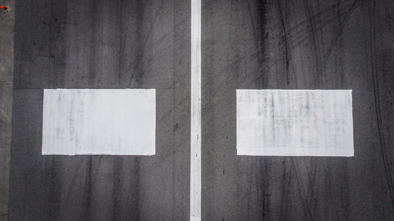
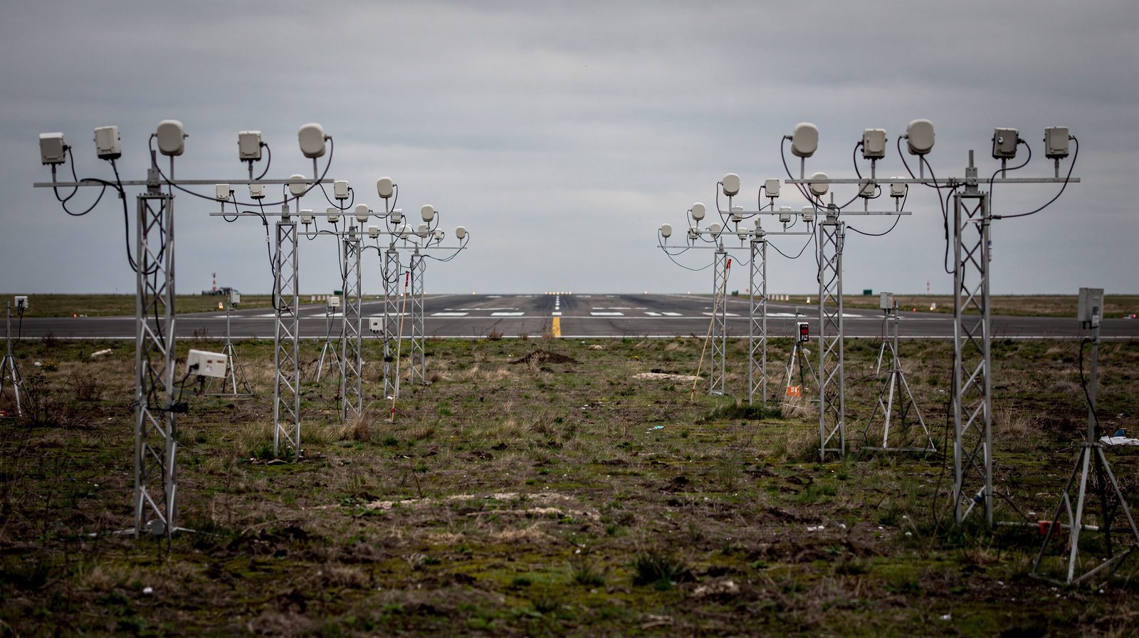
What is a Centerline Marking?
Centerline Marking, Definition and Purpose
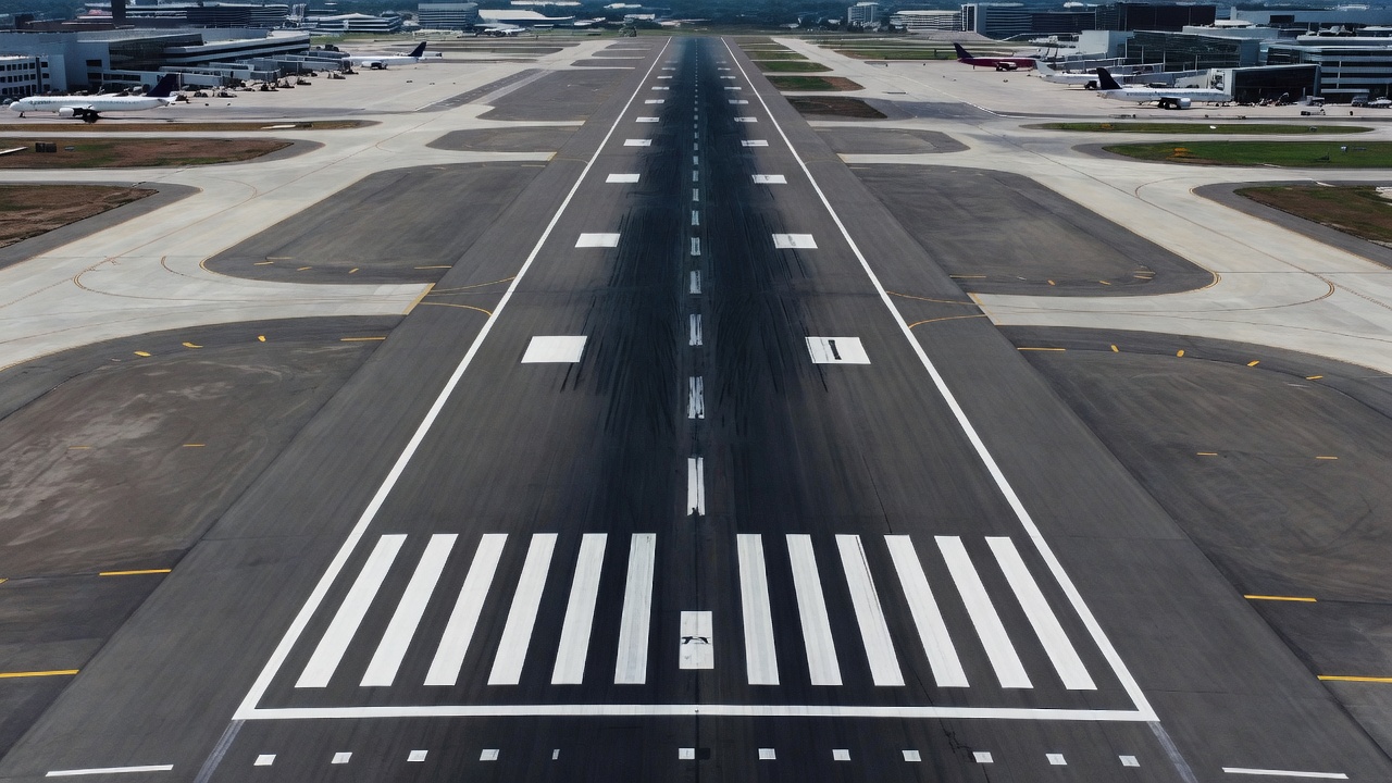
A centerline marking is a painted visual aid located along the geometric center of a runway or taxiway pavement surface at an aerodrome. It is one of the most fundamental and critical visual cues provided to pilots for safe aircraft operations. The marking serves as the primary longitudinal reference that enables pilots to maintain correct positioning on the pavement surface during all phases of flight, takeoff roll, landing rollout, and taxiing.
The operational significance of centerline markings extends across all flight visibility conditions. During daytime visual meteorological conditions (VMC), the centerline provides a continuous tracking reference that is especially important during crosswind operations when the pilot must compensate for drift while maintaining alignment with the runway axis. During night operations, centerline markings are illuminated by aircraft landing lights, providing the only constant visual reference for longitudinal positioning. In reduced visibility conditions such as fog, rain, or haze, the centerline marking, particularly when enhanced with retroreflective materials, may be the only visual cue available to confirm runway or taxiway alignment.
Centerline markings are standardized at the international level through the International Civil Aviation Organization (ICAO) Annex 14, Volume I, Aerodromes, specifically Chapter 5 covering Visual Aids for Navigation. National aviation authorities translate these international standards into their own regulatory frameworks. In the United States, the Federal Aviation Administration (FAA) provides detailed specifications in Advisory Circular 150/5340-1M, Standards for Airport Markings and the Aeronautical Information Manual (AIM) Chapter 2, Section 3. In Europe, the European Union Aviation Safety Agency (EASA) specifies requirements through CS-ADR-DSN (Certification Specifications for Aerodrome Design).
The fundamental color distinction between runway and taxiway centerline markings is one of the most important concepts in airfield marking design. Runway centerline markings are always white, white has been selected as the international standard because it provides maximum contrast against dark asphalt or concrete pavement surfaces, can be easily distinguished from other markings, and retroreflective white materials provide excellent night visibility. Taxiway centerline markings are always yellow, yellow was selected to clearly distinguish taxiway guidance from runway guidance, preventing pilots from mistaking a taxiway for a runway during low-visibility operations. This color coding is universal across all ICAO member states and is considered a fundamental aviation safety convention.
Runway Centerline Marking Configuration
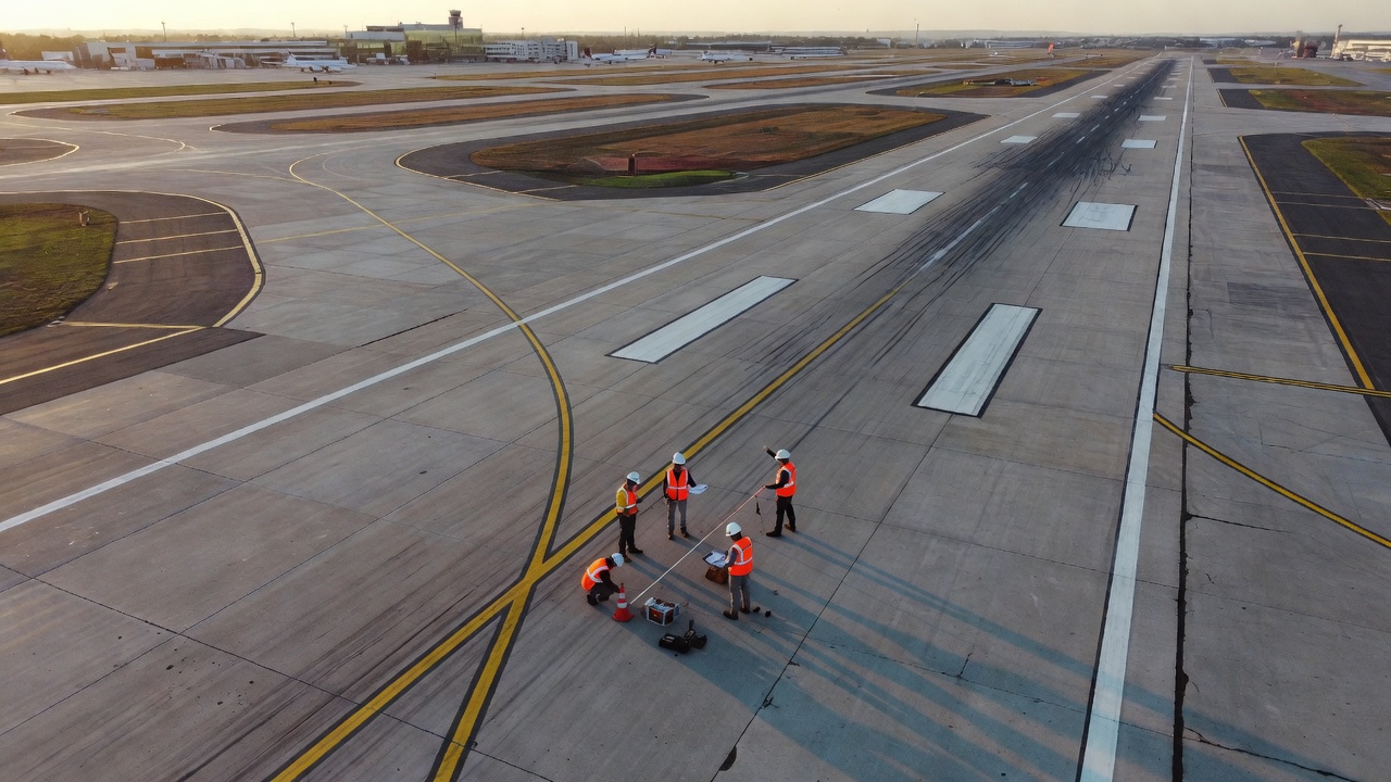
A runway centerline marking is not a continuous solid line. It consists of a line of uniformly spaced stripes and gaps that extends the full length of the runway between the runway designation markings, except where interrupted by runway holding positions or other markings. The use of stripes and gaps, rather than a continuous line, serves a specific operational purpose: as an aircraft accelerates during takeoff or decelerates during landing, the increasing or decreasing frequency at which stripes pass beneath the aircraft provides an indirect speed cue. When the pilot perceives the stripes passing at an appropriate rate, it offers supplemental confirmation of the aircraft’s speed relative to the runway length remaining.
The stripe and gap configuration is defined by ICAO Annex 14 with specific dimensional requirements that vary by runway category. The total length of one stripe plus one gap, referred to as one full cycle, must be not less than 50 m nor more than 75 m. Within each cycle, the length of each individual stripe must be at least equal to the length of the gap, or 30 m, whichever is greater. This ensures that the stripe is always at least as prominent as the gap and that the marking remains clearly visible even at high takeoff and landing speeds.
The stripe and gap dimensions are optimized for the visual perception capabilities of pilots at the critical speeds encountered during takeoff and landing. At a typical takeoff speed of 140 knots (72 m/s) for a medium-sized commercial jet, a 50 m stripe passes beneath the aircraft in approximately 0.7 seconds, long enough to be clearly perceived but not so long that the pilot loses the smooth tracking reference. The gap provides a brief pause in the stripe pattern that the pilot’s peripheral vision processes as continuous information, effectively creating a perceptual illusion of a continuous line while providing the speed cue benefit.
The width of the centerline stripes is graduated according to the precision category of the runway approach. For precision approach runways Category II and III, the highest precision categories used for automatic landing operations, the stripe width must be not less than 0.90 m. These runways support the lowest visibility landing minima (down to 50 m RVR for Category IIIc), and the wider stripe provides the maximum visual cue for automatic flight control systems and pilots transitioning from instrument to visual references at extremely low altitudes. For non-precision approach runways with a code number of 3 or 4 (runway length of 1200 m or greater) and precision approach Category I runways, the minimum stripe width is 0.45 m. For non-precision approach runways with code number 1 or 2 (runway length less than 1200 m) and non-instrument runways, the minimum stripe width is 0.30 m.
| Runway Category | Minimum Stripe Width (ICAO) | FAA Equivalent Width | Maximum Cycle Length |
|---|---|---|---|
| Precision Cat II/III | 0.90 m | 36 inches | 75 m |
| Precision Cat I, Non-Precision (Code 3/4) | 0.45 m | 18-24 inches | 75 m |
| Non-Precision (Code 1/2), Non-Instrument | 0.30 m | 12-18 inches | 75 m |
The FAA Advisory Circular 150/5340-1M provides dimensional specifications that are consistent with ICAO but expressed in imperial units. For precision instrument runways, FAA requires centerline stripe widths of 36 inches (0.91 m). For non-precision instrument runways, the width is 18 to 24 inches (0.46 to 0.61 m). For visual runways, the width is 12 to 18 inches (0.30 to 0.46 m). The FAA specifies that the stripe and gap pattern shall use a 100-foot stripe length and 100-foot gap length for a total cycle of 200 feet (61 m) on precision runways, or a 75-foot stripe and 75-foot gap for a 150-foot cycle (46 m) on visual runways.
The runway centerline marking begins at the runway designation marking at each end of the runway and extends continuously to the opposite designation marking. At runway holding positions intersecting the runway, the centerline may be interrupted to accommodate the holding position marking. The centerline is always centered on the runway, equidistant from both runway edges, and all other runway markings (threshold markings, aiming point markings, and touchdown zone markings) are symmetrically arranged about the centerline.
Taxiway Centerline Marking Configuration
A taxiway centerline marking is fundamentally different from a runway centerline marking in both visual appearance and operational function. While runway centerlines provide guidance at high speeds (50 to 170 knots), taxiway centerlines guide aircraft at low taxi speeds (typically 10 to 30 knots) in a complex network of intersecting paths, often in close proximity to other aircraft, vehicles, buildings, and obstacles.
The standard taxiway centerline marking is a continuous solid yellow line, with no gaps or pattern. The line width ranges from 15 cm (6 inches) to 30 cm (12 inches) depending on the taxiway classification and airport specifications. ICAO Annex 14 specifies that the taxiway centerline marking shall be at least 15 cm wide. The FAA requires a minimum of 6 inches (15 cm) for standard taxiways and recommends 12 inches (30 cm) for high-speed exit taxiways and taxiways serving the largest aircraft (Airplane Design Group V and VI, including Boeing 747, 777, and Airbus A380).
The continuous nature of the taxiway centerline is operationally necessary. Taxiway centerlines provide nosewheel guidance, the pilot is trained to keep the aircraft’s nosewheel aligned with the centerline stripe. A continuous line provides uninterrupted tracking reference, which is especially critical during low-visibility taxi operations (below 400 m RVR) and at complex intersections where multiple taxiways converge. The absence of stripes and gaps eliminates ambiguity at intersections, there is only one continuous yellow line to follow, regardless of the intersecting taxiway pattern.
Taxiway centerline markings are offset from runway centerline markings at runway-taxiway intersections. At these intersections, the taxiway centerline curves to join the runway centerline at a specified angle and radius. The taxiway centerline lead-in to the runway is designed with specific geometry to ensure the aircraft aligns with the runway centerline before reaching the runway threshold. The FAA requires that the taxiway centerline intersect the runway centerline at a 45-degree to 90-degree angle depending on the taxiway type (right-angle, acute-angle, or rapid exit). For rapid exit taxiways (RET) , the intersection angle is typically 30 degrees, and the taxiway centerline is designed with a spiral or compound curve that guides aircraft to a smooth exit at speeds up to 60 knots.
The taxiway centerline is continuous through intersections except where it must give way to a runway-holding position marking. At intersections where two taxiways cross, one centerline typically continues while the other is interrupted. The preferred direction at intersections is established by the airport’s operational pattern, the primary taxi route is indicated by an unbroken centerline, and the intersecting taxiway has a broken or interrupted centerline approaching the intersection. ICAO Annex 14 specifies that at taxiway intersections, the marking of the more important taxiway should be continuous, and the centerline of the intersecting taxiway should be interrupted.
| Element | Taxiway Centerline | Runway Centerline |
|---|---|---|
| Color | Yellow | White |
| Pattern | Continuous solid line | Stripes and gaps |
| Width range | 15 cm to 30 cm | 30 cm to 90 cm |
| Cycle length | Not applicable | 50 m to 75 m stripe + gap |
| Primary function | Nosewheel taxi guidance | Longitudinal alignment at speed |
Enhanced Taxiway Centerline, Runway Incursion Prevention
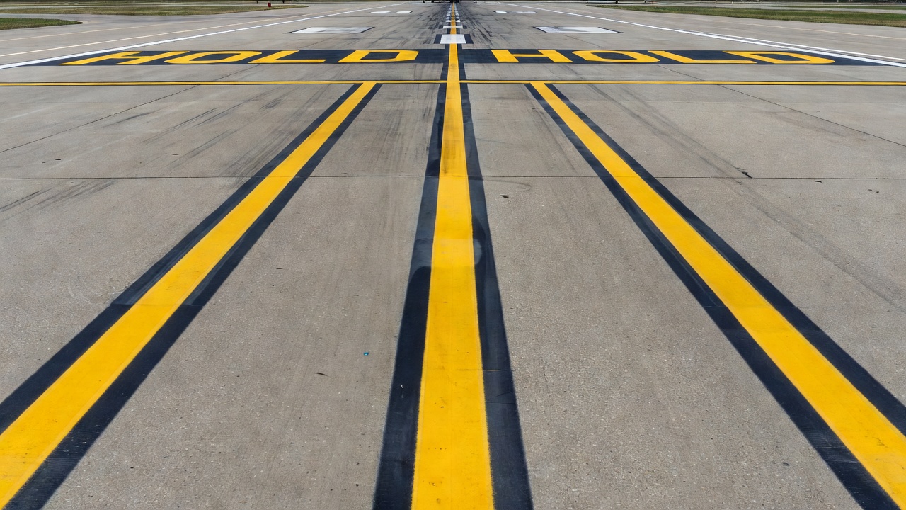
The Enhanced Taxiway Centerline (ETCL) is specifically designed as a runway incursion prevention measure. It was developed in response to the increasing incidence of runway incursions, events in which an aircraft, vehicle, or person enters the protected runway area without authorization. The FAA and ICAO collaborated on development of this marking enhancement following several high-profile incursion incidents that highlighted the need for improved visual warning cues at taxiway-runway intersections.
The enhanced taxiway centerline consists of a standard solid yellow centerline flanked by dashed yellow lines on each side. The dashed lines are parallel to the solid centerline and are spaced at a defined distance from it. The standard configuration uses 6-inch (15 cm) dashes separated by 6-inch gaps, creating a continuous visual “channel” effect when viewed from the cockpit. The total width of the enhanced marking, from the outer edge of one dashed line to the outer edge of the other, is typically 24 to 36 inches, depending on the specific design parameters specified by the airport authority.
The enhanced marking extends for a distance of 150 feet (45 m) prior to the runway holding position marking. This distance was selected based on human factors research that identified the minimum distance at which a pilot approaching a holding position can recognize the marking and initiate appropriate action. At typical taxi speeds of 10 to 20 knots, 150 feet provides approximately 5 to 10 seconds of advance warning before the aircraft reaches the hold short line.
The operational purpose of the enhanced taxiway centerline is to eliminate the phenomenon known as taxiway centerline fixation, the tendency of pilots to become so focused on following the centerline that they inadvertently cross through a runway holding position without recognizing the change in operational environment. The enhanced marking breaks the monotony of the continuous solid yellow line by adding the flanking dashes, creating a visual disruption that commands the pilot’s attention. Research conducted by the FAA’s Airport Technology Research and Development Branch found that enhanced taxiway centerlines reduced incursion rates at test airports by approximately 40% during the evaluation period.
The enhanced taxiway centerline is required by FAA at all airports certificated under Part 139 (Airport Certification) for those taxiways that serve as the primary access to runways used by air carrier aircraft. The FAA’s Runway Incursion Mitigation (RIM) program specifically identifies enhanced taxiway centerlines as a Tier 1 mitigation measure, the highest priority category. ICAO has adopted the enhanced taxiway centerline as a Recommended Practice in Annex 14, Volume I, encouraging member states to implement the marking at aerodromes serving international air transport operations.
The specifications for enhanced taxiway centerline markings include detailed dimensional requirements for the dashed lines relative to the solid centerline. The dashed lines are positioned with their inner edge located 6 inches (150 mm) from each side of the centerline for a standard 6-inch centerline, or 9 inches from each side for a 12-inch centerline. The dashes themselves are 6 inches (150 mm) long with 6-inch (150 mm) gaps. The dashed pattern begins precisely at the holding position marking and extends away from the runway along the taxiway for exactly 150 feet. In cases where the taxiway length between the runway holding position and an intersecting taxiway or apron is less than 150 feet, the enhanced marking terminates at the intersection.
Dimensional Requirements, Width, Stripe Length, Gap Length
The dimensional requirements for centerline markings are among the most precisely specified elements in airfield visual aid standards. Both ICAO Annex 14 and FAA Advisory Circular 150/5340-1M provide detailed dimensional tables and figures that leave no ambiguity about the required geometry of these markings.
For runway centerline markings, the critical dimensions are:
Stripe Width, The width of each white stripe varies by runway category. ICAO specifies three tiers: 0.90 m (Cat II/III precision), 0.45 m (Cat I precision and Code 3/4 non-precision), and 0.30 m (Code 1/2 non-precision and non-instrument runways). FAA specifies 36 inches for precision instrument, 18-24 inches for non-precision instrument, and 12-18 inches for visual runways. The stripe width is measured from the outer edges of the painted line. The paint application tolerance is typically ±6 mm (±0.25 inches) for precision markings and ±12 mm (±0.5 inches) for standard markings.
Stripe Length and Gap Length, The stripe and gap together form one full cycle. ICAO requires the cycle length to be between 50 m and 75 m. The stripe length must be at least equal to the gap length, and at least 30 m. In practice, most airports use a 30 m stripe with a 30 m gap (60 m cycle) or a 37.5 m stripe with a 37.5 m gap (75 m cycle). FAA specifies a 100-foot stripe with a 100-foot gap for precision runways (200-foot cycle) and a 75-foot stripe with a 75-foot gap for visual runways (150-foot cycle).
Total Marking Length, The runway centerline extends from one runway designation marking to the opposite designation marking. For runways longer than 2,000 m, the centerline may be interrupted at the midpoint to avoid confusion between the continuous centerline pattern and the runway designation marking from a distance. Where interruption occurs, the centerline resumes approximately 300 m from the approach end on each side.
For taxiway centerline markings, the dimensional requirements include:
Line Width, The yellow taxiway centerline must be a minimum of 15 cm (6 inches) wide. For high-speed exit taxiways and taxiways serving the largest aircraft (design groups V and VI), the FAA recommends 12 inches (30 cm) width. ICAO allows wider centerline markings on curved sections of taxiways where additional visual guidance is beneficial.
Radius at Curves, At curved sections of taxiways, the centerline must maintain a minimum radius consistent with the design aircraft’s turning capability. For Code E aircraft (Boeing 777, Airbus A340), the minimum centerline radius is 42 m on taxiway curves per ICAO Annex 14. The centerline marking follows a true geometric arc around the curve, with no abrupt changes in curvature.
Taxiway Intersection Geometry, At intersections, the centerline of the primary taxiway continues uninterrupted, while the centerline of the intersecting taxiway is interrupted at a distance of 7.5 m to 30 m from the edge of the primary taxiway, depending on the intersection angle and aircraft category.
Enhanced Taxiway Centerline Dimensions, The flanking dashes are 15 cm (6 inches) wide and 15 cm long, with 15 cm gaps between dashes. The space between the solid centerline and the dashes is 15 cm on each side for standard installations. For 12-inch centerlines, the space is 23 cm.
| Dimension | Runway (Precision) | Runway (Non-Precision) | Taxiway (Standard) | Enhanced Taxiway |
|---|---|---|---|---|
| Color | White | White | Yellow | Yellow |
| Line width | 0.90 m | 0.30-0.45 m | 15-30 cm | 15 cm (dashes) |
| Stripe length | 30-37.5 m | 30-37.5 m | Continuous | 15 cm dashes |
| Gap length | 30-37.5 m | 30-37.5 m | None | 15 cm between dashes |
| Cycle length | 60-75 m | 50-75 m | N/A | N/A |
Color, White for Runway, Yellow for Taxiway
The color distinction between runway and taxiway markings is one of the most strictly enforced standards in airfield visual aids. The color coding is universal, unambiguous, and non-negotiable under both ICAO and FAA regulations.
White runway centerline markings are specified by ICAO Annex 14 (Chapter 5, Section 5.2) and FAA AC 150/5340-1M. White was selected as the runway marking color for several reasons. White provides maximum contrast against both dark asphalt and lighter concrete pavement surfaces. The human eye is most sensitive to white in low-light conditions, making white markings the most visible at dawn, dusk, and during rainy conditions. White retroreflective materials (glass beads and microprismatic sheeting) provide the highest night visibility when illuminated by aircraft landing lights. White paint formulations are resistant to yellowing from UV exposure and maintain their color longer than other light colors.
The reflectance of white runway markings is specified by FAA requirements. The paint must have a minimum daytime luminance factor (β) of 0.35 (35% reflectance) against a background pavement with typical luminance factor of 0.10 to 0.15. This provides a contrast ratio of approximately 2.5:1 to 3.5:1, well above the minimum 2:1 contrast ratio specified for visual aids. For night visibility, the marking must incorporate retroreflective glass beads at a minimum application rate of 0.20 kg/L of paint for waterborne paints and 0.25 kg/L for thermoplastic materials, per FAA specifications.
Yellow taxiway centerline markings follow a different color standard. The yellow used for airfield markings is a specific shade defined by Federal Standard 595C color number 13538 (or the equivalent international standard). The yellow must provide a chromaticity and luminance that is clearly distinguishable from white at all viewing distances and lighting conditions. The yellow color is achieved through the use of lead-free yellow pigments, typically chromium yellow (bismuth vanadate) or organic yellow (azo-based) pigments, as lead chromate yellow has been phased out due to environmental and health concerns.
The yellow color in taxiway markings serves a critical safety function, it prevents runway confusion during low-visibility operations. There have been documented incidents where pilots inadvertently lined up on a taxiway instead of the runway for takeoff in low visibility, the yellow centerline versus white centerline distinction provides a final visual check that confirms the aircraft is on the correct surface. The FAA requires that all taxiway markings, including centerlines, edge markings, and holding position markings, use the specified yellow color to maintain this universal coding convention.
Color measurement is performed as part of marking inspection and quality control. A spectrophotometer or colorimeter measures the CIE Lab* color space coordinates of the marking and compares them to the specification limits. For yellow markings, the yellowness index (YI) per ASTM E313 is sometimes used as a quality metric. The maximum permissible color variation from the standard is typically ΔE ≤ 3.0 (a unit representing the color difference in the CIE Lab* color space, where values below 2.0 are generally imperceptible to the human eye).
The color durability of both white and yellow markings is affected by UV exposure, tire abrasion, chemical deicing agents, and jet fuel spills. White markings tend to yellow slightly over time, reducing their contrast against the pavement. Yellow markings tend to fade and become less saturated, potentially appearing closer to white when severely faded. Both effects are monitored during routine inspections, and markings are repainted when the color degrades beyond specified limits.
Centerline Marking Inspection
Centerline marking inspection is a routine requirement for airport compliance under FAA Part 139 and equivalent regulations worldwide. The inspection program covers both the physical condition of the marking and its functional performance in providing visual guidance.
The FAA Part 139.305 requires airport operators to inspect pavement markings as part of the daily self-inspection program. The daily inspection is a visual assessment that checks for obvious defects: markings that are faded, worn, missing, obscured by debris, or damaged by rubber buildup or chemical spills. Any marking defect that reduces visibility or creates an incorrect guidance cue must be corrected, typically by restriping or by temporarily closing the affected area until repairs can be made.
Monthly and annual inspections involve more detailed assessment. The monthly inspection includes measurement of marking dimensions (stripe width, gap length, taxilane centerline width) using calibrated measuring tools. The annual inspection includes retroreflectivity measurement (discussed in the next section), color measurement using a spectrophotometer, and contrast ratio measurement comparing the marking luminance to the adjacent pavement luminance.
The inspection protocols for centerline markings follow the guidelines established in ACRP Report 09-19, Pavement Marking Condition Assessment Guidelines. This report provides a standardized rating system for pavement marking condition:
| Condition Rating | Description | Action Required |
|---|---|---|
| Excellent | Full color, full retroreflectivity, no wear | Routine monitoring |
| Good | Slight fading, retroreflectivity within limits | Monitor, schedule restriping |
| Fair | Moderate fading, worn edges, reduced retroreflectivity | Restripe within 6-12 months |
| Poor | Heavy fading, significant wear, retroreflectivity below minimum | Restripe immediately |
| Failed | Barely visible, marking discontinuous or missing | Emergency restriping, possible area closure |
Dimensional inspection of centerline markings uses a steel measuring tape for stripe and gap lengths and a calibrated width gauge for stripe widths. The inspector typically measures at least three sample locations per 1,000 feet of marking, at the beginning, midpoint, and end of the marked area. For runway centerlines, the measurement includes verifying that the stripe-to-gap ratio complies with ICAO Annex 14 requirements. For taxiway centerlines, dimensional inspection focuses on verifying the continuous line width and the proper geometry at curves and intersections.
Enhanced taxiway centerlines require additional inspection focus because the flanking dashed lines are more susceptible to wear from tire tracking. The dashes are subjected to the same wheel loads as the solid centerline, but their smaller size makes them more vulnerable to abrasion and disbondment. Inspectors check that at least 80% of the dash area remains visible and that the gap between dashes is not filled by rubber buildup or migrated marking material.
Inspection documentation is maintained in the airport’s Pavement Management System (PMS) or Airport Maintenance Management System (AMMS) . The documentation includes: date of inspection, inspector name, marking location, measured dimensions, condition rating, retroreflectivity readings, color measurements, photographic records, and any corrective actions taken. This documentation supports both compliance audits and trend analysis, airports can identify markings that deteriorate faster than average and investigate the cause (e.g., higher traffic volume, aggressive deicing chemicals, underlying pavement condition issues).
Retroreflectivity and Night Visibility
Retroreflectivity is the optical property of a material that returns a significant portion of incident light back toward its source, in the context of airfield markings, toward the aircraft landing lights. Retroreflectivity is critical for night operations because it determines whether the pilot can see the centerline markings when illuminated by the aircraft’s own lights.
Retroreflectivity is measured in units of millicandelas per lux per square meter (mcd/m²/lx) . The measurement is made using a retroreflectometer that illuminates the marking at a standard geometry, typically a 30-meter measurement distance (the standard 30-meter geometry for road markings) or a 10-meter measurement distance for airfield applications. The measurement angle is typically 1.5 degrees (observation angle) and 88.76 degrees (entrance angle) per ASTM E1710.
The minimum retroreflectivity for white pavement markings is not explicitly specified by the FAA for airfield markings (unlike the FHWA standards for highway markings). However, industry best practice and FAA guidance documents recommend a minimum retroreflectivity of 50 mcd/m²/lx for white markings and 30 mcd/m²/lx for yellow markings at the standard 30-meter geometry. For precision approach runways (Cat II and III), recommended minimum values are higher, typically 100 mcd/m²/lx for white markings, because of the more critical visibility requirements during low-approach operations.
The retroreflectivity degradation of pavement markings follows a predictable pattern over time. New waterborne paint with glass bead application typically achieves 150-250 mcd/m²/lx for white markings. After 6 to 12 months of service, retroreflectivity drops to 60-100 mcd/m²/lx. After 18 to 24 months, values may drop below the recommended minimum of 50 mcd/m²/lx, triggering re-striping. Thermoplastic markings maintain higher initial retroreflectivity (200-350 mcd/m²/lx) and degrade more slowly, with effective life of 3 to 5 years. Preformed tape markings can maintain retroreflectivity above 100 mcd/m²/lx for 5 to 8 years.
| Marking Material | Initial RL (white, mcd/m²/lx) | RL After 1 Year | RL After 3 Years | Typical Life |
|---|---|---|---|---|
| Waterborne paint | 150-250 | 60-100 | < 50 | 1-3 years |
| Thermoplastic | 200-350 | 120-200 | 60-120 | 3-5 years |
| Preformed tape | 300-500 | 200-350 | 100-200 | 5-8 years |
| MMA (cold plastic) | 250-400 | 150-250 | 80-150 | 3-6 years |
Factors affecting retroreflectivity degradation include: traffic abrasion, tire action wears away glass beads and abrades the paint surface, UV exposure, sunlight degrades the binder and reduces bead retention, chemical exposure, deicing fluids (potassium acetate, sodium formate) and jet fuel can soften the paint binder and cause bead loss, rubber buildup, rubber deposits from aircraft landings cover the markings and reduce both daytime and nighttime visibility, snow plow damage, blade contact scrapes away marking material, and pavement condition, cracking, raveling, or surface wear of the underlying pavement accelerates marking deterioration.
Mobile retroreflectivity measurement is increasingly used for large airports where manual handheld measurement is impractical. Mobile measurement systems are mounted on vehicles that travel at airport operating speeds (25-40 mph) and collect continuous retroreflectivity data across the entire airfield. Systems such as the RetroTek™ and Laser Lux™ provide lane-by-lane retroreflectivity mapping that identifies areas requiring maintenance. These systems use laser-based or camera-based measurement techniques and can collect data on 10+ km of markings per hour. The correlation between mobile and handheld measurement is typically R² > 0.90, provided the mobile system is properly calibrated.
Wet retroreflectivity is a separate property that measures marking visibility during rainy conditions. This is measured using a wet retroreflectometer that simulates a water film of 1 mm thickness over the marking. Wet retroreflectivity values are typically 30-50% of dry values for standard pavement markings. For enhanced wet visibility, profiled markings (elevated patterns that protrude above the water film) or all-weather markings (with larger or specially positioned glass beads) are used. The FAA requires that precision instrument runways maintain adequate marking visibility in wet conditions, and the airport operator must have a program to monitor and maintain wet marking performance.
AI-Based Centerline Condition Assessment
Artificial intelligence-based centerline condition assessment represents the most significant technological advancement in pavement marking inspection in the past decade. Traditional marking inspection relies on manual visual assessment and spot measurements, a labor-intensive process that provides limited spatial coverage and subjective ratings. AI-based methods enable comprehensive, objective, and high-frequency assessment of centerline condition across the entire airfield.
Computer vision techniques use deep learning convolutional neural networks (CNNs) to analyze pavement marking images captured by cameras mounted on airport inspection vehicles or unmanned aerial vehicles (UAVs/drones). The system is trained on thousands of labeled images showing centerline markings in various states of deterioration, from excellent to failed, and learns to recognize the visual patterns associated with each condition state.
The most common approach for AI-based marking assessment is semantic segmentation, a pixel-level classification technique that labels each pixel in an image as belonging to one of several classes: “marking in good condition,” “marking in fair condition,” “marking in poor condition,” “failed marking,” or “background pavement.” The U-Net architecture (a type of CNN originally developed for biomedical image segmentation) has been adapted for pavement marking assessment and achieves typical accuracy of 85-95% in classifying marking condition when trained on representative datasets.
The specific metrics that AI assessment evaluates include: marking width (measured in pixels and converted to real-world units using camera calibration data), fade percentage (the proportion of the expected marking area that is no longer visible at a defined contrast threshold), edge deterioration (the difference between the theoretical sharp edge of the marking and the actual eroded boundary), color shift (deviation from the standard white or yellow color coordinates), and retroreflectivity estimation (inferred from the image brightness and texture rather than measured directly).
YOLOv8-based detection models (You Only Look Once version 8) represent the state of the art in real-time centerline defect detection. These models can process video streams at 30+ frames per second, identifying marking defects as the inspection vehicle drives through the airfield. The model output is overlaid on a geospatial map (using GPS coordinates synchronized with the video stream) to create a heat map of marking condition that identifies precisely where maintenance is needed. The ACRP 09-19 research program validated the use of YOLOv8 models achieving greater than 90% precision and recall for detecting missing, faded, and worn centerline markings.
Drone-based inspection using AI analysis extends the capability to areas that are difficult to access with ground vehicles, such as complex taxiway intersections, apron markings, and runway end markings. A drone flying at 30-50 m altitude with a high-resolution camera can capture the complete centerline marking pattern of an entire runway in a single flight of 10-15 minutes. The images are processed using structure from motion (SfM) to create an orthorectified mosaic of the entire pavement surface, then analyzed by the AI model to assess every marking element.
The advantages of AI-based assessment over manual inspection include: objective and consistent ratings, the AI model applies the same criteria to every marking element, eliminating inspector-to-inspector variability, comprehensive coverage, every meter of every centerline marking is evaluated, not just sample locations, historical trending, repeated AI assessments can be compared pixel-by-pixel to quantify the rate of deterioration over time, cost efficiency, once deployed, AI assessment reduces inspection time by 50-80% compared to manual methods, and early detection, the AI model can detect deterioration patterns that are not yet visible to the human eye (e.g., micro-fading or subtle color shifts).
| Assessment Method | Coverage | Objectivity | Speed | Accuracy | Cost per Inspection |
|---|---|---|---|---|---|
| Manual visual | Sampling only | Subjective | Slow | 70-80% | High |
| Handheld retroreflectometer | Spot measurements | High | Slow | 95%+ | High |
| Mobile retroreflectometer | Continuous | High | Fast | 90-95% | Medium |
| AI from vehicle images | Continuous | Very high | Fast | 85-95% | Low |
| AI from drone imagery | Full coverage | Very high | Fast | 85-92% | Low |
Limitations of AI-based assessment include: training data requirements, the model must be trained on images representative of the actual pavement surface and marking materials at the target airport, lighting sensitivity, image brightness, shadows, and wet pavement conditions can affect model accuracy, glass bead confusion, surface-applied glass beads may create visual patterns that the model misinterprets, and validation requirements, AI predictions must be validated against physical measurements (width gauges, retroreflectometers) to ensure accuracy.
Remarking and Maintenance
Centerline marking remarking, the process of restoring faded or worn pavement markings to their original specification, is a recurring maintenance activity at every operational airport. The remarking cycle depends on marking material type, traffic volume, climate conditions, and maintenance quality.
Waterborne paint is the most common material for runway and taxiway centerlines due to its low cost, fast drying time (typically 15-30 minutes to achieve dry-to-touch condition), and ease of application. A typical waterborne paint marking lasts 12 to 24 months on runways and 18 to 36 months on taxiways before needing reapplication. The paint is applied at a wet film thickness of 15-20 mils (0.38-0.51 mm) using an airless spray system mounted on a marking truck. Glass beads are applied at a rate of 0.20-0.30 kg/L of paint immediately behind the spray nozzle to embed into the wet paint film.
Thermoplastic marking is a hot-applied material (heated to 200-220°C) that forms a thick film (typically 2.5-3.0 mm) upon cooling. Thermoplastic provides significantly longer service life than paint, 3 to 5 years on runways and 5 to 7 years on taxiways. The material cost is higher than paint (approximately 3-5x per linear foot), but the extended life and reduced frequency of application can result in lower lifecycle costs for high-traffic runways. Thermoplastic is applied using a screed applicator that deposits a preformed ribbon of molten material onto the pavement surface. Glass beads are mixed into the thermoplastic material (typically 20-30% by mass) and also surface-applied during installation.
Preformed tape markings, factory-manufactured adhesive-backed tapes, offer the longest service life (5 to 8 years) but are rarely used on runways due to friction concerns. The tape can create a difference in surface texture and skid resistance compared to the adjacent pavement, which is a critical concern for aircraft braking performance. Preformed tape is more commonly used for taxiway markings, apron markings, and holding position markings where the friction differential is less critical.
Surface preparation before remarking is critical to marking performance. The existing marking must be removed or overlaid with compatible material. Waterborne paint can be applied over existing waterborne paint if the old marking is clean and well-adhered. Thermoplastic cannot be applied over existing paint without removal, the incompatible materials will delaminate. Water blasting at 14,000-22,000 psi is the preferred removal method for airfield markings because it removes the marking material without damaging the underlying pavement surface. Other removal methods include shot blasting, grinding (for thermoplastic), and chemical stripping (for stubborn residues).
| Marking Material | Application Method | Drying/Cure Time | Typical Life on Runway | Relative Cost per m² |
|---|---|---|---|---|
| Waterborne paint | Airless spray | 15-30 minutes | 1-3 years | 1x (baseline) |
| Thermoplastic | Screed extrusion | 5-15 minutes (cool) | 3-5 years | 3-5x |
| MMA cold plastic | Trowel/spray | 30-60 minutes | 3-6 years | 4-6x |
| Preformed tape | Adhesive application | Instant | 5-8 years | 6-10x |
Color retention is a key performance metric for remarking operations. White markings gradually yellow over time due to UV exposure and chemical oxidation. Yellow markings fade due to pigment degradation. The Yellowness Index (YI) is measured periodically to determine when the color has shifted beyond acceptable limits. Remarking is typically required when the YI of white markings exceeds 20 (from an initial value of approximately 5-8) or when the yellow marking chromaticity coordinates fall outside the specified boundary on the CIE 1931 chromaticity diagram.
Friction testing is required after remarking to ensure the restored marking does not create a skid hazard. The FAA requires that pavement markings have a minimum friction number consistent with the adjacent pavement surface. The dynamic friction coefficient of waterborne paint markings is typically 0.4-0.6 (measured with a continuous friction measuring equipment), compared to 0.5-0.8 for bare asphalt pavement. Thermoplastic markings can have lower initial friction (0.3-0.5) due to the smooth film surface but improve as traffic abrades the surface texture. Friction testing is conducted using a continuous friction measuring equipment (CFME) or a dynamic friction tester (DFT) per ASTM E1911.
ICAO Annex 14 and FAA Standards
The regulatory framework for centerline markings is established at three levels: international (ICAO), national (FAA/EASA/CASA), and airport-specific (airport certification manual). Understanding the relationship between these levels is essential for airport operators, inspectors, and maintenance personnel.
ICAO Annex 14, Volume I, Aerodromes is the primary international standard. Chapter 5 (Visual Aids for Navigation) and specifically Section 5.2 (Markings) define the standards for all runway and taxiway markings. The Annex 14 provisions are organized as Standards (using the word “shall”, mandatory compliance) and Recommended Practices (using the word “should”, encouraged but not mandatory). ICAO member states are required under Article 38 of the Chicago Convention to notify ICAO of any differences between their national regulations and the Annex 14 Standards.
The key ICAO Annex 14 provisions for centerline markings include:
ICAO Annex 14, Section 5.2.4: Runway centerline marking, shall be provided on paved runways, located along the centerline between runway designation markings, consisting of uniformly spaced stripes and gaps, with stripe + gap length between 50 m and 75 m, stripe width not less than 0.90 m (Cat II/III), 0.45 m (Cat I, Code 3-4), or 0.30 m (Code 1-2, non-instrument).
ICAO Annex 14, Section 5.2.8: Taxiway centerline marking, shall be provided on a paved taxiway, taxiway strip, and aircraft stand to provide continuous guidance. Width not less than 15 cm, continuous yellow line.
ICAO Annex 14, Section 5.2.8.4: Enhanced taxiway centerline marking, Recommended Practice. Should be provided on taxiways where the highest level of visual guidance is required, extending from the runway holding position for 150 feet (45 m).
FAA Advisory Circular 150/5340-1M, Standards for Airport Markings, is the detailed implementation document for the United States. The AC provides dimensional specifications, material requirements, application procedures, and maintenance standards that implement the ICAO provisions within the U.S. regulatory framework. Key FAA AC 150/5340-1M provisions include:
Section 3.2: Runway centerline marking, 36-inch width for precision instrument runways, 18-24 inches for non-precision, 12-18 inches for visual. 100-foot stripe with 100-foot gap (200-foot cycle) for precision. 75-foot stripe with 75-foot gap for visual.
Section 4.2: Taxiway centerline marking, continuous yellow line, 6 inches minimum width, 12 inches recommended on designated Group V and VI taxiways.
Section 4.3: Enhanced taxiway centerline, required at all Part 139 airports, extends 150 feet from the runway holding position marking, consists of a solid yellow centerline with flanking 6-inch dashed yellow lines.
FAA Part 139, Certification of Airports, is the regulatory backbone for airport marking compliance in the United States. Part 139.305 requires airport operators to maintain all markings in a condition that ensures they are clearly visible and correctly positioned. The annual certification inspection conducted by FAA inspectors includes verification of marking compliance with AC 150/5340-1M. Failure to maintain markings to standard can result in certification action, including the issuance of a Notice of Noncompliance or, in severe cases, the issuance of a Certificate Amendment that restricts operations.
EASA CS-ADR-DSN, Certification Specifications for Aerodrome Design, is the European regulatory framework. The specifications align closely with ICAO Annex 14 but include additional requirements specific to European operations, including enhanced marking requirements for precision approach runways and additional provisions for marking durability under winter operations conditions.
Relationship between standards, The hierarchy operates as follows: ICAO Annex 14 provides the baseline international standard. National aviation authorities (FAA, EASA, CASA, Transport Canada, etc.) adopt the ICAO standards into national law, often with specific modifications or enhancements. Airport operators develop an Airport Certification Manual (ACM) that describes how they will comply with the national standards, including specific marking maintenance programs, inspection frequencies, and material specifications. Contractors performing marking work must comply with the airport specifications, which reference the national standards, which in turn conform to the ICAO baseline.
Compliance verification is performed through periodic inspections by national aviation authority inspectors, airport self-inspections, and third-party audits. The FAA Airport Safety Inspection Program includes a detailed Airport Certification Inspection Checklist that covers marking compliance. ICAO conducts Universal Safety Oversight Audit Programme (USOAP) audits of member states, which include evaluation of aerodrome marking compliance as part of the overall safety oversight assessment.
The ongoing evolution of centerline marking standards reflects the continuous improvement cycle driven by operational experience, accident investigation findings, and technological advancement. Recent amendments to ICAO Annex 14 (effective November 2024) included updated provisions for enhanced taxiway centerline markings in response to runway incursion data. FAA AC 150/5340-1M continues to be updated to incorporate new marking materials, improved durability requirements, and enhanced retroreflectivity specifications. Airport operators are expected to remain current with these changes and incorporate them into their pavement marking management programs within the compliance timelines specified by the issuing authority.
Frequently Asked Questions
- What is the difference between a runway centerline and a taxiway centerline marking?
- Runway centerline markings consist of white painted stripes and gaps located along the geometric center of the runway, providing alignment guidance during takeoff and landing. Taxiway centerline markings are continuous yellow lines (15 to 30 cm wide) that guide aircraft during ground movement between runways, aprons, and parking stands. The color difference is critical, white signals runway operations while yellow signals taxiway or non-movement area operations. Runway centerlines also have specific stripe and gap length requirements (50 to 75 m per cycle) that taxiway centerlines do not have.
- How wide are runway centerline stripes for different runway types?
- Per ICAO Annex 14, runway centerline stripe width depends on runway category: Precision approach Category II and III runways require stripes at least 0.90 m wide, Precision approach Category I runways and non-precision approach runways with code number 3 or 4 require at least 0.45 m, Non-precision approach runways with code number 1 or 2 and non-instrument runways require at least 0.30 m. FAA Advisory Circular 150/5340-1M specifies 36 inches for precision instrument runways, 18 to 24 inches for non-precision, and 12 to 18 inches for visual runways.
- What is an enhanced taxiway centerline?
- An enhanced taxiway centerline is a yellow centerline marking that is supplemented with additional dashed yellow lines on each side of the solid centerline. It extends up to 150 feet (45 m) before a runway holding position marking. The purpose is to warn pilots that they are approaching a runway and must be prepared to stop if clearance has not been received. This marking was developed as a runway incursion prevention measure and is required at all Part 139 airports in the United States for taxiways leading to runway holding positions.
- How are centerline markings inspected and what condition criteria are used?
- Centerline markings are inspected for visibility, color contrast, wear, retroreflectivity, and dimensional compliance. FAA Part 139 requires marking inspections as part of the daily airport self-inspection program. Key criteria include: minimum retroreflectivity (commonly 50 mcd/m²/lx for white markings), stripe width within tolerance, no more than 50% wear before re-marking is required, and proper color (white for runway, yellow for taxiway). ACRP Report 09-19 provides best practices for pavement marking condition assessment including contrast ratio and retroreflectivity measurement methods.
- What ICAO and FAA standards govern centerline markings?
- Internationally, ICAO Annex 14 Volume I Aerodromes, Chapter 5 Visual Aids for Navigation, specifies all dimensional, color, and placement requirements for runway and taxiway markings including centerlines. In the United States, FAA Advisory Circular 150/5340-1M (Standards for Airport Markings) and the Aeronautical Information Manual (AIM) Chapter 2 Section 3 provide the national standards. EASA CS-ADR-DSN provides the European regulatory framework. These documents are updated periodically to reflect new safety requirements and operational experience.
This is a reference entry. TarmacView provides drone inspection services and doesn't sell the equipment or materials described in this glossary.