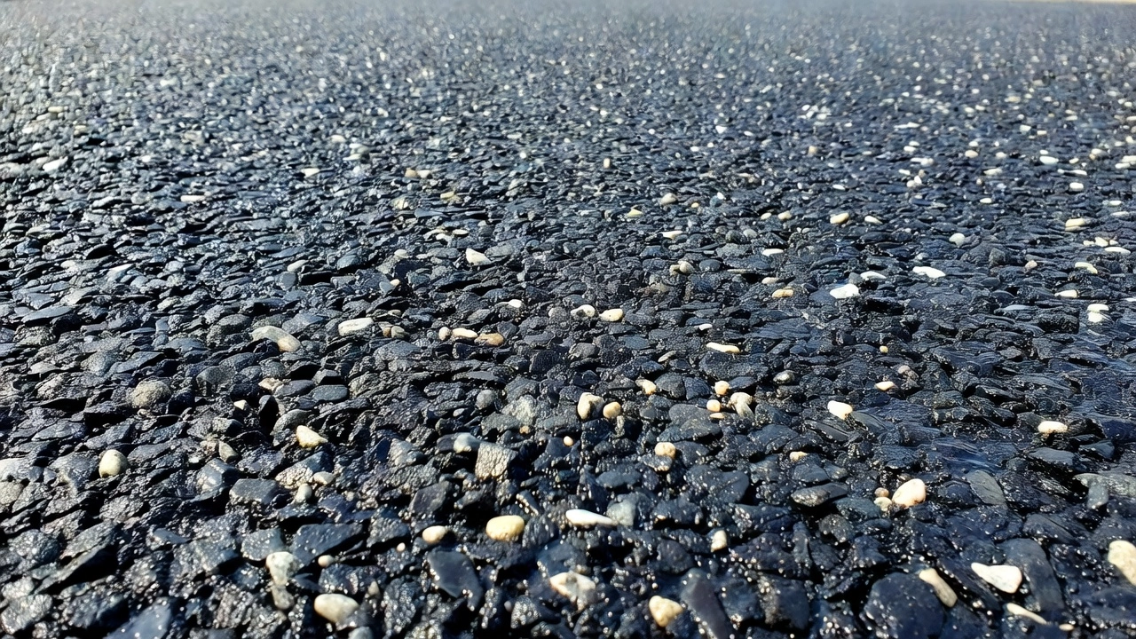
A chip seal (or chip and spray seal) is a pavement surface treatment consisting of a sprayed asphalt binder layer immediately covered with a single layer of aggregate chips, rolled to embed the chips. It provides a new skid-resistant wearing surface and waterproofs the pavement. Covers design, construction, chip retention, and post-construction FOD risk for airport applications.
1. Definition and Construction Sequence
A chip seal surface treatment — known globally as chip and spray seal, bituminous surface treatment (BST), or surface dressing — is a pavement preservation technique in which a thin film of asphalt binder is spray-applied to an existing pavement surface, immediately covered with a single layer of clean, pre-coated crushed aggregate chips, and then rolled to embed the chips into the binder film. The composite mat that results provides a new skid-resistant wearing surface, seals existing cracks up to approximately 6 mm (1/4 inch), and forms a waterproof membrane that protects the underlying pavement structure from moisture ingress and oxidative aging. The treatment is classified as a thin surface treatment because its total applied thickness — binder film plus aggregate chip height — ranges from only 6 to 15 mm, which is substantially thinner than the 25 to 50 mm typical of dense-graded hot-mix asphalt overlays. The AASHTO Construction Guide Specification Section 407 (Hot Applied Asphalt Chip Seal) and the FHWA Chip Seal Best Practices Guide both define this process with tightly controlled material and construction tolerances.
{{}}
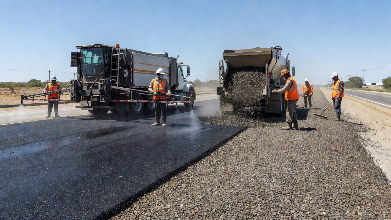
The construction sequence is precise and time-sensitive. The process begins with pavement surface preparation: cracks wider than 6 mm must be routed and sealed, potholes patched using cold-lay or hot-lay patching materials that must be fully cured (solvent-based patching materials may require several weeks), and any vegetation or debris removed. Tack coat may be required on aged or oxidized surfaces to ensure bond between the existing pavement and the new chip seal binder. The existing surface is swept clean with a rotary broom followed by vacuum sweeping to ensure binder-to-pavement adhesion is not compromised by residual dust. Per the AASHTO specification, cleaning must occur no more than 30 minutes prior to binder application to prevent recontamination of the surface, though this window may be extended with engineer approval. A distributor truck calibrated to deliver the specified binder application rate within plus or minus 5 percent of the design rate then sprays the binder at a temperature determined by the binder type — typically 140–180°C for hot-applied binders and 50–85°C for emulsions. The distributor must maintain uniform spray across the full bar width with no streaking, plugging, or misaligned nozzles. All nozzles must be oriented at the same angle, between 15 and 30 degrees, using the manufacturer-supplied wrench to ensure the triple-lap fan spray pattern that achieves full coverage. Distribution truck calibration is performed using a graduated dipstick and catch-pan test immediately before construction begins. The catch-pan test (ASTM D5624) involves placing a row of calibrated pans across the spray bar width, operating the distributor at the target speed and pressure, and measuring the volume of binder collected in each pan to verify uniformity within plus or minus 0.015 gal/yd² per distributor load. Immediately behind the distributor, an aggregate spreader (chip spreader) applies the aggregate at the specified spread rate, typically within seconds of binder application to ensure maximum embedment before the binder cools or breaks. The entire binder-to-chip window should not exceed 10–15 seconds for hot binders and 30–60 seconds for emulsions. The AASHTO specification requires a self-propelled, variable-width aggregate spreader mounted on pneumatic-tired wheels, with computerized spread control capable of maintaining the design spread rate within plus or minus 3 percent. Chip spreaders are typically self-propelled, hopper-fed units that deposit aggregate through a full-width metering gate. Pneumatic-tired rollers then compact the aggregate into the binder in two to three complete passes, with each pass overlapping the previous by at least one-half the roller width. The rolling speed is typically 8–15 km/h (5–9 mph), and rolling must be complete before the binder loses its workability. In emulsion applications, rolling must occur before the emulsion fully breaks (phase separates). Traffic is then allowed on the surface at controlled speeds typically under 40 km/h (25 mph) for an initial curing period of 24 to 72 hours, during which loose aggregate is progressively swept and collected. Speed restrictions are enforced through signage, radar speed feedback displays, and in some cases physical traffic control with flaggers or portable temporary traffic signals.
The chip seal does not contribute structural strength to the pavement. Road Note 39 (7th Edition) — the UK design guide published by the Transport Research Laboratory (TRL) — states explicitly that surface dressing does not strengthen the road structure, does not improve longitudinal or transverse profile, and does not improve riding quality. Its sole functions are to provide skid resistance, seal the surface against water ingress, retard surface deterioration, and extend the service life of a structurally sound pavement by 7 to 12 years. The treatment must therefore only be applied to pavements that have adequate structural capacity to carry the design traffic loads for the expected extended life period. The FAA Advisory Circular 150/5320-6G Chapter 4, Section 4.8 similarly addresses non-structural flexible overlays, confirming that chip seals do not increase the pavement structural capacity (PCN or PCR rating). The Federal Lands Highway Division (FLH) of the US Federal Highway Administration mandates that chip seal be applied only when the existing pavement condition index (PCI) is above 60 and the pavement is structurally sound, as confirmed by a falling weight deflectometer (FWD) survey where required.
2. Binder Types
The binder is the most critical component of a chip seal. It must possess sufficient adhesion to bond the aggregate chips to the existing pavement, sufficient cohesion to resist shear from traffic, and sufficient elasticity to accommodate thermal movements without cracking. Three broad categories of binder are used: asphalt emulsions, hot-applied binders, and polymer-modified binders. The AASHTO Guide Specification (Section 407) further subdivides hot applied binders into asphalt-rubber binder, rubber modified asphalt (RMA), and performance-graded (PG) binders.
Emulsion binders are the most widely used binder type for chip seals globally. An asphalt emulsion consists of microscopic droplets of asphalt cement dispersed in water through the action of an emulsifying agent and mechanical shear in a colloid mill. The continuous water phase keeps the asphalt fluid at ambient temperature, allowing cold application. Emulsions are classified by their setting rate: rapid-setting (RS), medium-setting (MS), and slow-setting (SS). For chip seals, rapid-setting emulsions — specifically cationic rapid-setting (CRS) grades — are almost exclusively specified because the chip seal process requires the emulsion to break (phase separate) quickly upon contact with the aggregate so that the asphalt droplets coalesce into a continuous binder film. Typical grades include CRS-1, CRS-2, and CRS-2P (polymer-modified). CRS-2 has a higher viscosity than CRS-1, providing a thicker binder film and better chip retention on coarse surfaces. The viscosity of CRS-2 measured by Saybolt Furol at 50°C ranges from 50 to 450 seconds per ASTM D244. Emulsion application temperatures range from 50°C to 85°C, depending on grade and ambient conditions. The emulsion breaks through water evaporation and chemical interaction with the aggregate surface. The time to break depends on temperature, humidity, aggregate moisture content, and emulsifier chemistry. In ideal conditions (25°C, low humidity), break occurs within 2 to 10 minutes. The water content of a typical chip seal emulsion is 30 to 40 percent by mass before break. After breaking and curing, the residual asphalt content is 60 to 70 percent. The AASHTO residue specification requires a minimum of 65 percent residue by distillation (AASHTO T59). Emulsions offer the advantages of low energy requirements (no heating of aggregate), reduced emissions, safer handling, and the ability to coat damp aggregate through active adhesion mechanisms facilitated by the emulsifier chemistry.
Hot-applied binders consist of penetration-grade asphalt cement heated to 140–180°C to achieve the viscosity required for spray application. Hot binders are typically specified as penetration grades 80/100, 120/150, or 150/200, with the softer grades used for colder climates or on more absorbent surfaces. The binder application temperature must be controlled within a narrow window: too hot and the binder drains into the existing pavement voids, leaving insufficient film thickness on the surface; too cool and the binder is too viscous to spread uniformly and cannot properly wet the aggregate surfaces. Hot-applied binder chip seals cure immediately upon cooling, offering the advantage that traffic can return sooner than with emulsion seals — typically within 1 to 4 hours. However, the need for heating equipment at the construction site, higher energy consumption, greater emissions, and the safety risks of handling material at 160°C+ make hot-applied binders less common than emulsions for routine chip seal programs. Hot-applied binders are generally reserved for high-traffic situations where rapid return to service is imperative. The AASHTO specification requires that performance-graded (PG) binders used for chip seals meet AASHTO M 320 or M 332 and exhibit an elastic recovery greater than or equal to 60 percent when tested in accordance with AASHTO T 301. This elastic recovery requirement ensures the binder can accommodate traffic-induced chip movement without permanent deformation.
Asphalt-rubber binder is a specialty hot binder that combines asphalt cement, extender oil (2.5 to 6.0 percent by weight of the asphalt binder), and crumb rubber modifier (CRM) at a minimum of 15 percent and up to 22 percent by mass of the total binder. The blending temperature must be between 350°F and 425°F (175°C to 218°C) when the CRM is added, and the blended materials must react for a minimum of 45 minutes at 350°F to 400°F. Asphalt-rubber binder meets the requirements of ASTM D6114. The thicker binder film from the rubber content provides exceptional chip retention and crack resistance. The AASHTO specification recommends that the aggregate for asphalt-rubber chip seals be a coarser gradation (Gradation A — 100 percent passing 3/4 inch, 70–100 percent passing 3/8 inch) compared to the finer gradation used with polymer-modified or PG binders, because the thicker binder film requires larger aggregate for proper embedment.
Rubber modified asphalt (RMA) is a terminal blend of PG asphalt binder with a minimum of 5 percent scrap tire rubber and 2 percent SBS polymer. Also called terminal blend, this product contains crumb rubber at 5 to 18 percent and meets the requirements of AASHTO M 320 with elastic recovery greater than 60 percent. RMA is widely used in Arizona, Texas, and California and provides a cost-effective alternative to asphalt-rubber binder with reduced field blending complexity.
Polymer-modified binders represent the highest performing category of chip seal binders. A polymer-modified binder is produced by blending asphalt cement with elastomeric or plastomeric polymers, most commonly styrene-butadiene-styrene (SBS) at typical dosages of 3 to 5 percent by mass of the binder. Other polymer types include styrene-butadiene rubber (SBR) latex, ethylene-vinyl acetate (EVA), and natural rubber latex. The polymer forms a three-dimensional network within the asphalt, substantially improving the binder properties. The performance benefits of polymer modification in chip seals are well documented. A Federal Lands Highway / FHWA study concluded that the added cost of polymer modification is justified by improved performance and recommended that all chip seals be performed with polymer-modified asphalt. Polymer-modified emulsions — designated CRS-2P or PME (polymer-modified emulsion) — offer faster break times and earlier chip retention compared to unmodified emulsions. The Colorado Department of Transportation specification for CRS-2P requires a minimum of 3.0 percent SBS or SB polymer by weight of asphalt cement and sets minimum toughness at 70 in-lb and tenacity at 45 in-lb per ASTM D5801. These toughness and tenacity values measure the binder’s resistance to deformation and are direct predictors of chip retention performance. The improved elasticity means the binder can accommodate thermal expansion and contraction cycles without cracking, delaying reflective cracking and reducing winter aggregate loss from snowplow damage. The enhanced cohesion provides greater resistance to traffic shear, allowing polymer-modified chip seals to be used on roads with average daily traffic (ADT) volumes exceeding 10,000 vehicles, where conventional chip seals would suffer rapid chip loss. The FAA requires a minimum of 3 percent polymer modification by weight of asphalt binder for P-623 spray seal coats. Polymer-modified hot binders are also available, typically produced by adding SBS to a penetration-grade binder at the asphalt terminal.
Binder Type
Application Temperature
Curing Time Before Traffic
Typical Service Life
Traffic Suitability
RS Emulsion (CRS-1, CRS-2)
50–85°C
24–72 hours
5–8 years
Low to medium ADT
Hot-applied (pen grade)
140–180°C
1–4 hours
6–9 years
Medium ADT
Polymer-modified emulsion (CRS-2P)
55–85°C
4–12 hours
8–12 years
Medium to high ADT
Asphalt-rubber (ASTM D6114)
175–218°C
1–4 hours
10–15 years
Medium to high ADT
Polymer-modified hot binder
150–190°C
1–2 hours
9–14 years
High ADT
Adhesion promoters are frequently added to the binder — at rates of 0.2 to 1.2 percent by mass of the binder — to improve the bond between the asphalt and aggregate, particularly when using siliceous (acidic) aggregates such as granite, quartzite, or sandstone that have inherently poor adhesion with unmodified asphalt. As documented by Nouryon, adhesion promoters function through two mechanisms: active adhesion, in which the surface-active agent reduces the contact angle of the bitumen on the aggregate surface, allowing the bitumen to displace water and coat the aggregate even when damp; and passive adhesion, in which the chemical bond between binder and aggregate resists displacement by water over the long term. The use of adhesion promoters is mandatory in several countries for all chip seal work to ensure durability and reduce the risk of early chip loss. The TRL Road Note 39 recommends a minimum of 0.5% adhesion agent (by mass of binder) for all surface dressing work in the UK and mandates 1.0% for siliceous aggregates.
3. Aggregate Selection and Application Rate
Aggregate selection for chip seals is governed by the principles of single-size gradation, shape, cleanliness, durability, and skid resistance. The aggregate chips must be single-sized — meaning that the nominal size and the nominal minimum size are close — to ensure that the chips pack in a single layer with minimal stacking and that the binder film between chips can provide consistent embedment. Typical aggregate sizes for single chip seals range from 4 mm to 14 mm nominal size, with 6 mm, 10 mm, and 14 mm being the most common. The UK Road Note 39 design procedure selects aggregate size based on a calculated equilibrium between traffic intensity and the hardness of the existing surface: harder surfaces and higher traffic volumes require smaller aggregate to limit long-term embedment that could lead to binder flushing. For airport pavements, Australian practice documented by Emery (2008) recommends that the top stone size be limited to a maximum nominal size of 7 mm to prevent tyre shredding and excessive tyre wear on wheel spin-up in the touchdown zone. The AASHTO specification divides aggregate gradations into two categories: Gradation A for asphalt-rubber binders (coarser: 100 percent passing 3/4 inch, 95–100 percent passing 1/2 inch, 70–100 percent passing 3/8 inch) and Gradation B for RMA and PG binders (finer: 100 percent passing 1/2 inch, 70–100 percent passing 3/8 inch).
{{}}
Aggregate shape is quantified by the flakiness index (the percentage of particles with thickness less than 0.6 times the mean sieve size) and the shape factor. The AASHTO specification limits flakiness index per FLH T 508 as follows: Class I (less than 500 ADT) — maximum 25 percent; Class II (501–5000 ADT) — maximum 20 percent; Class III (greater than 5000 ADT) — maximum 17 percent. Flaky particles orient flat-side-down during rolling and embed poorly, leading to premature chip loss. The ideal chip shape is cubical, with a length-to-thickness ratio below 3:1. Crushed-rock aggregates are mandatory — rounded gravel particles lack the angular interlock needed for chip retention, and they can dislodge under traffic shear. The minimum crushing requirement varies by traffic class per AASHTO T 335: Class III (highest traffic) requires a minimum of 95 percent one-face fracture and 90 percent two-face fracture. The Colorado specification increases this requirement to 100 percent crushed faces for all chip seal aggregate, regardless of traffic classification. ASTM D4791 governs the measurement of flat and elongated particles (maximum 12 percent at 3:1 ratio per many state specifications), while ASTM D5821 quantifies fractured faces.
Aggregate cleanliness is quantified by the Los Angeles Abrasion value and the Polished Stone Value (PSV) for skid resistance. The AASHTO specification defines abrasion limits by traffic class: Class I — maximum 37 percent loss; Class II — maximum 35 percent loss; Class III — maximum 30 percent loss per AASHTO T 96 (Los Angeles Abrasion). The PSV measures the resistance of aggregate to polishing under traffic, tested to standards such as BS EN 1097-8 or ASTM D3319. For high-stress applications such as curves, intersections, and airport runways, a minimum PSV of 55 to 65 is required, depending on traffic category and national specification. The UK Road Note 39 provides a comprehensive table linking site type, traffic volume, and minimum PSV — for example, motorways with traffic exceeding 3,250 commercial vehicles per lane per day require a minimum PSV of 68, while single carriageways with fewer than 100 commercial vehicles per day can use a PSV of 45. Soundness per ASTM C88 should be maximum 15 percent (sodium sulfate) or 25 percent (magnesium sulfate). The sand equivalent value per ASTM D2419 should be a minimum of 65.
Pre-coated aggregate is specified in the AASHTO Construction Guide for all hot-applied chip seals. The aggregate is uniformly coated with a Performance-Graded Asphalt (meeting AASHTO M 320 or M 322) at a central hot mix plant at a rate of 0.40 to 0.80 percent asphalt cement by weight of aggregate. The binder must have a minimum temperature of 250°F (121°C) at the time of pre-coating, and the end result must be a dust-free aggregate surface. Pre-coating improves initial adhesion between the chip and the freshly sprayed binder, reduces dust on the aggregate surface, and provides a uniform color contrast that aids quality control inspection of spread uniformity. The pre-coating also reduces the water absorption of porous aggregates, which can otherwise draw water from an emulsion binder and disrupt the breaking process.
Binder application rate is the mass of residual binder applied per unit area, expressed in kg/m² or gal/yd², and is determined by several factors: aggregate nominal size, aggregate absorption, surface condition (binder-rich versus binder-lean), traffic volume, and climate. The AASHTO specification provides the following standard application rate ranges: Asphalt-rubber binder — 0.6 ± 0.1 gal/yd² (approximately 2.7 ± 0.45 L/m²); RMA binder — 0.50 ± 0.10 gal/yd² (approximately 2.3 ± 0.45 L/m²); PG asphalt — 0.30 ± 0.10 gal/yd² (approximately 1.4 ± 0.45 L/m²). The specification emphasizes that the exact rate must be determined by the Engineer based on aggregate texture, absorption, and existing surface condition using approved design methods. Road Note 39 provides a systematic design method for calculating binder application rate based on the Average Least Dimension (ALD) of the aggregate, traffic level, and existing surface hardness. The general relationship is that binder application rate increases with aggregate size: a 6 mm aggregate seal requires approximately 1.0 to 1.3 kg/m² of residual binder; a 10 mm aggregate seal requires 1.3 to 1.6 kg/m²; and a 14 mm aggregate seal requires 1.6 to 2.0 kg/m². For emulsion binders, the application rate of emulsion is higher than the residual rate because of water content — typically by a factor of 1.4 to 1.7.
Aggregate spread rate is the mass of aggregate applied per unit area, expressed in kg/m² or lb/yd², and is designed to achieve a single layer of chips at a coverage of 80 to 90 percent of the surface when initially spread. The AASHTO specification provides standard aggregate application rate ranges: Asphalt-rubber — 30 to 40 lb/yd²; RMA — 25 to 35 lb/yd²; PG asphalt — 20 to 30 lb/yd². The Colorado specification provides more granular rates: 1/2 inch chip — 25 lb/yd² minimum; 3/8 inch chip — 23 lb/yd² minimum; 1/4 inch chip — 20 lb/yd² minimum. Over-application of aggregate results in stacked chips that will either dislodge or be crushed under traffic, creating FOD. Under-application leaves binder exposed to traffic pick-up and UV degradation. The theoretical aggregate spread rate is calculated as the product of the mean aggregate dimension, the aggregate dry-rodded unit weight (per ASTM C29), and a coverage factor. In practice, the spread rate must be field-adjusted based on a test strip constructed before the main production run.
4. Single vs Double vs Racked-In Seal
Chip seal systems are classified by the number of binder and aggregate layers applied. Each variant has specific applications, performance characteristics, and cost implications. The AASHTO Guide Specification notes that if the single-application chip seal process is repeated with another application of hot asphalt and another layer of cover aggregate, the process is known as a double chip seal.
Single seal is the most common system: one application of binder followed by one layer of aggregate. It is the simplest, uses the least material, and is suitable for the majority of pavement preservation applications where the existing surface is in good to fair condition and traffic stresses are moderate. The single seal provides adequate waterproofing and skid resistance for roads with average daily traffic (ADT) up to approximately 5,000 vehicles, and for general aviation airport pavements with moderate aircraft movements. The nominal texture depth achieved with a single seal ranges from 1.0 to 2.5 mm, depending on aggregate size, providing excellent macrotexture for high-speed skid resistance. Successful single seals on airport pavements are limited to general aviation aircraft below 5,700 kg according to Australian experience, with Emery (2008) concluding that single seals are not suitable for airline passenger jet aircraft. The AASHTO single seal aggregate application rates have the aggregate spreader calibrated at 20 to 40 lb/yd² depending on binder type and aggregate size.
Double seal consists of two alternating layers: a first application of binder with a larger aggregate, followed by a second application of binder and a finer aggregate. The double seal provides greater total binder film thickness — typically 3 to 5 mm versus 1.5 to 3 mm for a single seal — and delivers enhanced durability, better waterproofing, and longer service life. The larger aggregate in the first layer forms a structural matrix; the finer aggregate in the second layer fills voids and locks the matrix, preventing chip loss. The AASHTO specification permits double chip seal where specified in the contract documents. Double seals are specified for high-stress locations such as major intersections, roundabouts, heavy truck climbing lanes, and roads with ADT exceeding 10,000 vehicles. Double seals are also used for sealing gravel roads as a multi-stage pavement surface; in this application, the first seal may use 20 mm aggregate and the second seal 10 or 14 mm aggregate. Double seals produce a lower surface texture depth than single seals using the same top-size aggregate because the second finer aggregate fills the macrotexture voids. Typical texture depth for a double seal is 0.8 to 1.8 mm. The Australian survey of airport runways documented that double seals (10–14 mm stone on the lower layer and 5–7 mm stone on the upper layer, plus a prime) have proven very successful for new construction on airports serving Boeing 737-class aircraft.
{{}}
Racked-in seal (also called the racked-in system) is a variant in which one application of binder is covered with aggregate at approximately 90 percent of the single-seal spread rate, immediately followed by a second layer of smaller aggregate that is rolled into the first. The smaller chips lock the larger chips in position, creating a stable matrix without a second binder application. The racked-in system is used where traffic is particularly heavy and fast — such as high-speed rural arterials and motorways — and where the stresses on the surface are high. It occupies an intermediate position between single and double seals in both cost and performance. The racked-in system generally produces a higher texture depth than a double seal using the same size chippings because there is no second binder layer filling the inter-chip voids. TRL research has shown that racked-in seals perform well on roads where single seals have historically failed by chip loss at peak traffic periods.
Sandwich seal is a less common variant in which a layer of aggregate (chippings only, without binder) is applied before a single dressing — effectively a pre-coated surface layer. The sandwich system is used when the existing road surface is binder-rich, typically in wheel paths where bleeding or flushing has occurred. The dry aggregate layer absorbs excess binder from the existing surface, preventing the new dressing from flushing upward through the chip layer.
Seal Type
Binder Layers
Aggregate Layers
Typical Texture Depth
Typical Service Life
Relative Cost
Single seal
1
1
1.0–2.5 mm
5–9 years
1.0x
Racked-in seal
1
2 (different sizes)
1.2–2.2 mm
7–11 years
1.3x
Double seal
2
2
0.8–1.8 mm
9–14 years
1.7x
Sandwich seal
1
2 (one dry)
0.8–1.5 mm
6–10 years
1.5x
Cape seal is a composite treatment originally developed in Cape Town, South Africa: a chip seal is applied as the first layer, followed by a slurry seal or microsurfacing as the second layer, typically 4 to 6 weeks after the chip seal has cured. The chip seal provides the waterproof membrane and structural crack resistance, while the slurry seal provides a smooth, tight surface with reduced noise and improved aesthetics. The Cape seal is specified where the texture and noise of a conventional chip seal are unacceptable but where the waterproofing of a chip seal is still needed. Cape seals are used on airport pavements where low noise and low FOD risk are priorities but where a hot-mix asphalt overlay is not cost-justified. ASTM D7564 provides standard practice for construction of asphalt rubber Cape seal. The Cape seal approach has gained significant traction in southern Africa, Australia, and the southern United States for airport applications because it combines the structural waterproofing of a chip seal with the FOD-free surface of a slurry seal.
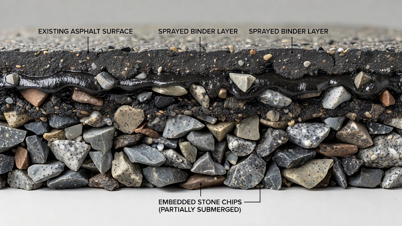
5. Chip Embedment and Rolling
The interface between chip and binder is the critical zone where chip seal success or failure is determined. Chip embedment refers to the depth to which each aggregate particle sits in the binder film and — in the longer term — in the existing pavement surface. The target for initial embedment immediately after rolling is that chips are embedded to 50 to 70 percent of their height into the binder film, leaving 30 to 50 percent exposed above the binder surface to provide the macrotexture necessary for skid resistance. If chips are embedded less than 50 percent, the bond area is insufficient and chips will dislodge under traffic shear. If chips are embedded more than 70 percent, the macrotexture is reduced (compromising skid resistance) and the binder may bleed upward around the chip in hot weather, causing flushing (also called fatting up or bleeding). After traffic compaction over the first 6 to 12 months, embedment typically increases by an additional 10 to 20 percent as the chips seat deeper under repeated loading. The relationship between binder application rate and chip embedment is governed by the Average Least Dimension (ALD) of the aggregate — the mean thickness of single-sized chips determined through the ALD test (BS 812 or the Texas ALD method). The Road Note 39 design procedure calculates binder application rate directly from ALD, traffic level, and surface hardness to achieve the target embedment range.
{{}}
Rolling is the mechanical operation that achieves initial chip embedment. Pneumatic-tired rollers are universally specified for chip seal rolling because their rubber tires conform to the chip surface, providing uniform contact pressure without crushing the aggregate. The AASHTO specification requires a minimum of three self-propelled pneumatic-tire rollers capable of ballast loading with water or sand to allow the machine weight to vary from 6 to 12 tons and achieve a minimum contact pressure of 80 psi (550 kPa). The tire pressure is typically set at 350 to 620 kPa (50 to 90 psi), depending on aggregate hardness and binder stiffness. The roller width must exceed 60 inches (1.5 m), and the alignment of the axles must be such that the rear-axle tires compact the voids untouched by the front-axle tires. The Colorado specification raises the pneumatic roller requirement to a loaded rate of 200–250 pounds per inch of rolling width with tire pressure not varying more than plus or minus 5 psi. Steel-wheel rollers have been used as the final roller on some chip seals with success, producing a more even final elevation with fewer prominent aggregate edges protruding above the surface (which reduces snowplow damage). However, the AASHTO specification warns that the disadvantage of steel-wheel rollers is the potential for crushing aggregate that cannot withstand the high stress imparted at the steel roll-chip interface. If steel rollers are used, they should be limited to 5 tons and vibration must not be engaged.
Two to three complete passes of the pneumatic roller are standard, with each pass overlapping the previous by at least half the roller width. Rolling speed is maintained at 8 to 15 km/h (5 to 9 mph) — slow enough to allow the chips to orient and embed under static load but fast enough to cover the binder surface before the binder cools (hot binder) or breaks (emulsion). For emulsion binders, rolling must be completed before the emulsion fully breaks. Once the emulsion has broken, the asphalt droplets have coalesced and further rolling cannot achieve additional embedment. The rolling window for emulsion chip seals is typically 10 to 30 minutes after binder application, depending on temperature and humidity. The minimum rolling production rate recommended by the Pavement Preservation and Recycling Alliance (PPRA) is 25,000 to 42,000 square feet per hour per roller (approximately 3,000 to 5,000 square yards per hour).
Secondary embedment occurs under traffic during the first 24 to 72 hours after construction. Traffic is deliberately directed over the new chip seal at controlled speeds — typically 25 to 40 km/h (15 to 25 mph) — to apply continued compaction without creating high shear stresses that would dislodge chips. Speed restrictions are enforced with signage, radar feedback, and, where necessary, physical traffic control (flaggers or portable signals). On high-speed roads, the speed restriction period may extend to 7 days or more where traffic volumes are high and chip retention is critical.
The relationship between aggregate size and embedment depth is fundamental. For a 10 mm nominal aggregate, the target embedment is 5 to 7 mm into the binder/surface. For a 6 mm aggregate, the target is 3 to 4 mm. The existing surface hardness determines how much of this embedment occurs in the binder film versus the existing pavement. On hard existing surfaces — concrete pavements, aged HMA surfaces — most embedment occurs within the binder film itself, requiring a thicker binder film. On soft surfaces — newly placed HMA, binder-rich surfaces — the chips embed more readily into the existing pavement, allowing a thinner binder film. This is the basis of the Road Note 39 design procedure, which categorizes road surface hardness into five classes (very hard to very soft) and adjusts binder application rate accordingly. The Texas Seal Coat Manual (2017) provides a modified design procedure (the Kearby method for PG binders and the Kirby method for RMA binders) that accounts for surface condition through an existing surface condition factor ranging from 0.9 (flush/binder-rich surface) to 1.2 (dry/aged/porous surface).
6. Loose Chip Period and FOD Risk
The loose chip period is the interval immediately following chip seal construction during which un-embedded aggregate particles are present on the pavement surface. This is an inherent characteristic of chip seals: a small percentage of chips — typically 2 to 8 percent of the total spread aggregate — will not achieve adequate embedment during rolling and remain loose on the surface. These loose chips must be removed through progressive sweeping before the surface can be opened to unrestricted traffic. In airport applications, the loose chip period represents a Foreign Object Debris (FOD) hazard that must be managed with exceptional rigor.
FOD from chip seals consists of loose aggregate particles ranging from 4 mm to 14 mm in diameter. At aircraft jet blast velocities — which can exceed 250 km/h (155 mph) at takeoff thrust — a loose 10 mm aggregate chip becomes a projectile capable of causing: jet engine ingestion damage (fan blade nicking, compressor blade failure); airframe dents and paint damage; windshield and canopy fracture; tire tread damage and punctures; and damage to control surfaces and landing gear components. The FAA Advisory Circular 150/5210-24A on FOD Management identifies pavement surface treatments as potential FOD sources and requires that airport operators implement inspection and removal procedures during and after chip seal construction. Boeing’s FOD prevention guidelines further emphasize that surface treatment aggregate is a known FOD source on airfields and that strict controls are necessary.
The first sweeping is performed by rotary broom immediately after rolling and removes the primary loose aggregate mass — typically 1 to 3 percent of spread material. The second sweeping is performed after 4 to 12 hours of traffic, removing additional chips that become loosened by traffic action. A third sweep occurs after 24 hours. For airport chip seals, emergency sweeping equipment must be available on standby throughout the loose chip period, and the surface must be certified FOD-free before any aircraft operations are permitted. The FAA requires that for chip seal projects on Air Operations Area (AOA) pavements, a FOD management plan be included in the project specifications.
Sweeping equipment must be gentle enough to remove loose chips without dislodging well-embedded ones. Rotary brooms with polypropylene bristles are standard; steel bristles must not be used as they dislodge embedded chips. The Colorado specification goes further, requiring that only vacuum-designed sweepers with negative air pressure be used on airport chip seal projects, with a minimum hopper capacity of 10 cubic yards and a negative air pressure rating at the intake of 46 inches of water column. Mechanical pickup brooms are specifically prohibited because they can dislodge embedded chips. The sweeping sequence must be documented, and the airport operator must verify FOD clearance before each aircraft movement during the curing period.
Extended curing periods reduce FOD risk. For airport chip seals, minimum curing before unrestricted aircraft operations is 72 hours for emulsion-based seals and 24 hours for hot-applied seals, with polymer-modified binders allowing the shorter end of these ranges. The curing period is extended under cool, humid, or wet conditions. No chip seal should be opened to jet aircraft operations until the binder has fully cured, the surface has been swept to FOD-free condition, and a FOD walk has been conducted. The FHWA Chip Seal Checklist emphasizes that the project specification must include the number and timing of sweeping passes, the maximum allowable loose chip percentage before opening to traffic (typically 1 percent maximum by mass per unit area), and the requirement for a FOD walk on airfield pavements.
For airport chip seals, post-construction FOD monitoring must continue for at least 30 days, with daily FOD walks during the first week and weekly thereafter until the chip seal has stabilized. Any re-emergence of loose chips — caused by thermal cycling or traffic shear dislodging initially well-embedded chips — is immediately addressed. The ASTM D7000 Sweep Test for emulsified asphalt surface treatment samples provides a laboratory method to predict chip loss propensity before construction, measuring the percentage of aggregate dislodged under standardized brushing conditions. Values below 5 percent chip loss in the sweep test indicate acceptable chip retention performance for most traffic levels.
7. Chip Seal in Airport Contexts
The application of chip seal on airport pavements is a specialized practice governed by FAA Advisory Circular 150/5320-6G, ICAO Annex 14, and individual airport certification requirements. Chip seal is considered a non-structural flexible overlay under FAA guidance — it does not increase the pavement structural capacity (PCN or PCR rating) but can restore functional performance including skid resistance, surface waterproofing, and crack sealing.
The FAA specifies chip seal through Item P-609 (Chip Seal Coat) in AC 150/5370-10H. P-609 is not recommended by the FAA for use on airfield pavements subjected to routine turbo-prop and jet aircraft traffic; it may be used on overruns and other areas not subject to routine turbo-prop and jet operations. Item P-623 (Emulsified Asphalt Spray Seal Coat) is approved for use on all pavements except runways serving aircraft 30,000 lbs (5,670 kg) or less, as well as shoulders, overruns, roads, and parking areas. With FAA concurrence, P-623 may be specified for airports serving aircraft less than 60,000 lbs (27,216 kg) except for runways and acute-angled exit taxiways. The FAA requires that P-623 be applied only to pavements in fair or better condition (PCI ≥ 60 per ASTM D5340) with an SCI (Structural Condition Index) deduct value of less than 10. The FAA P-623 specification mandates polymer modification of the emulsion binder and requires a preconstruction test strip to verify binder application rate, chip spread rate, and chip retention.
FAA AC 150/5320-12C (Measurement, Construction, and Maintenance of Skid-Resistant Airport Pavement Surfaces) specifically addresses chip seals as a friction treatment. Section 2-7 states that chip seals can provide temporary improvement of surface friction and notes that latex added to the chip seal extends its effective life. The AC also requires that friction levels be maintained above minimum thresholds defined for runway pavement surfaces: the design objective for Mu-Meter measurements at 65 km/h (40 mph) is a friction coefficient of 0.72 for runways with average annual departures exceeding 2,100.
The ICAO Annex 14 Aerodrome Design Manual requires that any surface treatment applied to an operational pavement must not create a FOD hazard or an unacceptable reduction in friction characteristics. ICAO requires an average macrotexture of at least 1.0 mm (Mean Texture Depth, MTD) over the full runway width and length for new surfaces. Chip seal typically produces macrotexture of 1.0 to 2.5 mm MTD, easily meeting this requirement. The ICAO friction testing requirements mandate that runway friction levels be maintained above minimum friction levels specified in Annex 14, Volume I, Appendix A. The design objective level (DOL) for Mu-Meter measurements at 65 km/h is 0.72, the maintenance planning level (MPL) is 0.52, and the minimum friction level (MFL) is 0.42. Chip seal surfaces generally produce friction levels well above these thresholds when properly designed with high-PSV aggregate.
Australian practice, documented by Emery (2008) in the paper “Seals for Heavy Duty Airport Pavements,” provides extensive field experience with chip seal on airports serving Boeing 737 and 767 aircraft. A survey of 38 Australian civilian and military airports in 2004 found that seals were the runway surfacing on 11 runways serving airline aircraft, including 2 runways serving Boeing 737s and 1 serving a Boeing 767. The Australian experience established the following design parameters for airport seals: maximum top stone size of 7 mm to prevent tyre damage; double seal construction (10–14 mm lower layer, 5–7 mm upper layer) for jet aircraft pavements; triple seal or Cape seal for high-stress areas such as runway ends and turning nodes; and polymer-modified binders for enhanced durability. The Australian Success/Failure model for airport seals identified poor chip retention (due to inadequate embedment or poor aggregate-binder compatibility), flushing in hot climates, and FOD generation as the three primary failure modes.
For airport chip seals, the following design parameters are typical: polymer-modified CRS-2P emulsion binder at residual application rate of 1.4 to 1.6 kg/m²; 6 mm or 10 mm single-size aggregate with PSV greater than 60 and flakiness index less than 20; aggregate pre-coating with bitumen at 1 to 2 percent by mass to improve initial adhesion; and application only during warm, dry weather with ambient temperature above 15°C (60°F) and rising. The aggregate spread rate on airport surfaces is typically adjusted to the lower end of the range — 90 percent coverage rather than 100 percent — to reduce the number of excess chips that could become FOD.
Post-construction FOD control on airport chip seals follows a prescribed protocol. After rolling and initial sweeping, the surface is inspected by FOD walk — personnel walking shoulder-to-shoulder across the full pavement width, scanning for all loose material. Any loose chip concentration exceeding 1 chip per square meter triggers re-sweeping. The surface is not released for aircraft operations until three consecutive FOD walks (each separated by a traffic period) pass with zero loose chips identified. Once released, the surface is subject to daily FOD walks for the first 14 days and weekly walks for the next 30 days.
8. Condition Assessment
Condition assessment of chip seal surfaces requires specialized inspection protocols distinct from those used for hot-mix asphalt pavements. The primary distress modes in chip seals are chip loss (fretting or raveling), binder flushing (fatting up or bleeding), reflective cracking, and aggregate polishing. The assessment must evaluate both the condition of the surface and the remaining service life. Unlike HMA pavements where structural assessment via falling weight deflectometer (FWD) is routine, chip seal condition assessment focuses almost entirely on functional surface characteristics because the treatment carries no structural capacity. The assessment process begins with a visual survey conducted at walking speed, recording distress types, severity, and extent according to standard methodologies such as ASTM D5340 for airport pavements and ASTM D6433 for roads.
Chip loss is quantified by counting missing aggregate particles per unit area. A chip loss of 0 to 5 percent of the surface area is considered normal wear. Loss of 5 to 15 percent indicates advancing deterioration that requires monitoring. Loss exceeding 15 percent signifies functional failure — the waterproofing membrane is compromised and skid resistance is reduced. Chip loss is most severe in wheel paths, at intersections, on curves, and on grades — locations where traffic shear stresses are highest. Microscopic examination of dislodged chips can reveal the failure mode: if the chip underside is clean and free of binder, the failure is adhesive (binder-chip bond failure); if binder residue remains on the chip, the failure is cohesive within the binder film itself. This distinction guides the selection of corrective measures — adhesive failure may require an adhesion promoter in the replacement treatment, while cohesive failure may require a harder or polymer-modified binder grade. The ASTM D7000 sweep test can also be used on field samples to quantify chip loss potential.
Binder flushing (also called bleeding or fatting up) occurs when excess binder rises to the surface above the chip tops, reducing macrotexture and skid resistance. Flushing is quantified by measuring the loss of texture depth using the sand patch test (ASTM E965) or volumetric patch technique (BS EN 13036-1). A surface texture depth below 0.4 mm indicates severe flushing and loss of skid resistance. Flushing is caused by: excessive binder application rate; aggregate embedment deeper than 70 percent under heavy traffic; softening of binder in hot weather; and application over an existing binder-rich surface without adjusting the design binder rate. Flushing typically appears first in wheel paths, where traffic-induced compaction drives the binder upward. In advanced flushing, the chip tops become completely submerged in binder, creating a smooth, binder-rich surface that is extremely slippery when wet — a condition that is a safety hazard requiring immediate corrective action. The International Airport Review notes that flushing on airport runways reduces friction below ICAO minimum friction levels and requires immediate grooving, friction restoration, or overlay.
Reflective cracking in chip seals occurs when cracks in the underlying pavement propagate through the chip seal layer. Because chip seal is a thin treatment (typically 6 to 15 mm total thickness), it has limited resistance to crack reflection. Cracks wider than 3 mm that reflect through the chip seal break the waterproofing membrane and allow moisture ingress. Crack sealing of the underlying pavement before chip seal application is essential. Reflection cracking is minimized when polymer-modified binders are used, as the polymer elasticity allows the binder film to stretch under crack movement. A fog seal applied over the chip seal can extend the crack resistance by an additional 1 to 3 years by providing an elastic covering layer.
Aggregate polishing is the wearing of chip surfaces under traffic, reducing microtexture and macrotexture. Polishing is assessed by measuring the skid resistance using a locked-wheel or fixed-slip friction tester. The rate of polishing depends on the aggregate PSV — higher PSV aggregates polish more slowly. A friction reduction of 20 to 30 percent over the service life is normal. When friction levels fall below the minimum threshold for the road or runway category, the chip seal has reached the end of its functional service life. The Mu-Meter and GripTester are the most commonly used continuous friction measurement devices for airport runways, providing friction data correlated to the ICAO categories.
The Pavement Condition Index (PCI) survey methodology for chip seals follows ASTM D5340 for airport pavements and ASTM D6433 for roads. The distress types recorded in a PCI survey of chip seal surfaces include: reveling/chip loss (counted in m² or as percentage of area); bleeding/flushing (m²); polished aggregate (m²); reflective cracking (linear meters); and weathering (m²). A chip seal with a PCI above 70 is in good condition; a PCI of 50 to 70 indicates fair condition requiring intervention within 1 to 3 years; a PCI below 50 indicates poor condition requiring replacement or overlay. The International Organization for Standardization (ISO) does not have a dedicated chip seal condition standard, so the ASTM methodology is the de facto international reference.
Distress Type
Measurement Method
Acceptable Level
Warning Level
Failure Level
Chip loss (raveling)
Visual count per m²
< 5% area
5–15% area
> 15% area
Binder flushing
Sand patch texture depth
> 1.0 mm
0.4–1.0 mm
< 0.4 mm
Reflective cracking
Crack width measurement
< 1 mm
1–3 mm
> 3 mm
Aggregate polishing
Friction number (FN)
> FN40
FN28–FN40
< FN28
Texture depth loss
Sand patch / volumetric
> 0.8 mm
0.4–0.8 mm
< 0.4 mm
Nondestructive testing for chip seal condition assessment includes laser profilometry for macrotexture measurement (Mean Profile Depth, MPD, per ASTM E1845), ground-penetrating radar (GPR) for detecting moisture trapped beneath the chip seal, and thermography for detecting binder application rate variations. Laser texture measurement can identify flushing and chip loss trends before they become visible, enabling predictive maintenance interventions. The CT Meter (Circular Texture Meter) provides non-contact texture measurement that correlates well with the sand patch method. For airport applications, the British Pendulum Number (BPN) per ASTM E303 is commonly used as a spot-check friction measurement at specific locations such as runway ends and taxiway turnoffs.
9. Performance and Limitations
The performance of a chip seal is a function of design quality, construction quality, material quality, traffic loading, and climate. When all factors are optimized, a chip seal provides 7 to 12 years of service life on pavements in good condition, as documented by the FP2 (formerly Asphalt Pavement Alliance) and FHWA performance studies. On pavements in fair condition, service life drops to 5 to 7 years. On pavements in poor condition — those with significant cracking, rutting, or deterioration — chip seal service life is 3 to 5 years or less, and the treatment is unlikely to be cost-effective. The timing of chip seal application within the pavement life cycle is critical: the ideal application window is when the pavement is still in good condition (PCI 70 to 100) with only early signs of surface deterioration such as oxidation, minor raveling, or loss of friction.
The cost of chip seal is substantially lower than hot-mix asphalt overlay. Typical unit costs in North America range from $1.50 to $4.00 per square yard (approximately $1.80 to $4.80 per square meter), depending on binder type, aggregate type, and geographic region. This compares with $5.00 to $12.00 per square yard for a 50 mm (2 inch) HMA overlay. The cost advantage is significant, but the chip seal does not provide structural improvement, does not correct profile irregularities, and does not improve ride quality — it only extends the functional life of a structurally sound pavement. The cost-effectiveness ratio — treatment cost divided by years of life extension — makes chip seal one of the most efficient pavement preservation treatments when applied at the right time. A chip seal at $2.50 per square yard providing 8 years of life extension yields a cost of $0.31 per square yard per year, compared to an HMA overlay at $8.00 per square yard providing 12 years at $0.67 per square yard per year. Life-cycle cost analysis (LCCA) using net present value methods consistently demonstrates that chip seal programs reduce the total cost of pavement ownership by 30 to 50 percent over a 30-year analysis period when applied as part of a systematic pavement preservation program.
Limitations of chip seal are substantial and must be recognized for appropriate treatment selection. Chip seal cannot be applied over pavements with structural failures, including alligator cracking, fatigue cracking, base failures, or subgrade weakness. The maximum allowable rut depth before chip seal is 9 mm (3/8 inch) — deeper ruts cannot be filled by the chip seal and will remain visible and may cause water ponding. The maximum allowable crack width before chip seal is 6 mm (1/4 inch) — wider cracks must be individually sealed before chip seal application. Chip seal should not be applied over pavements with entrapped moisture, as the seal will trap the moisture and accelerate stripping and moisture damage of the underlying pavement. Chip seal must not be applied in cold weather — minimum ambient temperature of 10°C (50°F) and rising for emulsion binders, 5°C (40°F) for hot binders. The FAA P-623 specification additionally requires that no rain be anticipated within 8 hours of application completion. The Colorado specification further restricts application to when both pavement and air temperatures are above 50°F (10°C) and rising and the pavement is not moist. Application in cool or damp conditions prolongs curing, reduces chip retention, and can cause complete treatment failure. Chip seal generates noise — the macrotextured surface produces tire-pavement noise 3 to 6 dB higher than HMA surfaces, which may be objectionable in residential areas.
Traffic accommodation is a significant operational consideration. The loose chip period requires speed restrictions (25 to 40 km/h) for 24 to 72 hours, traffic control personnel or devices, and progressive sweeping. For high-traffic roads and airports, traffic accommodation costs can approach or exceed the treatment cost. The total user delay cost must be factored into the life-cycle cost analysis. Polymer-modified binders reduce the curing period and, therefore, reduce traffic disruption. The AASHTO specification requires a preconstruction meeting to discuss, among other items, the traffic control plan and expectations for traffic accommodation during construction and curing.
Quality control during construction is a critical factor in chip seal performance. The AASHTO specification requires submission of a quality control plan and mix design for approval before construction. A test strip (also called a trial strip or calibration strip) of minimum 500 to 1,000 linear feet (150 to 300 meters) must be constructed before the main production run. The test strip serves to verify: binder application rate and distributor calibration; aggregate spread rate and spreader calibration; chip embedment depth; roller pattern and number of passes; chip retention under traffic; and overall appearance and uniformity. The test strip is evaluated by the Engineer, and no production work proceeds until the test strip is accepted. If production conditions change (different binder, different aggregate, different weather), a new test strip may be required. The binder distributor must be calibrated using a catch-pan test before each day’s production, and the results recorded.
10. Comparison with Slurry Seal and Microsurfacing
Chip seal, slurry seal, and microsurfacing are all thin pavement surface treatments, but they differ fundamentally in construction method, material composition, performance characteristics, and optimal application conditions. Understanding these differences is essential for selecting the correct treatment for a given pavement condition, traffic level, and performance requirement.
Slurry seal is a mixture of emulsified asphalt, well-graded fine aggregate (typically 0 to 4.75 mm), mineral filler, and water, mixed in a continuous-flow pugmill and applied to the pavement surface at a thickness of 3 to 6 mm. Slurry seal is applied by a specialized slurry seal machine that mixes the materials on board and spreads the slurry through a squeegee-type box as the machine moves forward. The mixture is fluid at application and cures by water evaporation, leaving a thin, smooth, dense surface. Slurry seal provides excellent sealing of fine cracks, surface restoration of oxidized or raveled pavements, and improved friction. However, slurry seal provides limited macrotexture (typical texture depth of 0.3 to 0.6 mm) and therefore has lower skid resistance at high speeds compared to chip seal. Slurry seal is suitable for low- to medium-traffic roads and general aviation airport pavements where high-speed friction is not critical. Slurry seal does not create a FOD risk because no loose aggregate is used. Slurry seal cost is typically $1.00 to $2.50 per square yard — somewhat lower than chip seal — but service life is shorter, typically 3 to 6 years. The ISSA A105 specification governs slurry seal materials and construction.
Microsurfacing is a polymer-modified version of slurry seal but with fundamental differences in material design. Microsurfacing uses polymer-modified emulsified asphalt (typically SBS or SBR latex at minimum 3% polymer solids based on bitumen weight per ISSA A143), well-graded fine aggregate (typically 0 to 9.5 mm), mineral filler, water, and controlled amounts of Portland cement or other additives to control break time. The distinguishing characteristic of microsurfacing is that the mixture is designed to break and cure chemically — not just by water evaporation — allowing rapid setting and early return to traffic, typically within 1 to 2 hours. Microsurfacing can be applied in thicknesses of 4 to 12 mm, can be used to correct minor rutting (up to 30 mm) by filling ruts with a specialized rut box, and provides a dense, smooth surface with moderate macrotexture (0.5 to 1.0 mm). Microsurfacing is suitable for medium- to high-traffic roads, including highways, intersections, and airport pavements where FOD risk must be minimized. The polymer modification provides excellent chip retention (the aggregate is fully bound within the mix, not surface-embedded), crack resistance, and durability. Microsurfacing cost ranges from $3.00 to $6.00 per square yard — higher than chip seal — but service life is 7 to 10 years on well-prepared pavements. The ISSA A143 specification requires that microsurfacing accept traffic within 1 hour after placement at 0.5 inch (12.7 mm) thickness.
The fundamental difference between chip seal and slurry seal or microsurfacing is the architecture of the surface. Chip seal creates a multi-layer composite: a continuous binder film on the pavement surface with aggregate chips embedded into it from above. The binder film is continuous and unbroken beneath the chips, providing an uninterrupted waterproof membrane. Slurry seal and microsurfacing create a single-layer monolithic mixture: aggregate particles are distributed throughout the binder matrix rather than embedded from above, and the waterproofing quality depends on the density and continuity of the binder in the mixture. For waterproofing of severely cracked surfaces, chip seal is generally more effective because the continuous pure-binder film bridges cracks without the aggregate interference present in slurry and microsurfacing mixtures.
Skid resistance comparison: Chip seal produces the highest macrotexture (1.0 to 2.5 mm mean texture depth) and therefore the best high-speed skid resistance. The Friction Number of a chip seal surface at 65 km/h (40 mph) ranges from FN40 to FN60, depending on aggregate PSV. Slurry seal produces macrotexture of 0.3 to 0.6 mm and friction numbers of FN30 to FN45. Microsurfacing produces macrotexture of 0.5 to 1.0 mm and friction numbers of FN35 to FN50. For airport runways where high-speed friction is critical (landing speeds of 250 to 300 km/h), chip seal provides the best friction performance — but the FOD risk is the limiting factor that often directs airport operators toward microsurfacing as the preferred treatment when a thin surface is required.
FOD comparison: Slurry seal and microsurfacing present negligible FOD risk because all aggregate is fully bound within the binder matrix — there are no loose surface particles. Chip seal presents FOD risk from the 2 to 8 percent of chips that remain unembedded after rolling. This is the single greatest operational disadvantage of chip seal in airport applications and the primary reason microsurfacing is increasingly preferred for airfield pavement preservation at commercial airports. The FAA’s P-623 specification allows chip seal on airport pavements serving aircraft up to 30,000 lbs, but the specification’s restrictions on runway use are directly attributable to FOD concerns.
Property
Chip Seal
Slurry Seal
Microsurfacing
Construction method
Spray binder + spread aggregate + roll
Mix and apply as slurry
Mix with polymer + apply with rut box
Application thickness
6–15 mm (chip height)
3–6 mm
4–12 mm
Macrotexture (MPD)
1.0–2.5 mm
0.3–0.6 mm
0.5–1.0 mm
Friction number (FN)
40–60
30–45
35–50
FOD risk
Moderate (loose chips)
Negligible
Negligible
Service life
5–12 years
3–6 years
7–10 years
Cost per square yard
$1.50–$4.00
$1.00–$2.50
$3.00–$6.00
Time to open to traffic
24–72 hours
2–8 hours
1–2 hours
Crack sealing ability
Excellent (continuous binder film)
Good (dense mixture)
Good (polymer-modified)
Rut correction
Cannot correct > 9 mm
Cannot correct
Can fill ruts up to 30 mm
Surface noise
3–6 dB higher than HMA
Same as HMA
Same as HMA
Airport suitability
GA pavements, FOD-managed
GA pavements
All airport pavements
The noise produced by chip seal is a significant consideration for airport applications. The macrotextured chip seal surface generates tire-pavement noise 3 to 6 dB higher than HMA surfaces at aircraft taxi speeds. At takeoff and landing speeds, the difference is less pronounced because aerodynamic noise dominates, but during taxiing and ground movements the additional noise from chip seal surfaces is measurable. This has implications for airport noise compliance, particularly for airports near residential areas. Slurry seal and microsurfacing produce noise levels comparable to HMA surfaces. The Cape seal — a chip seal with a slurry seal or microsurfacing overlay — is sometimes used to combine the waterproofing of a chip seal with the smoother, quieter surface of the slurry or microsurfacing layer, at a combined cost of $4.00 to $8.00 per square yard.
Treatment selection depends on pavement condition, traffic type and volume, performance requirements, noise constraints, FOD risk tolerance, and budget. Chip seal is the preferred treatment for: low- to medium-traffic roads where maximum waterproofing and skid resistance are needed; general aviation airport pavements that can accommodate a controlled loose chip period; pavement preservation where budget is the primary constraint; and surfaces where noise is not an issue. Slurry seal is preferred for: low-traffic roads and parking areas where surface smoothness and appearance matter; oxidation and raveling correction on aging pavements; and surfaces where FOD risk is unacceptable. Microsurfacing is preferred for: high-traffic roads and highways; commercial airport pavements where FOD risk must be minimized; rut correction up to 30 mm; and surfaces requiring rapid return to service. When the pavement requires both the waterproofing of a chip seal and the smooth surface of a microsurfacing without FOD risk, the Cape seal or an ultrathin bonded overlay (typically 15 to 25 mm of gap-graded HMA with a polymer-modified binder) should be considered.
The chip seal remains one of the most cost-effective pavement preservation treatments available, with over 80 years of proven performance on roads and airfields worldwide. Its limitations — FOD risk, noise, loose chip period — are well understood and can be managed through proper design, polymer modification, rigorous construction quality control, and appropriate application selection. For airport pavements, the trend is toward polymer-modified microsurfacing and Cape seals for operational pavements, with chip seal restricted to low-risk areas where its superior waterproofing and skid resistance provide the greatest benefit. The choice between chip seal and alternative thin surface treatments should always be based on a detailed engineering assessment of the specific pavement, traffic, and operational requirements — not on generalizations about which treatment is better.
Frequently Asked Questions
A chip seal (also called chip and spray seal, bituminous surface treatment BST, or surface dressing) is a pavement preservation treatment where a thin film of asphalt binder is spray-applied to an existing pavement surface, immediately covered with a single-sized crushed aggregate chips, and rolled to embed the chips into the binder. It provides a new skid-resistant wearing surface, seals cracks, and waterproofs the pavement structure.
A well-designed chip seal typically lasts 7-12 years on pavements in good condition, 5-7 years on pavements in fair condition, and 3-5 years on pavements in poor condition. The actual service life depends on traffic volume, climate conditions, aggregate quality, binder type, and construction quality.
Chip seal consists of a sprayed binder layer covered with embedded aggregate chips, creating a macrotextured surface with high skid resistance. Slurry seal is a mixed slurry of emulsified asphalt, fine aggregate, and mineral filler applied as a thin layer without embedded chips, resulting in a smoother surface. Chip seal is more effective for waterproofing and crack sealing, while slurry seal provides a tighter, smoother finish.
Chip seal is used on airport pavements primarily for low-traffic areas, general aviation runways, taxiways, aprons, and perimeter roads. Its use on high-speed commercial runways is limited due to FOD (Foreign Object Debris) risk from loose aggregate particles. When used at airports, polymer-modified binders, careful aggregate selection, and extended curing periods are essential to minimize chip loss.
Chip loss (also called fretting or raveling) is caused by: inadequate binder application rate, poor aggregate-binder adhesion, dusty or wet aggregate, traffic too soon after construction, insufficient rolling, cold weather application, incompatible aggregate and binder combinations, and high traffic shear stresses at intersections or turning areas.
A single chip seal has one application of binder and one layer of aggregate. A double chip seal has two alternating layers of binder and aggregate — the first layer uses larger aggregate and reduced coverage rate, followed by a second binder application and a finer aggregate. Double seals provide greater durability and are used on high-stress roads, gravel base surfaces, and where longer service life is required.
A polymer-modified chip seal uses asphalt binder that has been enhanced with polymers (such as SBS styrene-butadiene-styrene or latex) to improve elasticity, adhesion, cohesion, and temperature susceptibility. Polymer-modified chip seals offer faster cure times, better chip retention, greater resistance to reflective cracking, and longer service life compared to conventional unmodified chip seals.
The FAA specifies chip seal under Item P-609 (Chip Seal Coat) in AC 150/5370-10H. P-609 is not recommended for airfield pavements subjected to routine turbo-prop and jet aircraft traffic but may be used on overruns and areas not subject to routine jet operations. Item P-623 (Emulsified Asphalt Spray Seal Coat) is approved for pavements serving aircraft 30,000 lbs or less, excluding runways.
Chip seal should not be applied over pavements with structural failures, deep rutting (over 3/8 inch), severe potholes, extensive alligator cracking, or large unsealed cracks over 1/4 inch. It is also unsuitable for pavements with entrapped moisture, during cold or wet weather, or on surfaces that cannot accommodate the required curing period before opening to traffic.
Improve your pavement maintenance program
Contact TarmacView for expert guidance on chip seal inspection, FOD risk assessment, and pavement condition evaluation for airport and airfield pavements.
A seal coat is a thin asphalt-based surface treatment — typically emulsion or cutback — applied to existing pavement to waterproof, protect against oxidation an...
A slurry seal is a mixture of emulsified asphalt, fine aggregate, water, and additives applied as a thin (3-10 mm) overlay on pavement surfaces. It is a prevent...
Microsurfacing is a polymer-modified, cold-mix, quick-setting slurry surfacing system designed for high-traffic roads, airport runways, and taxiways. It provide...
25 min read
Pavement maintenance
Surface treatment
+3
Cookie Consent We use cookies to enhance your browsing experience and analyze our traffic. See our privacy policy.