Chloride Content Testing in Concrete
Chloride content testing determines the concentration of chloride ions at various depths in concrete, indicating corrosion risk to reinforcement. Total chloride...
30 min read
Concrete Testing
Corrosion
+3
Chloride attack is the penetration of chloride ions from deicing salts, marine environments, or contaminated materials into concrete, destroying the passive oxide film on reinforcing steel and initiating pitting corrosion. It is the primary cause of premature concrete bridge deck and parking structure deterioration. Covers chloride threshold, diffusion, testing, and prevention strategies.
Chloride attack is the ingress of chloride ions (Cl⁻) into concrete, leading to depassivation and corrosion of embedded reinforcing steel. It is widely recognized as the single most common cause of premature corrosion-induced deterioration of reinforced concrete structures worldwide. Per ACI 222R-01 (Protection of Metals in Concrete Against Corrosion), exposure of reinforced concrete to chloride ions is the major cause of premature corrosion of steel reinforcement. Unlike sulfate attack which degrades the concrete matrix itself, chloride attack targets the reinforcement while leaving the concrete matrix largely intact until expansive corrosion products cause cracking and spalling.
The process begins when chloride ions penetrate the concrete cover through various transport mechanisms and accumulate at the depth of the reinforcing steel. When the chloride concentration at the steel surface exceeds a critical threshold, the protective passive film that normally shields the steel breaks down locally, and active corrosion initiates. This makes chloride attack fundamentally different from other concrete deterioration mechanisms — it is an electrochemical process driven by the formation of corrosion cells on the reinforcing steel, not a chemical reaction within the cement paste.
Deicing salts are the most common source for highway and infrastructure structures in cold climates. Sodium chloride (NaCl), calcium chloride (CaCl₂), and magnesium chloride (MgCl₂) are applied to roads, bridges, and parking structures during winter months. These create concentrated chloride solutions on concrete surfaces, with typical runoff concentrations reaching 20,000–25,000 mg/L Cl⁻. The splash and spray zones on bridge decks, parapet edge beams, and parking slabs are most vulnerable, classified as XD3 conditions per Eurocode 2 (cyclic wet/dry exposure). In the United States alone, approximately 20–25 million metric tons of deicing salt are applied annually to roadways, making this the dominant chloride source for civil infrastructure.
Marine environments represent the second major source. Seawater contains approximately 19,000–20,000 mg/L (ppm) of chloride ions. Structures in coastal environments are classified per exposure class: XS1 for airborne salt exposure (coastal structures not in direct contact), XS2 for permanently submerged structures, and XS3 for tidal, splash, and spray zones. The XS3 classification is the most severe because wet/dry cycling concentrates chlorides at the concrete surface through evaporation. Wind-borne salt spray can carry chlorides up to 10 kilometers inland in coastal regions. Marine splash zones experience the highest chloride accumulation rates, often reaching surface concentrations of 1–2% chloride by weight of concrete within a few years of exposure.
Contaminated aggregates can introduce chlorides throughout the concrete mass from the time of placement, rather than through surface ingress. This occurs when unwashed marine-dredged aggregates or aggregates from saline sources are used in concrete production. Per ACI 318, maximum water-soluble chloride ion content limits are strictly prescribed: 0.06% by weight of cement for prestressed concrete, 0.15% for reinforced concrete exposed to chlorides in service, 0.30% for other reinforced concrete, and 1.00% for reinforced concrete dry or protected from moisture. Groundwater in arid regions or coastal aquifers can contain elevated chloride levels, affecting underground structures, foundations, and tunnels. Buried structures more than one meter below carriageway level are classified as XD2 (wet, rarely dry) per Eurocode 2.
Historically, calcium chloride was used as an accelerating admixture at dosages up to 2% by weight of cement. However, ACI 318 now prohibits calcium chloride or chloride-containing admixtures in prestressed concrete, concrete with embedded aluminum, or concrete exposed to severe sulfate conditions. Importantly, chloride-containing accelerators such as calcium nitrite and calcium nitrate can falsely elevate readings in the Rapid Chloride Permeability Test (ASTM C1202), creating a misleading impression of concrete quality.
The chloride threshold or critical chloride concentration (Ccrit) is the minimum chloride content at the steel depth required to initiate active corrosion. Per ACI 222R-01, when the chloride content exceeds this threshold, corrosion can occur provided that oxygen and moisture are present. The traditional threshold used in the United States is 0.4% total chloride by weight of cement, corresponding to approximately 0.6–0.9 kg/m³ of concrete. A more conservative value of 0.2% by weight of cement is used in some service life prediction models. European specifications sometimes use 0.05% water-soluble chloride by weight of concrete. Across the literature, the range typically cited is 0.03–0.07% water-soluble or 0.06–0.20% acid-soluble chloride by weight of cement.
For prestressing steel, the chloride threshold is significantly lower. ACI 222R-01 notes that while 0.4% Cl⁻ is typically used for conventional reinforcement, corrosion of prestressing steel can occur at lower threshold values, making prestressed structures particularly vulnerable to chloride-induced brittle failure.
The chloride threshold is not a single fixed value — it depends on multiple interrelated factors. Cement type plays a major role: higher tricalcium aluminate (C₃A) content binds more chlorides into Friedel’s salt, increasing the effective threshold. Type I/II cement with C₃A content of 8–14% provides better chloride binding than Type V with C₃A below 5%. The pH of the pore solution is equally critical. Normal concrete pore solution pH ranges from 13.0 to 13.5, maintaining a stable passive film on steel. Per the Hausmann criterion established in 1967, the critical [Cl⁻]/[OH⁻] ratio for depassivation is approximately 0.6. At pH 13.3, [OH⁻] ≈ 0.04 M, so the critical chloride concentration in pore solution is approximately 0.024 M or about 850 ppm. This corresponds roughly to the 0.4% Cl⁻ by weight of cement threshold in field concrete.
Carbonation lowers the pore solution pH and reduces the chloride threshold, creating a combined deterioration mechanism that can be more severe than either process alone. Temperature also affects the threshold — higher temperatures accelerate kinetics and reduce the threshold concentration. The steel surface condition matters as well, with pre-rusted steel showing different threshold behavior than clean steel. Finally, concrete quality influences the apparent threshold: a lower water-cement ratio produces a denser matrix, which increases the apparent threshold at the steel surface by limiting local moisture and oxygen availability.
At the steel-concrete interface, the passive film is stable within a specific electrochemical potential range. Chloride ions cause localized breakdown of the passive film when the corrosion potential (Ecorr) exceeds the pitting potential (Epit). The difference between Ecorr and Epit determines susceptibility to pitting initiation. Higher chloride concentrations shift Epit toward more negative (active) potentials, making depassivation more likely. Once pitting initiates, the local environment inside the pit acidifies, with pH dropping to 2–4, creating an autocatalytic corrosion cell that sustains itself independently of the bulk concrete conditions.
RILEM TC 235-CTC specifically addressed the complexity of chloride threshold concentrations in concrete, concluding that the threshold is not a single value but depends on concrete pore solution composition, steel-concrete interfacial condition, exposure conditions, and measurement method (total vs. free chloride). This understanding has important implications for service life modeling and specification writing.
The primary transport mechanism for chlorides in saturated concrete is diffusion, driven by concentration gradients. Fick’s Second Law of Diffusion is the governing equation:
∂C/∂t = D × ∂²C/∂x²
Where C is the chloride concentration at depth x and time t, and D is the chloride diffusion coefficient. The solution for semi-infinite media with constant surface concentration is:
C(x,t) = Cₛ − (Cₛ − Cᵢ) × erf[x / (2√(Dₐ × t))]
Where Cₛ is the surface chloride concentration, Cᵢ is the initial chloride content, Dₐ is the apparent chloride diffusion coefficient, and erf is the Gauss error function. This equation forms the basis for service life prediction models of concrete structures in chloride environments, including the widely used Life-365™ software.
The chloride diffusion coefficient varies by several orders of magnitude depending on concrete quality and composition:
| Concrete Type | Diffusion Coefficient D (×10⁻¹² m²/s) | Chloride Penetrability |
|---|---|---|
| High w/c (>0.60), conventional PCC | >10 | High |
| Moderate w/c (0.40–0.50), conventional PCC | 5–10 | Moderate |
| Low w/c (<0.40), conventional PCC | 2–5 | Low |
| Fly ash / slag concrete | 0.5–3 | Very Low |
| Silica fume concrete (5–10%) | 0.1–1 | Very Low |
| High-performance concrete (w/c <0.35 + SCMs) | 0.05–0.5 | Negligible |
The diffusion coefficient is not constant over time — it decreases with age due to continued hydration, which refines the pore structure. This is modeled using an aging factor (m): D(t) = D₂₈ × (t₂₈/t)^m. The value of m ranges from 0.2 to 0.6 depending on concrete composition. Silica fume and slag concretes typically exhibit higher aging factors, meaning their diffusion resistance improves more rapidly over time compared to plain Portland cement concrete.
Chlorides exist in concrete in two forms with very different implications for corrosion risk. Free chlorides are dissolved in the pore water and are available to initiate corrosion at the steel surface. Bound chlorides are chemically bound or physically adsorbed to the cement hydration products and are harmless unless released. Chemical binding occurs when chlorides react with C₃A to form Friedel’s salt (3CaO·Al₂O₃·CaCl₂·10H₂O) and with C₄AF to form similar chloroaluminates. Higher C₃A content increases binding capacity. Physical binding involves adsorption of Cl⁻ ions onto calcium-silicate-hydrate (C-S-H) gel surfaces, though this mechanism is weaker than chemical binding.
Chloride binding is described mathematically using binding isotherms. The Langmuir isotherm (Cb = α × Cf / (1 + β × Cf)) and the Freundlich isotherm (Cb = α × Cf^β) are both used to model the relationship between free and bound chlorides. Binding reduces the apparent diffusion coefficient by effectively removing free chlorides from the transport system. However, there is a significant release risk: if concrete carbonates, the pH drops and Friedel’s salt decomposes, releasing previously bound chlorides back into the pore solution. This can trigger corrosion even without new chloride ingress, making carbonation a dangerous companion to chloride contamination.
Concrete provides steel with excellent corrosion protection through two primary mechanisms. First, the high alkalinity of the pore solution (pH 13.0–13.5) creates an environment where steel naturally passivates. Second, a passive film — a tightly adhering iron oxide layer (γ-Fe₂O₃) approximately 3–5 nanometers thick — forms on the steel surface, reducing the corrosion rate to approximately 0.1 μm/yr. Without this passive film, steel in concrete would corrode at rates at least three orders of magnitude higher.
Chloride-induced depassivation occurs when chloride ions penetrate the passive film at localized weak points. These weak points include sites where the steel-concrete interface contains defects, voids, or inclusions. The critical [Cl⁻]/[OH⁻] ratio of approximately 0.6 represents the point at which the passive film becomes thermodynamically unstable. Once depassivation occurs, the protective film is destroyed locally, and active corrosion begins on the exposed steel surface.
Per ACI 222R-01, corrosion is an electrochemical process requiring both anodic and cathodic half-cell reactions operating simultaneously. At the anode (inside the corrosion pit), iron oxidizes: Fe → Fe²⁺ + 2e⁻. The ferrous ions then react with hydroxyl ions to form ferrous hydroxide: 2Fe²⁺ + 4OH⁻ → 2Fe(OH)₂, which further oxidizes to ferric oxyhydroxide: 2Fe(OH)₂ + ½O₂ → 2FeOOH + H₂O. At the cathode (on the surrounding passive steel surface), oxygen reduction occurs: 2H₂O + O₂ + 4e⁻ → 4(OH⁻).
A critical aspect of pitting corrosion is acidification within the pit. Hydrolysis of ferrous ions produces hydrogen ions: Fe²⁺ + 2H₂O → Fe(OH)₂ + 2H⁺, causing the local pH to drop to values as low as 2–4. This acidic environment accelerates the anodic dissolution rate and attracts more chloride ions to maintain charge neutrality, creating an autocatalytic corrosion cell that is self-sustaining.
Chloride-induced pitting corrosion is characterized by a macrocell configuration. The anodic area is small and highly localized (the pit), while the cathodic area is large, encompassing the surrounding passive steel surface. This large cathode-to-small-anode area ratio creates an intense corrosion cell with corrosion rates that can be 100–1000 times higher than general (uniform) corrosion. The anodic current density at the pit can reach 10–100 μA/cm² compared to the passive current density of less than 0.1 μA/cm². Using the conversion factor of 1 μA/cm² = 11.8 μm/yr steel penetration, active chloride-induced corrosion typically proceeds at 10–100 μm/yr, while passive steel corrodes at less than 0.1–0.2 μm/yr.
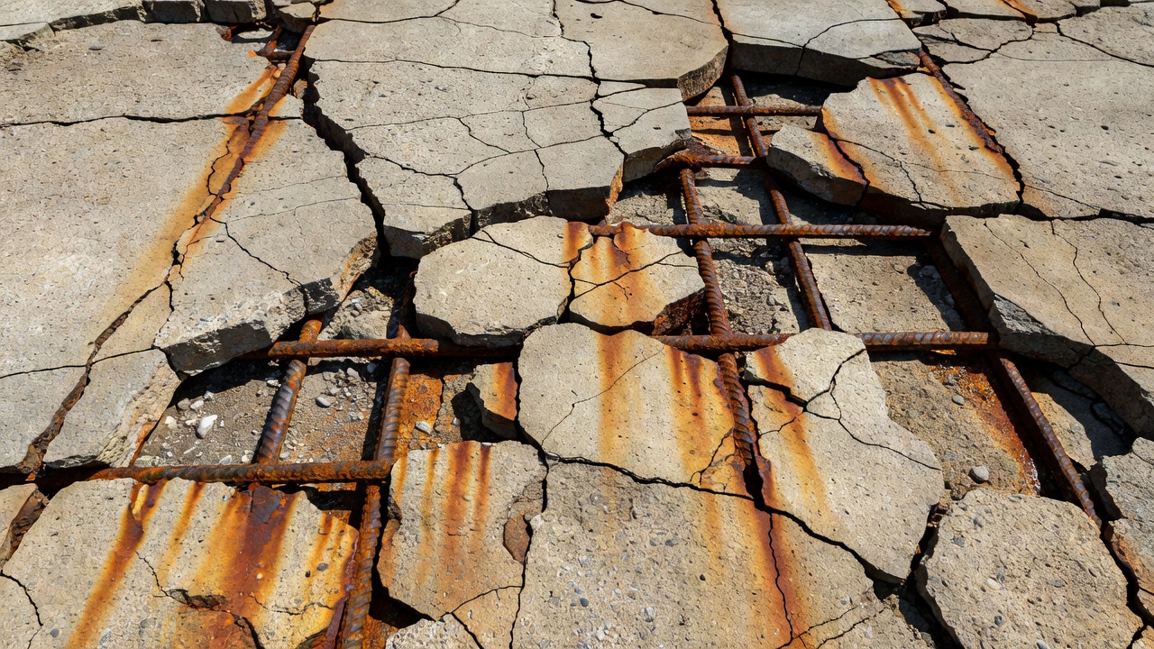
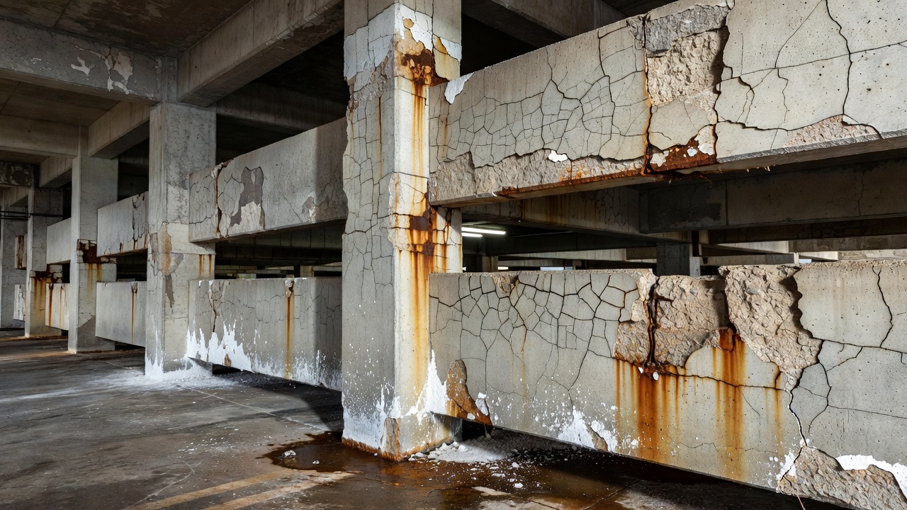
The consequences of chloride-induced pitting corrosion are severe and progressive. Volume expansion is the primary mechanical driver of damage — corrosion products (rust) occupy 2–10 times the volume of the original steel consumed. These expansive stresses generate tensile stresses in the surrounding concrete, typically causing visible cracking at 0.5–1.0% cross-sectional loss of the reinforcing bar. Cracking propagates along the rebar line, followed by spalling and delamination of the concrete cover. Section loss of reinforcement reduces structural capacity, while bond reduction between steel and concrete compromises composite action. For prestressed concrete, the risk is especially acute per ACI 222R-01 — even a small amount of metal loss from corrosion-induced pitting can induce brittle failure of the prestressing strand due to stress concentration at the pit.
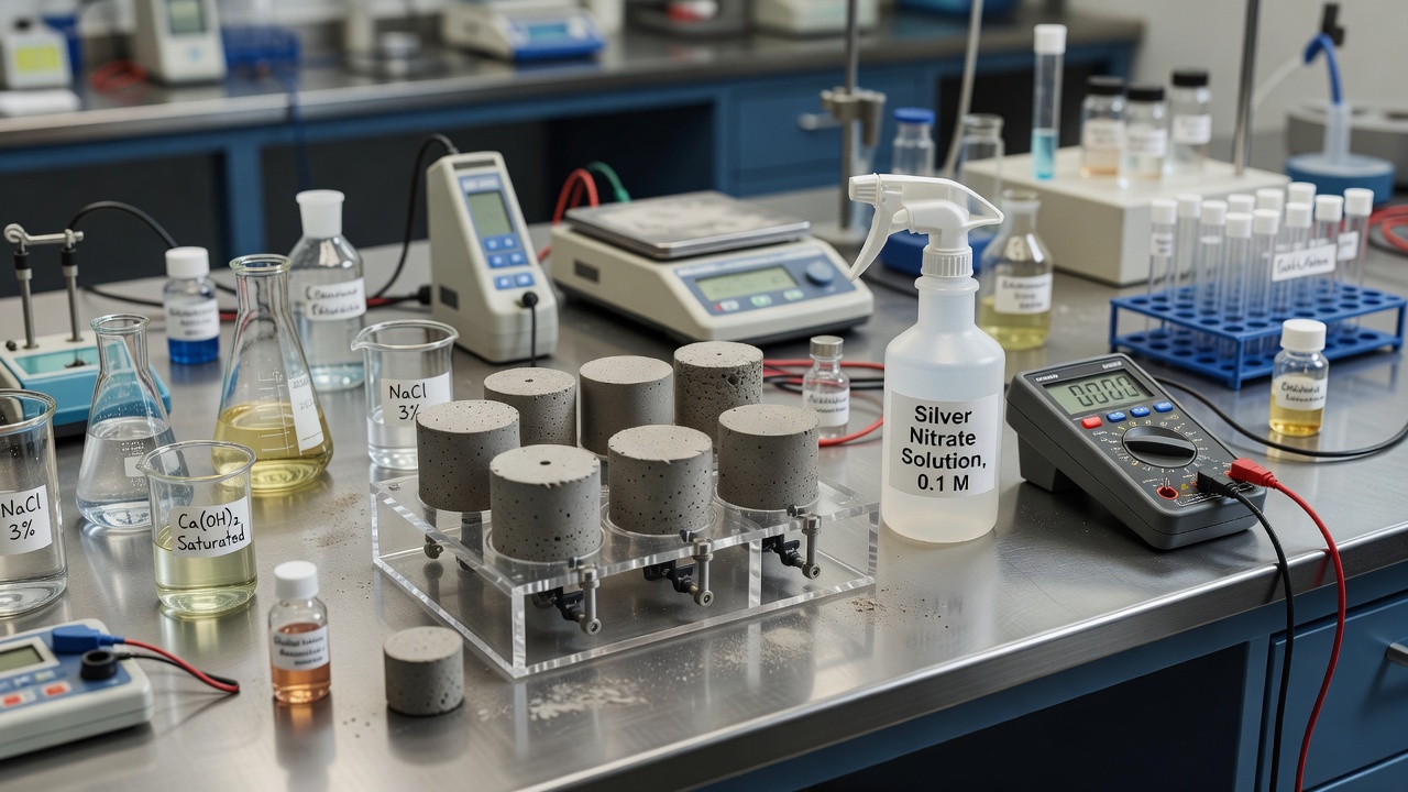
The RCPT is the most widely specified accelerated test for evaluating concrete resistance to chloride penetration in North America. The procedure involves obtaining a 100 mm diameter core or cylinder, cutting a 50 mm thick specimen, and coating the sides with epoxy. The specimen is vacuum-saturated (3 hours vacuum, 1 hour saturation, 18 hours soak) and placed in a test cell with 3% NaCl solution on the left (negative) side and 0.3N NaOH solution on the right (positive) side. A 60 V DC potential is applied for 6 hours, and the total charge passed is measured in coulombs.
Chloride Permeability Classification per ASTM C1202:
| Charge Passed (coulombs) | Chloride Permeability | Typical Concrete |
|---|---|---|
| >4,000 | High | High w/c ratio (>0.60) |
| 2,000–4,000 | Moderate | Moderate w/c (0.40–0.50) |
| 1,000–2,000 | Low | Low w/c (<0.40) |
| 100–1,000 | Very Low | Latex-modified or internally sealed |
| <100 | Negligible | Polymer-impregnated |
Critical limitations of the RCPT are well documented. The test does not measure chloride permeability directly — it measures concrete resistivity (ionic conductance under an applied voltage). The 60V DC potential is never present in field service conditions. Ionic admixtures such as calcium nitrite or calcium chloride can falsely elevate coulomb values. Precision is poor: same-operator variability can reach 42%, and inter-laboratory variability can reach 51% per ASTM C1202 precision statements. Sample age significantly affects results, and the method is not reliable for surface-treated (sealed) concretes.
This long-term test involves ponding 3% NaCl solution on concrete slab specimens for 90 days, followed by profile grinding at incremental depths (typically 1 mm increments). The acid-soluble or water-soluble chloride content at each depth is determined and plotted against depth to obtain a chloride profile. The profile is fitted to Fick’s Second Law to determine the apparent diffusion coefficient. Limitations include the very long test duration, sorption effects from dry sample preparation, and insufficient penetration depth for modern high-performance concretes.
The NT BUILD 492 non-steady-state migration test uses an external electric field to accelerate chloride ingress. A 50 mm thick, 100 mm diameter specimen is subjected to 10–30 V DC for 24–96 hours (depending on concrete quality), with 10% NaCl as catholyte and 0.3N NaOH as anolyte. After the test, the specimen is split axially and sprayed with 0.1M silver nitrate (AgNO₃), which forms a white silver chloride precipitate where chlorides have penetrated. The migration coefficient Dₙₛₛₘ is calculated from the penetration depth. Advantages over RCPT include measuring a true migration coefficient, not being affected by other ionic species, and applicability across a wide range of concrete qualities. The test is widely adopted in European specifications.
Half-cell potential mapping is the primary electrochemical technique for identifying corrosion activity in reinforced concrete structures. The method measures the electrochemical potential of steel reinforcement versus a reference electrode, typically copper-copper sulfate (CSE) or silver-silver chloride (Ag/AgCl). The reference electrode is placed on the concrete surface and connected to a voltmeter, with the other lead connected to exposed rebar. Measurements are taken on a grid of typically 1 m × 1 m spacing.
Corrosion Probability Interpretation per ASTM C876:
| Measured Potential (mV vs. CSE) | Probability of Corrosion Activity |
|---|---|
| >−200 mV | <10% (low risk) |
| −200 to −350 mV | Uncertain |
| <−350 mV | >90% (high risk) |
Factors influencing readings per RILEM TC-154 include concrete moisture content, cover depth, resistivity, and temperature. Humid, chloride-contaminated concrete typically shows potentials of −600 to −400 mV CSE. The method is qualitative — it provides corrosion probability, not corrosion rate. Small pits may be masked by the averaging effect of zonal measurements, and electrical continuity in the reinforcement must be verified.
LPR provides quantitative corrosion rate data by polarizing the steel ±10–20 mV from the corrosion potential (Ecorr) and measuring the current response. The polarization resistance Rp = ΔE/ΔI is used in the Stern-Geary equation: Icorr = B/Rp, where B ≈ 26 mV for actively corroding steel and 52 mV for passive steel.
Corrosion Rate Classification:
| Icorr (μA/cm²) | Corrosion Rate (μm/yr) | Expected Damage |
|---|---|---|
| <0.1 | <1.2 | Passive — negligible |
| 0.1–0.5 | 1.2–6 | Low — no cracking expected in 10–15 years |
| 0.5–1.0 | 6–12 | Moderate — cracking possible in 2–10 years |
| 1.0–10 | 12–120 | High — cracking likely in <2 years |
| >10 | >120 | Very high — active severe corrosion |
Modern devices such as the Giatec iCOR® use Ag/AgCl reference electrodes and can measure half-cell potential, corrosion rate, and concrete resistivity through the concrete cover without removing it, providing real-time assessment of corrosion activity.
Airport pavements face a unique combination of chloride exposure risks that distinguish them from highway or building structures. Coastal airports are subjected to marine salt spray (exposure classes XS1/XS3 per Eurocode 2), with runways, taxiways, and aprons directly exposed to airborne chlorides carried by wind. For airports located within 1–3 kilometers of coastlines, the chloride deposition rate can reach 500–1500 mg/m²/day on exposed surfaces. The combination of aircraft loads, jet blast, and salt spray creates particularly aggressive conditions for airfield concrete pavements.
Traditional chloride-based deicers (NaCl, CaCl₂, MgCl₂) are increasingly replaced at airports by non-chloride alternatives to reduce corrosion of aircraft components and aluminum structures. According to ACRP Synthesis 6 (Impact of Airport Pavement Deicing Products on Aircraft and Airfield Infrastructure), the most common modern aircraft deicers include potassium acetate (KAc), sodium acetate (NaAc), sodium formate (NaFm), and calcium magnesium acetate (CMA). While these non-chloride deicers significantly reduce corrosion risk for aircraft, research by the FAA (IPRF 05-7 and ACRP reports) has revealed that acetate and formate-based deicers can trigger or accelerate alkali-silica reaction (ASR) in airfield concrete pavements containing reactive aggregates. The deicers act as additional alkali sources, promoting the formation of expansive ASR gel. KAc deicers have been specifically linked to ASR-induced cracking at several US airports, creating a deterioration mechanism separate from but potentially concurrent with chloride-induced corrosion.
Cold-climate airport pavements simultaneously face freeze-thaw exposure combined with deicing chemical attack. Per ACI 318-19 Exposure Class F3 (freeze-thaw with deicing chemicals), the requirements are stringent: maximum water-cement ratio of 0.40, minimum compressive strength of 5,000 psi (35 MPa), mandatory air entrainment, and SCM limits per Table 26.4.2.2(b). The combined effect of freeze-thaw cycling and chemical attack can accelerate deterioration beyond what either mechanism would cause alone.
The ICAO Aerodrome Design Manual (Doc 9157, Part 3 — Pavements, 3rd edition, 2022) focuses primarily on structural design methods, including the ACR-PCR method for pavement classification, subgrade evaluation, and pavement thickness design. It does not provide detailed durability provisions for chloride exposure. This gap means that airport pavement designers must reference other standards (ACI 318, Eurocode 2, FAA Advisory Circulars) for chloride-related durability requirements.
Concrete cover — the distance from the concrete surface to the nearest reinforcing steel — is the primary physical barrier against chloride ingress. Per Fick’s Second Law, the time to corrosion initiation is proportional to the square of the cover depth: doubling the cover increases service life by approximately 4×. The relationship is expressed as: ti = x² / [4D × (erf⁻¹(Cs−Ccrit)/(Cs−Ci))]², where ti is the initiation time, x is cover depth, and the other parameters represent diffusion and concentration terms.
ACI 318-19 establishes Exposure Class C2 for concrete exposed to moisture and external chlorides in service — the most severe classification for corrosion risk. This class applies to parking structures, marine structures, and bridge decks. Requirements include maximum w/cm of 0.40 and minimum compressive strength of 5,000 psi (35 MPa). For concrete cover, ACI 318-19 Table 20.6.1.3.1 specifies:
| Exposure Condition | Cover (in.) | Cover (mm) |
|---|---|---|
| Cast against and permanently in contact with ground | 3 | 75 |
| Exposed to weather or in contact with ground (bars > #5) | 2 | 50 |
| Exposed to weather or in contact with ground (bars #5 or smaller, welded wire) | 1.5 | 40 |
| Slabs, walls, joists — not exposed to weather (#5 or smaller) | 0.75 | 20 |
| Beams, columns — not exposed to weather | 1.5 | 40 |
For corrosion protection under Category C2 exposure, ACI 318 permits a minimum cover of 2 inches (50 mm) for bars exposed to weather or ground contact, though greater cover is typically specified for severe marine or deicing exposures.
Eurocode 2 (EN 1992-1-1) provides more granular cover requirements based on exposure class, design working life (typically 50 or 100 years), and concrete quality. The nominal cover is calculated as cmin + Δcdev, where Δcdev is typically 10 mm.
Minimum cover for durability (cmin,dur) for chloride exposure classes:
| Exposure Class | Description | Min. Cover (mm) for 50-yr life | Concrete Class Min. |
|---|---|---|---|
| XD1 | Moderate humidity + airborne chlorides | 45 | C35/45 (w/c ≤0.45) |
| XD2 | Wet, rarely dry (e.g., submerged) | 50 | C35/45 (w/c ≤0.40) |
| XD3 | Cyclic wet/dry (bridge decks, car parks) | 55–60+ | C40/50–C45/55 (w/c ≤0.35–0.40) |
| XS1 | Airborne sea salt | 50 | C35/45–C40/50 (w/c ≤0.40–0.45) |
| XS2 | Permanently submerged | 45 | C35/45 (w/c ≤0.45) |
| XS3 | Tidal, splash, spray zones | 55–65+ | C45/55 (w/c ≤0.35–0.40) |
Per BS 8500-1 Table A4, for XD3 exposure with CEM I cement, cover of 55 mm requires concrete class C40/50, maximum w/c 0.40, and minimum cement content 380 kg/m³. For XS3 exposure, cover of 60 mm requires concrete class C45/55, maximum w/c 0.35, and minimum cement 380 kg/m³. These requirements reflect the recognition that cover depth and concrete quality are interdependent variables in corrosion protection.
SCMs are the most effective means of reducing chloride diffusion coefficients in concrete through pore refinement and enhanced chemical binding.
Fly Ash (ASTM C618) at 15–30% replacement reduces the chloride diffusion coefficient by 26–38%. The 30% replacement level achieves approximately 38% reduction, though levels above 40% may decrease resistance due to dilution of cementitious content. Benefits derive from the pozzolanic reaction, which consumes calcium hydroxide and produces additional C-S-H gel, refining the pore structure. Per ACI 318 for F3 exposure, maximum fly ash is limited to 25% of total cementitious material.
Slag/GGBFS (ASTM C989) at 50–70% replacement reduces D by 50–80% compared to plain Portland cement concrete. Slag refines pore structure and increases chloride binding capacity due to its higher effective C₃A content. Per ACI 318, maximum slag is 50% for F3 exposure. Ternary blends (fly ash + slag + Portland cement) provide synergistic benefits by combining the advantages of multiple SCM types.
Silica Fume (ASTM C1240) at 5–10% replacement is the most effective SCM for reducing chloride diffusion, achieving reductions of 80–95% compared to OPC concrete. The extremely fine particles (0.1–0.5 μm) fill capillary pores, dramatically reducing permeability. Per ACI 318 F3 exposure, maximum silica fume is limited to 10%, and when combined with other SCMs, the total SCM content is capped at 35% (fly ash + silica fume) or 50% (all SCMs combined).
Efficiency factors (k-values) quantify the relative effectiveness of different SCMs. Silica fume has a k-value of approximately 3–4 (1 kg of silica fume equals 3–4 kg of cement in terms of diffusion resistance), while Class F fly ash ranges from 0.4 to 0.7, and slag from 0.6 to 1.0.
Silanes and siloxanes are hydrophobic pore liners that create water-repellent surfaces without blocking vapor transmission. Typical service life ranges from 5–10 years depending on exposure severity and application quality. Epoxy and methacrylate coatings form continuous barrier films that physically block chloride-laden water ingress. Hydrogel treatments penetrate the concrete and react with calcium hydroxide to form additional C-S-H gel within the pores, immobilizing moisture and reducing permeability. A critical limitation per ASTM C1202 is that sealers may show low RCPT resistance even when ponding tests confirm effectiveness — alternative performance testing is needed for surface-treated concretes.
Fusion-bonded epoxy coating provides a physical barrier between steel and chlorides. Epoxy-coated rebar can withstand chloride concentrations 4–5 times higher than black steel before corrosion initiates. The coating thickness is specified as 175–300 μm (7–12 mils) per ASTM A775. Key considerations include careful handling to avoid holidays or pinholes (which can concentrate corrosion), incompatibility with cathodic protection due to shielding issues, and heavy dependence on quality control during fabrication, handling, and placement.
Impressed Current Cathodic Protection (ICCP) uses an external power source to supply protective current through inert anodes. Typical design criteria for steel in concrete range from 0.2–20 mA/m² of steel surface, with 0.2–2 mA/m² for corrosion prevention and 10–20 mA/m² for corrosion control in chloride-contaminated structures. Anode types include conductive coatings (e.g., CAS ICCP systems capable of up to 35 mA/m²), titanium mesh, conductive mortar, and discrete anodes. Modern ICCP systems achieve service lives of 15 years or more. Protection verification uses the 100 mV polarization decay or 100 mV depolarization criteria.
Sacrificial Anode CP (SACP) uses galvanic anodes (zinc, aluminum, magnesium alloys) without external power. Lower driving voltage limits application to structures with moderate concrete resistivity. Effective for localized protection in patch repairs and marine structures, with service life of 5–15 years depending on anode mass and current demand.
Calcium nitrite (Ca(NO₂)₂) is the most common corrosion inhibitor admixture. The nitrite ion (NO₂⁻) competes with chloride ions at the steel surface, passivating anodic sites and maintaining the passive film by oxidizing Fe²⁺ to Fe³⁺. Typical dosages range from 10–30 L/m³. Per ACI 222R, inhibitors can extend corrosion-free life, but effectiveness depends on concrete quality and exposure severity. Aminoalcohol-based organic inhibitors and sodium monofluorophosphate provide alternative chemistries, though all inhibitors are less effective in cracked concrete than in uncracked sections.
Waterproof membranes applied to bridge decks, parking garage slabs, and vertical walls prevent chloride-laden water from reaching the concrete surface. Sheet membranes (polymer-modified bitumen, PVC, polyolefin) and liquid-applied membranes (polyurethane, epoxy, acrylic) are available, but all require periodic maintenance and replacement. Stainless steel reinforcement per ASTM A955 (grades 316LN or Duplex 2205) provides excellent chloride resistance for critical structures where access for repair is limited, though at a cost premium of 4–8 times that of black steel.
The first indication of chloride-induced corrosion is typically rust-colored staining on the concrete surface, appearing along lines of reinforcement before visible cracking develops. As corrosion progresses, longitudinal cracks develop along rebar lines — this crack pattern is characteristic of chloride-induced corrosion and distinct from the random map cracking associated with ASR or freeze-thaw damage. Spalling and delamination of the concrete cover at rebar level represent advanced deterioration where the expansive corrosion products have generated sufficient tensile stress to fracture the cover concrete.
Hammer sounding or chain drag surveys identify delaminated areas by the hollow sound produced when tapping over debonded concrete. These techniques can be applied to large areas such as bridge decks, parking decks, and airfield pavements. Delaminated areas are delineated and mapped on the structure for repair planning. Ground Penetrating Radar (GPR) can identify delaminations at depth, while infrared thermography exploits temperature differentials during diurnal cycling to reveal delaminated areas.
Sample collection involves drilling powder samples at incremental depths (typically 0–10 mm, 10–20 mm, 20–30 mm, and continuing to at least the depth of reinforcement). Acid-soluble (total) chloride per ASTM C1152 dissolves the entire sample and measures all chlorides, both free and bound. Water-soluble (free) chloride per ASTM C1218 measures only chlorides in the pore solution and is a better indicator of corrosion risk. Potentiometric titration using silver nitrate (AgNO₃) with a chloride-specific ion electrode is the most common quantitative method. Colorimetric methods using silver nitrate spray on freshly split concrete surfaces reveal the chloride penetration front as a white silver chloride precipitate.
Results are typically reported as percent chloride by weight of cement (most common for threshold comparison), percent chloride by weight of concrete, or kg/m³ of concrete. The approximate conversion is 1% by weight of cement ≈ 0.15% by weight of concrete ≈ 2.5 kg/m³.
Microscopic analysis of concrete can identify the depth of chloride penetration (using AgNO₃ staining on thin sections), the presence of Friedel’s salt (confirming chloride binding has occurred), ASR gel (relevant when acetate/formate deicers are involved), microcracking from corrosion expansion, and the quality of cover concrete including w/c ratio estimation.
Using field data from the above tests, Life-365™ is the industry-standard model for chloride-induced corrosion service life prediction. The model uses Fick’s Second Law with a time-dependent diffusion coefficient and requires inputs including the 28-day diffusion coefficient D₂₈, aging factor m, surface chloride concentration Cs, critical threshold Ccrit, cover depth, and temperature. The model predicts time to corrosion initiation and time to cracking. The default threshold input is 0.05% total chloride by weight of concrete (equivalent to approximately 0.4% by weight of cement). This modeling approach enables engineers to evaluate alternative concrete mixtures, cover depths, and protection strategies on a life-cycle cost basis, optimizing both initial construction costs and long-term maintenance expenses.
The four-point Wenner probe (ASTM WK37880 / AASHTO TP 119) measures the electrical resistivity of the concrete cover as an indicator of moisture content and pore connectivity. Resistivity values correlate with corrosion risk: above 200 kΩ·cm indicates negligible risk, 100–200 kΩ·cm low risk, 50–100 kΩ·cm moderate risk, 10–50 kΩ·cm high risk, and below 10 kΩ·cm very high risk. Low resistivity indicates a saturated, connected pore structure that facilitates ionic transport and sustains corrosion currents, making it a valuable complementary measurement to half-cell potential mapping and chloride profiling.
Extend the service life of bridges, parking structures, and airfield pavements with advanced corrosion prevention strategies, quality concrete mixes, and professional inspection services. Learn how to identify, assess, and mitigate chloride-induced deterioration.
Chloride content testing determines the concentration of chloride ions at various depths in concrete, indicating corrosion risk to reinforcement. Total chloride...
Corrosion of reinforcing steel is the electrochemical deterioration of rebar within concrete, driven by chloride ingress or carbonation destroying the protectiv...
Sulfate attack is the chemical and physical deterioration of concrete caused by sulfate ions from soil, groundwater, seawater, or internal sources reacting with...