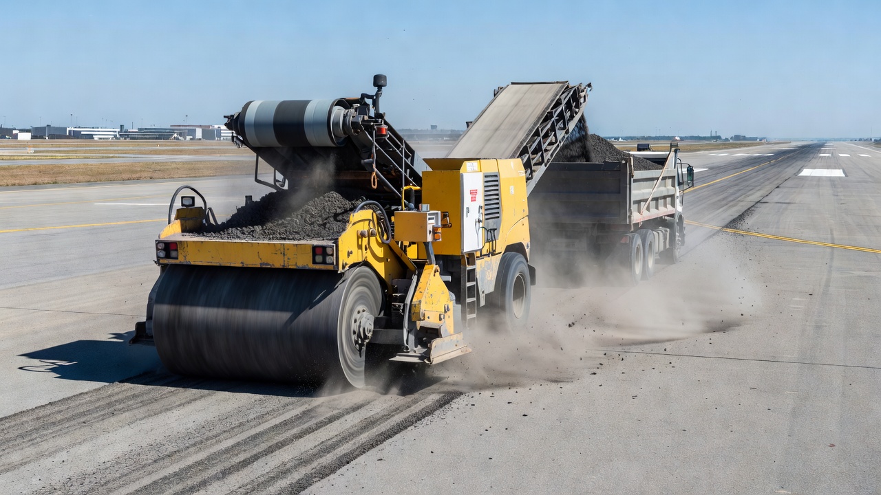
Cold planing, also called asphalt milling, is the mechanical removal of pavement layers to a specified depth and profile using a rotating drum with carbide-tipped teeth. It restores grade and cross-slope, removes distressed material, and produces RAP for recycling.
Cold Planing (Milling) of Asphalt Pavements
Definition and Equipment
Cold Planing (CP), also referred to as asphalt milling, pavement milling, or cold milling, is the controlled mechanical removal of the surface of an existing pavement to a specified depth, grade, and cross-slope using a self-propelled cold planing machine. The Asphalt Recycling and Reclaiming Association (ARRA) formally defines cold planing as “the controlled removal of the surface of the existing pavement to the desired depth, with specially designed equipment to restore the pavement surface to a specified grade and cross-slope.” The process originated in the late 1970s and has since become the preferred method worldwide for removing and reclaiming asphalt pavement materials.
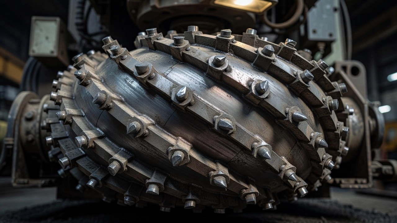
Primary Equipment Components. The cold planing machine is a self-propelled unit with sufficient horsepower, traction, and stability to maintain an accurate depth of cut. The central component is the cutting drum — a rotating cylinder wrapped with 2, 3, or 4 scrolls (spiral configurations) that move milled material toward the center for conveyor loading. Standard cutting drums are equipped with tool holders and replaceable carbide-tipped cutting tools (teeth) that contact and fracture the pavement surface. On a triple-wrap drum with 3 scrolls, cutting tools are typically spaced 15 mm (5/8 inch) apart horizontally. The drum generally operates in an “up-cut” direction, meaning the drum rotation moves upward relative to the machine’s forward travel direction, which controls the size of milled particles and surface texture.
Cutting Tools and Tool Holders. The cutting tools are carbide-tipped steel shanks that wear during operation and must be replaced regularly to maintain consistent cutting quality. No single style of cutting tool works universally — aggregate hardness, size, and abrasiveness are major factors determining tool selection and life expectancy. A cutting tool may last from one hour (on abrasive concrete or contaminated material) to several days (on standard asphalt). Tool holders are of two primary types: quick-change holder systems and weld-on holder and block systems. Holders wear over time and must be replaced to maintain a good quality cutting pattern. Holders may shear off if the drum strikes buried obstacles such as manhole frames or water valve boxes.
Standard Drum Widths. Cold planing machines are available with cutting drum widths ranging from 100 mm (4 inches) for trenching applications up to 4.2 m (14 feet) for full-lane milling. The standard width classifications are:
Drum Category
Typical Widths
Trenching
100, 200, 300 mm (4, 8, 12 inches)
Mini Planers
300, 400, 500, 600 mm (12, 16, 20, 24 inches)
Small Mills
1.0, 1.2 m (3, 4 feet)
Half-Lane
1.8, 2.1 m (6, 7 feet)
Full Lane
3.0, 3.4, 3.8, 4.2 m (10, 11.25, 12.5, 14 feet)
Material Handling Systems. The cutter housing contains all milled material during cutting. A carbide scraper blade drags on the textured milled surface behind the drum, removing all loose material except fine dust. A self-loading conveyor system, either front-loading or side-loading, transfers the milled material from the roadway into haul trucks operating in tandem with the cold planer. Modern machines use front-loading conveyors that improve visibility and maneuverability.
Water Spray Systems. Cutting asphalt generates a tremendous amount of heat due to friction between the cutting tools and pavement. Up to 2,000 gallons (7,570 liters) of water per hour must be constantly sprayed on the cutting tools and drum inside the cutter housing for cooling. The water spray system also serves to suppress airborne dust particles, controlling fugitive emissions and improving visibility for the operator and surrounding traffic. A water truck with a typical capacity of 2,500 gallons (9,460 liters) accompanies the cold planer on most projects.
Track Systems. Cold planers are equipped with either three or four tracks, each driven by separate hydraulic motors with traction-locking devices. Track systems have polyurethane or rubber track pads that provide uniform traction while minimizing damage to the underlying pavement surface. Modern track designs incorporate traction-locking that diverts power away from slipping tracks to those with grip, maintaining consistent forward motion and cutting quality.
Milling Depths
Cold planing can be performed at three distinct depth ranges depending on the project objectives, existing pavement condition, and the structural requirements of the rehabilitation strategy.
Surface Milling (6–50 mm / 0.25–2 inches). Surface milling removes only the top layer of the asphalt pavement to correct minor surface distresses such as raveling, bleeding, and polished aggregate. This depth is typically used when the underlying pavement structure remains sound and the objective is to restore skid resistance or prepare the surface for a thin overlay or surface treatment. Surface milling also serves to remove deteriorated surface treatments such as slurry seals, chip seals, or microsurfacing that have reached the end of their service life. The milled depth must be sufficient to remove all oxidized and aged binder from the surface layer.
Partial-Depth Milling (50–150 mm / 2–6 inches). Partial-depth milling removes one or more asphalt lifts while leaving the lower pavement layers intact. This is the most common application for cold planing prior to overlay placement. Typical milling depths for highway and airfield rehabilitation range from 50 to 100 mm (2 to 4 inches). Partial-depth milling removes wheel ruts, corrugations, shoving, and structural cracks that extend through the upper lifts. The depth is selected to expose sound material below the distressed zone, providing a clean, uniform substrate for the new overlay.
Full-Depth Milling (150–300 mm / 6–12 inches). Full-depth milling removes the entire asphalt pavement structure down to the base course or subgrade. This application is used when the existing asphalt has extensive structural distress, stripping, or age-hardening throughout its full thickness. Full-depth milling is also specified when grade or cross-slope corrections require removal of the entire pavement section, when the existing pavement profile has accumulated multiple overlay layers that have raised the surface above curb reveals or drainage structures, or when the existing pavement is to be replaced entirely using recycled materials. Typical maximum milling depths range from 300 mm (12 inches) for standard machines to 350 mm (14 inches) on specialized equipment.
The specified milling depth in project plans and specifications must account for the minimum depth required to produce a clean, uniform surface below the level of existing distress. The ARRA Recommended Construction Guidelines (CP101) note that typical milling depths fall between 25 mm and 300 mm (1 to 12 inches).
Surface Texture After Milling
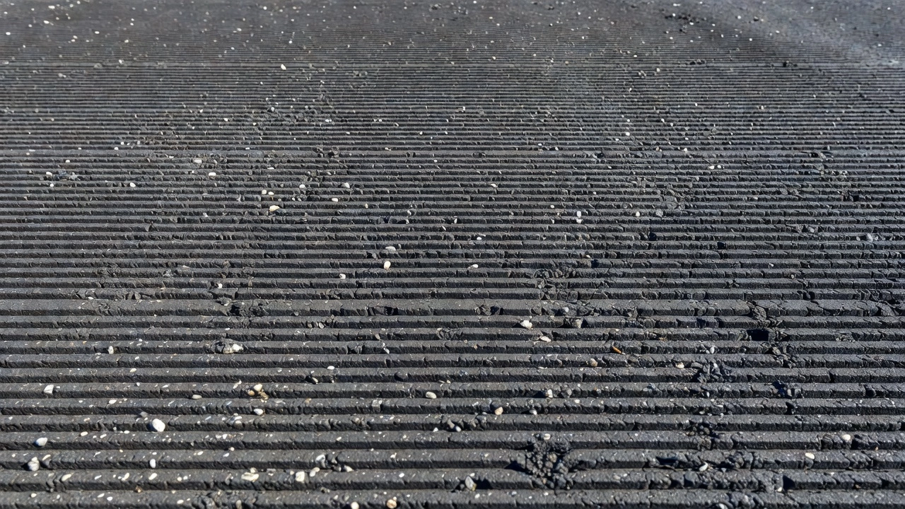
The surface texture produced by cold planing is a critical quality parameter that directly affects the bond between the milled surface and the new overlay, the ride quality of the temporary riding surface, and the skid resistance of the milled pavement. The texture consists of a series of parallel longitudinal striations created by the cutting tools as the rotating drum passes over the pavement surface.
Texture Quality vs. Forward Speed. The relationship between the milling machine’s forward travel speed and the cutter drum rotational speed is the most important factor determining surface texture quality. ARRA recommends that the forward travel speed in feet per minute not exceed two-thirds (2/3) of the cutter drum RPM. For example, a cutter drum operating at 100 RPM should not exceed a forward speed of 20 m/min (66 ft/min). This ratio ensures a one-third overlap in cutting between adjacent teeth, producing a uniform striated pattern.
When the machine’s travel speed in feet per minute exceeds the cutter drum RPM, the machine is said to be “outrunning the cutter.” Individual cutting tools fail to overlap with adjacent cuts, producing a very poor quality, rough textured surface characterized by scalloped and individually gouged patterns. At an unacceptable ratio of 100 ft/min at 100 RPM, individual tool striations become approximately 50 mm (2 inches) long with 19 mm (0.75 inch) spacing between marks. At an acceptable ratio of 33 ft/min at 100 RPM, the striation spacing reduces to approximately 2.4 mm (0.1 inch).
Acceptable Texture Tolerance. The most commonly specified end-result requirement for standard cold planing texture is that the difference between the high and low points of the milled surface shall not exceed 6 mm (1/4 inch) when measured longitudinally with a 5 m (16 ft) straightedge or equivalent profilograph. This same 6 mm tolerance also ensures that the cutter drum is properly maintained with tools aligned and set for equal cutting depth. Most irregular, rough milled surfaces result from inadequate cutter maintenance, particularly missing or worn cutting teeth, and should not be accepted by the owner agency.
Macrotexture Testing. When the depth of milling is equal to or less than 100 mm (4 inches), macrotexture testing is recommended using the Indiana DOT Test Method ITM No. 812-13T or an equivalent volumetric sand patch method. This test uses Type 1 glass beads (per AASHTO M 247) spread across the milled surface using a flat, stiff Plexiglas disk, 8 ± 2 inches in diameter. The volume of beads required to fill the surface voids is measured, and a macrotexture ratio is calculated. A typical acceptable macrotexture ratio is 1.8 or greater. Macrotexture testing must be performed at two random locations per control strip, not closer than 150 m (500 feet) apart.
Visual Inspection Criteria. The milling operation shall produce a pavement surface that is true to line, grade, and cross-section, with uniform texture. The milled surface must be free of:
Scabbing (raveling of material caused by underlying layer condition or excessive operational speed)
Loose debris and dust
Gouges or scalloped areas from worn or missing cutting tools
Longitudinal grooves from tool holder wear
Areas trapping or holding water
Unacceptable longitudinal or transverse joint offsets
Grade and Cross-Slope Control
Cold planing machines use automatic leveling systems to maintain the specified grade (longitudinal profile) and cross-slope (transverse profile) of the milled surface. These systems are critical for achieving the pavement geometry required by the project plans, particularly when the cold planing operation must correct existing profile deficiencies such as depressions, swells, or drainage problems.
Sensor Systems. One or more automatic leveling systems operate independently on the cold planer, using different types of sensors:
Cable sensors mechanically scan the side plate of the machine to reference existing pavement elevation
Non-contact ultrasonic sensors scan the side plate or any fixed reference beside the machine without physical contact
Transducing sensors scan a moving reference such as a ski (a long straightedge mounted to the machine) or a stringline (a taut wire or cable set to the design grade)
Slope sensors (electronic precision angle-measuring devices) mount to the cross-beam traversing the machine to measure and maintain cross-slope
Control Capabilities. The cold planing machine must be capable of maintaining the cutting depth to within 6 mm (1/4 inch) of the desired depth, with an effective means for controlling cross-slope. Modern Wirtgen, Caterpillar, BOMAG, and Roadtec cold planers are equipped with advanced electronic control systems that integrate GPS-based 3D grade control for complex profile milling applications. These systems allow the machine to follow a digital terrain model (DTM) and produce the exact finished grade specified, even when milling around existing structures such as manholes, valve boxes, and drainage inlets.
Cross-Slope Tolerance. The milled surface cross-slope shall be uniform with no depressions or misalignment of slope greater than 6 mm (1/4 inch) in 3.6 m (12 feet). For roadways with posted speeds of 40 MPH (65 km/h) or greater, a 5 m (16 ft) straightedge is used to verify profile tolerance. For roadways with speeds below 40 MPH, a 3 m (10 ft) straightedge may be substituted.
Control Strip. During the first day of production, the contractor constructs a control strip at least 300 m (1,000 feet) in length to demonstrate that the equipment, processes, and personnel can meet specification requirements. The control strip must demonstrate uniform textured surface and cross-section, meet macrotexture requirements, and achieve the specified smoothness tolerances. If the control strip fails, the contractor must submit a written corrective action plan and construct a new test section. Cold planing operations cannot proceed beyond the first day without an approved control strip.
RAP Production and Recycling
One of the primary economic and environmental benefits of cold planing is the generation of Reclaimed Asphalt Pavement (RAP) — a 100% recyclable material that can be incorporated into new construction materials.
RAP Characteristics. RAP consists of asphalt-coated aggregate particles milled from the existing pavement surface. The material is clean and free of contamination from dirt, base materials, concrete, or other deleterious substances such as silt and clay. RAP is sized by the milling operation itself; the particle size distribution is controlled by the cutter drum speed, forward travel speed, tool spacing, and the characteristics of the existing pavement mix.
RAP Applications. All RAP generated by cold planing is reusable in the following applications:
New hot mix asphalt (HMA) — RAP can replace up to 30-50% of virgin aggregate and binder in new pavement mixtures for intermediate and base courses
Cold mixed asphalt — used in cold in-place recycling (CIR) and cold central plant recycling (CCPR)
Stabilized aggregate base — RAP mixed with cement, foamed asphalt, or emulsified asphalt for base course construction
Unbound aggregate base and subbase — RAP used as granular fill material
Shoulder material and temporary access roads
Environmental Benefits. Reusing asphalt through cold planing and RAP production conserves natural aggregate resources, reduces energy consumption and petroleum demand, and extends landfill life by diverting pavement material from disposal sites. The FHWA Asphalt Pavement Recycling program promotes the use of RAP to maximum economical and practical extent in highway construction.
RAP Handling Requirements. When the milled material becomes the property of the contractor, it must be removed from the project. When specified, RAP is stockpiled at designated locations with the following requirements:
Uniformly stockpile to a maximum height of 3 m (10 feet)
Maintain existing drainage patterns from the stockpile area
Dress the storage area to drain rainwater away from the material
Manage stockpiles to prevent material degradation, segregation, and reconsolidation
Use covered or tarped trucks to prevent spillage during transport
Milling Before Overlay
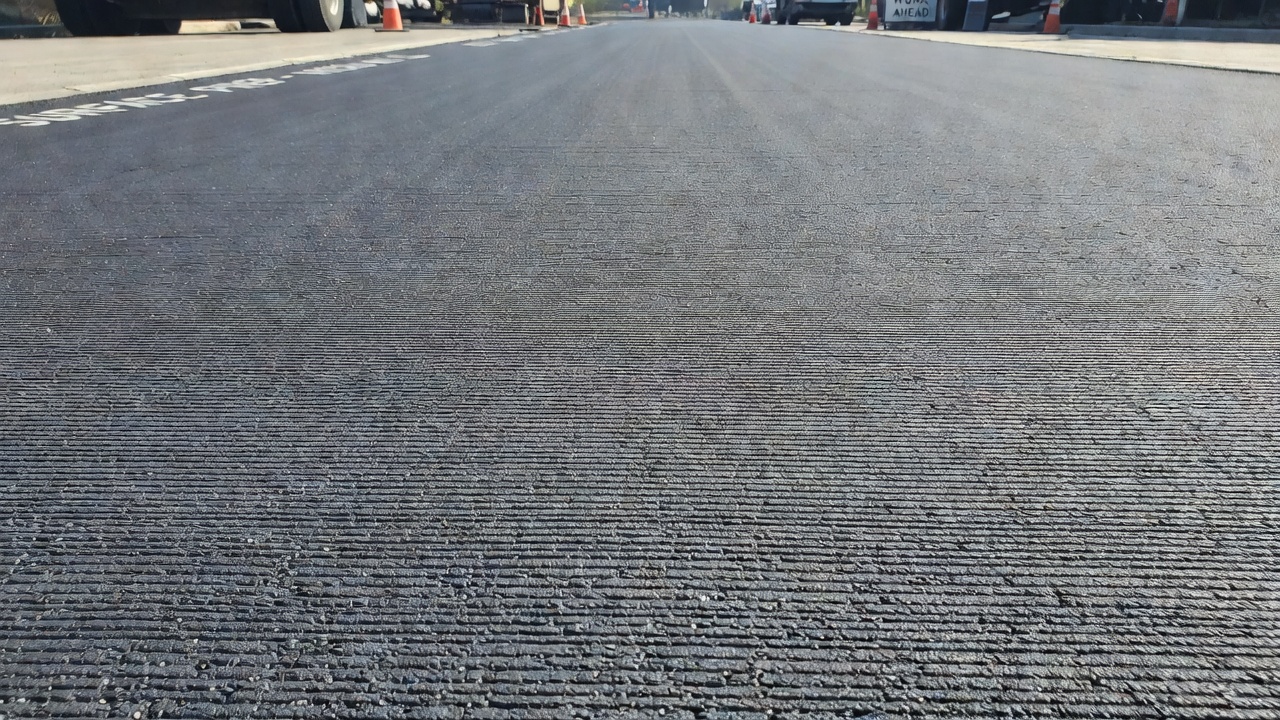
Cold planing prior to overlay placement is one of the most common pavement rehabilitation strategies worldwide. The process removes the distressed surface layer, restores the pavement profile, and provides a clean, textured substrate for bonding with the new overlay.
Surface Preparation for Overlay. The milled surface provides mechanical interlock between the existing pavement and the new hot mix asphalt overlay. The textured surface pattern increases the surface area available for bonding and provides a uniform substrate for tack coat application. The FAA Standard Specifications for Construction of Airports (AC 150/5370-10H) requires that existing pavement surfaces be prepared in accordance with the project plans and specifications prior to placement of new asphalt pavement.
Transition Areas. At the termination of each milling section and at ramp areas, transverse edges must be tapered at a minimum 10:1 (horizontal:vertical) taper rate. This means for every 25 mm (1 inch) of milling depth, the taper extends a minimum of 250 mm (10 inches) longitudinally. A minimum taper distance of 5 m (15 feet) is recommended for higher volume roadways. The taper ensures a smooth transition between the milled section and the adjacent unmilled pavement, preventing shock loading on vehicle suspension systems.
Longitudinal Joints. When milling half-lane passes, longitudinal vertical edges greater than 25 mm (1 inch) in height that are exposed to traffic must be beveled back at a minimum 3:1 ratio (75 mm horizontal for each 25 mm vertical). For safety, most state specifications require that a lane cannot be opened to traffic if the vertical joint between adjacent open lanes exceeds 50 mm (2 inches).
Temporary Traffic Surfaces. Milled surfaces can serve as temporary driving surfaces as long as the surface does not ravel. For lower volume roads, overlays are normally placed within 3-10 days. For high traffic volume roads, agencies increasingly require milling and resurfacing within the same shift before reopening to traffic. The milled surface must be maintained in a condition suitable for safe traffic movement, with all pavement markings restored before opening. Most agencies limit the duration of temporary traffic on milled surfaces to a maximum of 14 calendar days.
Temporary Transverse Tapers. Transverse joints at the end of each day’s milling operation require temporary ramps of asphalt mixture or cold planing tapers. The slope of the tapered joint shall be no less than 10:1 when open to traffic. If a temporary asphalt mixture ramp is used, the milled surface at the joint must be constructed as a butt joint for the full depth of the lift to be placed. The contractor is responsible for maintaining these asphalt ramps until all required lifts are placed.
Inspection of Milled Surface
Inspection of the milled surface is a quality assurance process that verifies compliance with project specifications. The inspection covers surface texture, profile tolerance, cross-slope uniformity, depth accuracy, and cleanliness.
Pre-Construction Inspection. Prior to beginning cold planing operations, the contractor must submit a Cold Planing Plan and a Quality Control Plan (QCP) for review. These plans must include:
Number, types, and sizes of cold planers
Width and location of each planing pass
Proposed method for planing around existing structures
Longitudinal and transverse typical sections for tie-ins
Schedule for replacing cutting teeth
Frequency of smoothness and macrotexture testing
Corrective procedures for non-conforming surfaces
In-Process Inspection. During the milling operation, the inspector verifies:
Depth of cut — measured from the milled surface to the original pavement surface at regular intervals
Surface texture — visual assessment for uniform striation pattern, absence of gouges or scalloped areas
Profile tolerance — using a 5 m (16 ft) or 3 m (10 ft) straightedge, all irregularities shall not exceed 6 mm (1/4 inch)
Cross-slope uniformity — no depressions or misalignment greater than 6 mm (1/4 inch) in 3.6 m (12 feet)
Cleanliness — milled surface free of dust, debris, and loose material before overlay placement
Scabbing — raveling or loose material that must be removed by additional milling
Defective Work. Distressed or irregular areas not meeting specification requirements shall be repaired in accordance with the contract documents. If scabbing occurs, the owner agency is notified. Scabbing caused by the operational speed of the cold planer (contractor responsibility) must be removed at the contractor’s expense. Scabbing caused by the condition of underlying layers is paid by force account.
Ride Quality Measurement. For milled surfaces on higher speed roadways, smoothness is measured using a road profiler or Maysmeter. A commonly used specification limits roughness to 900 mm/km on interstate routes and 1,000 mm/km on all other on-system routes. These end-result specifications allow contractors to select equipment and methods that meet the required finish, encouraging innovation in cutting tool technology and machine control systems.
Acceptance Criteria. The final acceptance of the milled surface is based on the following:
Visual — uniform texture, true to line, grade, and cross-section
Straightedge — irregularities not exceeding 6 mm (1/4 inch)
Cross-slope — no depressions or misalignment exceeding 6 mm (1/4 inch) in 3.6 m (12 feet)
Macrotexture — ratio of 1.8 or greater (when specified)
Smoothness — within specified profilograph or Maysmeter limits
Cleanliness — free of dust, debris, and loose particles
Cold Planing in Airport Pavement Rehabilitation
Cold planing is extensively used in airfield pavement rehabilitation projects under the framework of ICAO Annex 14, ICAO Doc 9157 Aerodrome Design Manual Part 3 — Pavements, and FAA Advisory Circular 150/5370-10H (Standard Specifications for Construction of Airports). The FAA specifications for airport construction reference cold planing through Item P-101 (Preparation of Existing Pavement Surfaces for Overlay) and Item P-102 (Removal of Existing Pavement).
Airfield-Specific Applications. Cold planing on airport pavements serves several critical functions:
Runway overlay preparation — milling existing runway surfaces to remove wheel-path rutting, corrugation, and thermal cracking before placing a new P-401 asphalt overlay
Cross-slope correction — restoring transverse slope on taxiways and aprons to meet ICAO and FAA drainage requirements, preventing water accumulation that could cause hydroplaning
Grade correction — correcting longitudinal profile deviations on runways to meet the operation level requirements for aircraft
Tie-in transitions — creating smooth 10:1 or flatter tapers at runway-to-taxiway junctions and pavement edge transitions
RAP removal for airside reuse — generating RAP that meets airport specifications for use in base courses or off-airway applications
FAA Specification Requirements. The FAA AC 150/5370-10H requires that pavement surfaces be prepared to the lines, grades, and cross-sections shown on the plans. The milled surface must provide a uniform texture suitable for the specified overlay thickness. The FAA also requires surface preparation to ensure positive drainage and prevent water accumulation on the milled pavement.
ICAO Guidance. ICAO Doc 9157 Part 3 provides guidance on pavement evaluation and rehabilitation, noting that cold planing is an appropriate method for correcting surface irregularities, restoring profile, and preparing pavement surfaces for structural overlay. The Aerodrome Design Manual emphasizes that surface evenness after cold planing must meet the operational safety requirements for aircraft operations, particularly with respect to:
Surface friction characteristics
Water drainage and hydroplaning prevention
Foreign Object Debris (FOD) prevention from raveling edges
Transition smoothness at pavement joints and interfaces
Airport Pavement Inspection. Airport pavement inspectors must verify that cold planing operations on airside pavements conform to:
Section depths shown on the plans, with particular attention to overlay design depth constraints
Surface macrotexture that provides adequate friction characteristics for aircraft operations
Joint and edge preparation that prevents FOD generation
Drainage improvements that prevent water ponding on runways and taxiways
Temporary surface condition that is safe for aircraft taxiing if the area remains operational
Micro-Milling for Surface Restoration
Micro-milling, also referred to as carbide grinding or fine milling, is a specialized cold planing process that produces an extremely fine, uniform surface texture suitable for use as a final riding surface or as preparation for thin surface treatments. Micro-milling was developed as a less expensive alternative to diamond grinding of concrete pavements and as a surface preparation method for slurry seals and microsurfacing on asphalt pavements.
Equipment Configuration. Micro-milling uses a standard cold planing machine fitted with a modified cutting drum where the cutting tools are spaced much closer together than in standard milling. Standard cold planing drums have approximately 165-175 cutting tools. Micro-milling drums carry 450-500 cutting tools with a spacing of 5-6 mm (0.2-0.25 inches) between tools on a typical triple-wrap configuration. The close tool spacing allows the drum to essentially grind every square inch of the milled surface, producing an exceptionally smooth, even texture.
Cutting Depth and Speed Limitations. Micro-milling is a surface treatment only and should not be used for deep asphalt removal. The maximum practical cutting depth is approximately 50 mm (2 inches). The forward speed of the milling machine must be strictly limited to achieve the desired surface finish. For a triple-wrap drum operating at 100 RPM cutter head speed, the recommended forward speed is approximately 9 m/min (30 ft/min). At this speed and tool spacing, the surface texture tolerance requires that the difference between high and low areas shall not exceed 2 mm (1/16 inch).
Benefits of Micro-Milling.
Corrects minor grade and profile problems economically
Removes wheel ruts up to 50 mm depth
Removes slick surfaces caused by binder bleeding
Increases skid resistance by re-cutting polished aggregate surfaces
Corrects drainage problems on localized areas
Produces a riding surface that can remain in service for extended periods
Reduces tire noise compared to standard milling texture
Provides an ideal bonding surface for slurry seals and microsurfacing
Improves ride quality economically, delaying the need for structural resurfacing
Applications. Micro-milling is performed prior to thin surface treatments including slurry seal, microsurfacing, and ultra-thin hot mix asphalt overlays. The process removes old, oxidized pavement and previous surface treatments, providing a clean, receptive surface for bonding. Micro-milling also produces clean, neat edges near gutters and concrete curbs. In addition to asphalt applications, micro-milling has been successfully used on Portland cement concrete pavements to improve ride quality, as demonstrated on the Indian Nation Turnpike in Oklahoma where several miles of concrete pavement were micro-milled a minimum of 6 mm (0.25 inch) all over and up to 50 mm (2 inches) at joints to improve the riding surface.
Specifications for Micro-Milling.
Drum tool spacing: 5-6 mm (0.2-0.25 inches) for triple-wrap configuration
Maximum depth of cut: 50 mm (2 inches)
Forward speed: approximately 9 m/min (30 ft/min) at 100 RPM cutter head speed
Surface texture tolerance: 2 mm (1/16 inch) maximum deviation
Straightedge tolerance: 3 m (10 ft) straightedge with profilograph smoothness
Macrotexture: verified by volumetric sand patch method
Distinction from Standard Cold Planing. The fundamental difference between cold planing and micro-milling is the texture produced on the pavement surface. Cold planing produces a coarse, striated texture suitable as a substrate for hot mix asphalt overlay but not as a final riding surface on high-speed roadways. Micro-milling produces a fine, closely spaced ribbed texture that provides excellent ride quality, low tire noise, and adequate skid resistance for use as a temporary or permanent riding surface without overlay. As noted by the LA County Department of Public Works, “Micro-milling provides for a smoother surface than cold milling and is typically used before a slurry seal or microsurfacing treatment.”
Key Specifications Summary
Parameter
Standard Cold Planing
Micro-Milling
Tool spacing
15 mm (5/8 in)
5-6 mm (0.2-0.25 in)
Number of tools
165-175 per drum
450-500 per drum
Max cutting depth
300 mm (12 in)
50 mm (2 in)
Surface tolerance
6 mm (1/4 in)
2 mm (1/16 in)
Forward speed at 100 RPM
20 m/min (66 ft/min)
9 m/min (30 ft/min)
Typical application
Overlay preparation
Final surface or thin treatment
Straightedge
5 m (16 ft)
3 m (10 ft)
Macrotexture ratio
≥ 1.8
≥ 1.8
Frequently Asked Questions
Cold planing (standard milling) uses a cutting drum with tool spacing of approximately 15 mm (5/8 inch) between teeth, producing a coarse textured surface with longitudinal striations. Micro-milling uses a drum with tools spaced 3-6 mm (1/8-1/4 inch) apart, typically 450-500 tools per drum versus 165-175 for standard milling. Micro-milling produces a very fine, uniform texture suitable for use as a final riding surface or as preparation for thin surface treatments like slurry seals. The maximum cutting depth for micro-milling is approximately 50 mm (2 inches), whereas standard cold planing can remove up to 300 mm (12 inches) in a single pass.
Yes, cold planing machines are capable of milling both asphalt and Portland cement concrete (PCC) pavements. However, milling concrete generates significantly more wear on cutting tools due to the hardness and abrasiveness of the aggregate and cement matrix. Tool life on concrete milling can be reduced to one hour or less compared to several days on asphalt. Special carbide-tipped or diamond-tipped tools are often used for concrete milling applications. The process is commonly used to remove surface irregularities at concrete pavement joints, restore cross-slope on concrete runways, and prepare concrete surfaces for asphalt overlays (whitetopping or bonded overlays).
The macrotexture of a milled pavement surface is measured using a sand patch test (volumetric technique) or laser profilometer. The most common specification requires that the difference between the high and low points of the milled surface shall not exceed 6 mm (1/4 inch) when measured with a 3 m (10 ft) or 5 m (16 ft) straightedge. For micro-milling, the tolerance is reduced to 2 mm (1/16 inch). The Indiana DOT Test Method ITM No. 812-13T specifies macrotexture testing using glass beads, requiring a macrotexture ratio of 1.8 or greater. The forward speed of the milling machine must not exceed two-thirds of the cutter drum RPM to maintain adequate texture quality.
Cold planing effectively treats the following asphalt pavement distresses: rutting (wheel path depressions), raveling (aggregate loss), bleeding (excess binder on surface), corrugations and shoving, deteriorated or aged asphalt, stripping (loss of binder-aggregate bond), and ride quality issues such as swells, bumps, sags, and depressions. Cold planing removes the distressed layer to a depth that exposes sound material, providing a clean, uniform surface for overlay placement. The process also corrects profile irregularities including ponding areas, curb reveal problems, and shoulder drop-off issues.
When a milled surface is opened to temporary traffic, several safety requirements apply. Longitudinal vertical joint edges greater than 25 mm (1 inch) in height must be beveled back at a 3:1 (horizontal:vertical) ratio. Transverse vertical edges with greater than 12.5 mm (1/2 inch) drop-off require temporary asphalt tie-ins with a minimum 10:1 taper rate. The milled surface must not trap or hold water. Pavement markings removed by planing must be restored before opening to traffic. State specifications typically require that the vertical joint between adjacent open lanes not exceed 50 mm (2 inches) for safety. Most agencies limit the duration of temporary traffic on milled surfaces to a maximum of 14 calendar days.
Need Airfield Pavement Inspection Services?
TarmacView provides expert airfield pavement condition surveys including milled surface quality inspection, transition area evaluation, and overlay preparation assessments. Contact our team to schedule an inspection.
Cold In-Place Recycling (CIR) of Asphalt Pavements
Cold In-Place Recycling (CIR) is a pavement rehabilitation method where existing asphalt layers are milled, mixed with recycling agents (emulsion or foamed asph...
Hot In-Place Recycling (HIR) rehabilitates asphalt pavements on-site by heating, scarifying, and remixing the existing surface (sometimes adding rejuvenator and...
Leveling Course in Asphalt Pavement Rehabilitation
A leveling course is a variable-thickness asphalt layer placed on an existing pavement to correct profile irregularities (rutting, settlement, cross-section def...
29 min read
Pavement rehabilitation
Asphalt overlay
+2
Cookie Consent We use cookies to enhance your browsing experience and analyze our traffic. See our privacy policy.