Concrete cover is the minimum depth of concrete between the outer surface and the nearest reinforcing steel, providing corrosion protection through physical barrier, high pH passivation, and fire resistance. Inadequate cover is a primary cause of premature rebar corrosion. Cover requirements span ACI 318, AASHTO LRFD, Eurocode 2, and FAA/ICAO standards.
Concrete Cover for Reinforcement Protection
Definition and Purpose of Concrete Cover
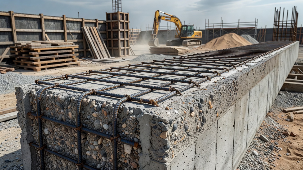
Concrete cover is defined as the minimum distance measured from the outer surface of a concrete element to the outermost surface of the nearest reinforcing steel. This dimension, also referred to as clear cover or reinforcement cover, is the single most important geometric parameter governing the long-term durability of reinforced concrete structures. It is distinct from the total concrete section thickness, focusing exclusively on the protective layer between the environment and the embedded steel.
The concrete cover serves three distinct and equally critical functions in reinforced concrete design. The first and most widely recognized function is corrosion protection. The cover concrete maintains a high-alkaline environment with a pH typically ranging from 12.5 to 13.5, sustained by calcium hydroxide (Ca(OH)₂) and other hydration products in the cement paste. This alkalinity causes the formation of a stable, nanometer-thin passive film of gamma iron oxide (γ-Fe₂O₃) on the steel surface. This passive film renders the steel immune to corrosion under normal conditions. Simultaneously, the cover acts as a physical barrier that impedes the transport of chlorides, carbon dioxide (CO₂), oxygen, and moisture from the external environment toward the reinforcement. The depth and quality of this barrier directly determine the time required for aggressive agents to reach the steel and initiate corrosion.
The second function is fire resistance. The cover concrete provides thermal insulation to the reinforcing steel during fire exposure. When reinforced concrete members are subjected to elevated temperatures, the steel reinforcement loses strength rapidly above approximately 400°C. The insulating effect of the concrete cover delays the temperature rise in the steel, preserving load-carrying capacity for a longer duration. Fire resistance ratings for reinforced concrete members — expressed as standard fire periods of 30, 60, 90, or 120 minutes — are directly correlated with cover dimensions. ACI 216.1 and Eurocode 2 Part 1-2 specify minimum cover values required for different fire resistance ratings, ranging from 20 mm for 30-minute ratings up to 60 mm for 240-minute ratings in beams and slabs.
The third function is bond strength and stress transfer. Adequate concrete cover around reinforcing bars is essential for developing the bond stresses that transfer forces between the steel and surrounding concrete. The bond mechanism relies on three components: chemical adhesion, frictional resistance, and mechanical interlock between the bar deformations (ribs) and the surrounding concrete. When the cover is insufficient, the concrete surrounding the bar can fail in splitting tension before the full yield strength of the steel is developed. The development length equations in ACI 318 (Section 25.4) incorporate cover terms explicitly: bars with greater cover have shorter required development lengths because the confining concrete resists splitting forces more effectively. For example, a No. 8 bar in normal-weight concrete with 3 inches of cover has approximately 20% shorter development length than the same bar with 1.5 inches of cover.
Cover Requirements by Exposure and Code
ACI 318 Minimum Cover Requirements
The American Concrete Institute Building Code Requirements for Structural Concrete (ACI 318-19, Section 20.6) establishes the minimum concrete cover for cast-in-place nonprestressed concrete based on exposure condition, reinforcement bar size, and structural element type. The code recognizes that exposure to weather, earth contact, and corrosive environments demands greater protection. The exposure classifications in ACI 318 that influence cover include exposure classes for corrosion protection of reinforcement (C0, C1, C2) and exposure classes for freeze-thaw (F0, F1, F2, F3).
For concrete cast against and permanently exposed to earth, ACI 318 requires a minimum cover of 75 mm (3 inches) regardless of bar size. For concrete exposed to earth or weather but not cast against earth, the requirement varies by bar size: 50 mm (2 inches) for #6 through #18 bars and 38 mm (1.5 inches) for #5 and smaller bars. For concrete not exposed to weather or earth contact, the requirements are reduced: 19 mm (0.75 inches) for #11 and smaller bars in slabs, walls, and joists; 38 mm (1.5 inches) for #14 and #18 bars in slabs, walls, and joists; and 38 mm (1.5 inches) for beams and columns of all bar sizes.
For structures in severe or very severe corrosion exposure (C2 class per ACI 318), additional cover is required. This typically increases cover by 13 mm (0.5 inches) beyond the base values. For concrete exposed to chlorides from deicing salts, seawater, or industrial processes, ACI 318.2 specifies minimum cover of 63 mm (2.5 inches) for bridge decks and other elements. For structures requiring 100-year service life, many owners further increase cover to 75 mm (3 inches).
AASHTO LRFD Bridge Design Specifications
The AASHTO LRFD Bridge Design Specifications establish minimum cover requirements for bridge superstructures and substructures. For bridge decks, which are among the most corrosion-critical elements due to deicing salt exposure, the minimum cover to the top reinforcement is 63 mm (2.5 inches) . The bottom mat requires 25 mm (1 inch) cover. For bridge substructures (columns, pier caps, abutments), cover varies from 50 mm (2 inches) in moderate environments to 75 mm (3 inches) in severe environments exposed to salt spray or deicing chemicals.
AASHTO also requires that cover dimensions account for the placement tolerances expected during construction. The specified cover in contract documents is the minimum permitted, and actual measured cover must exceed these values. For high-performance concrete (HPC) bridge elements, AASHTO acknowledges that the reduced permeability may justify modified cover requirements, though the standard approach remains to use specified minimum values with supplementary corrosion protection measures when reduced cover is proposed.
Eurocode 2 (EN 1992-1-1) Cover Requirements
Eurocode 2 defines concrete cover using a different framework than ACI 318, based on nominal cover (cₙₒₘ) , which is the sum of the minimum cover (cₘᵢₙ) and an allowance for deviation (Δc_dₑᵥ) , typically 10 mm. The minimum cover is calculated as the maximum of three values: cover required for bond (cₘᵢₙ,ᵦ), cover required for environmental exposure durability (cₘᵢₙ,ₔᵤᵣ), and an absolute minimum of 10 mm.
The environmental exposure classification in Eurocode 2 is more granular than ACI 318, using exposure classes X0 (no risk), XC1–XC4 (carbonation-induced corrosion), XD1–XD3 (chloride-induced corrosion from non-seawater sources), XS1–XS3 (chloride-induced corrosion from seawater), and XF1–XF4 (freeze-thaw attack). For carbonation exposure class XC1 (permanently wet concrete), minimum cover for bond governs at approximately 15 mm for slabs and 20 mm for beams in structural class S4. For XC4 (cyclic wet and dry, typical of exterior structures), minimum cover for durability governs at values ranging from 30 mm (structural class S4, 50-year design life) to 45 mm (structural class S6, 100-year design life). For the most severe chloride exposure class XD3 or XS3 (tidal and splash zones), minimum cover reaches 55 mm for 50-year design life and 65 mm for 100-year design life.
The structural class (S1 through S6) in Eurocode 2 adjusts the cover requirements based on design working life, concrete quality, and element geometry. A reduction of one structural class is permitted when the concrete compressive strength class exceeds C30/37, when the element is a slab (less critical for bond), or when special quality control measures are implemented.
Exposure Class
Carbonation Risk
Min Cover S4 50yr (mm)
Min Cover S6 100yr (mm)
X0
No risk
15
25
XC1
Dry/permanently wet
15
25
XC2
Wet, rarely dry
25
35
XC3
Moderate humidity
25
35
XC4
Cyclic wet/dry
30
45
XD1/XS1
Moderate humidity chlorides
40
55
XD2/XS2
Wet chlorides
45
60
XD3/XS3
Cyclic wet/dry chlorides
45
65
Cover Requirements by Structural Element Type
Cover requirements vary significantly by structural element type because of differences in exposure severity, casting position, and consequences of cover deficiency.
Slabs generally require the least cover because they are typically cast with the reinforcement in the bottom portion where concrete placement and consolidation are easier. For interior slabs not exposed to weather, ACI 318 permits cover as low as 19 mm (0.75 inches) for #11 and smaller bars. However, slab-on-grade construction requires minimum 50 mm (2 inches) cover because of earth contact. Bridge decks require the most stringent cover, with 63 mm (2.5 inches) typical for top reinforcement.
Beams require greater cover than slabs because of their exposure to three-sided environmental attack and the more critical structural consequences of corrosion in flexural tension reinforcement. ACI 318 requires 38 mm (1.5 inches) minimum cover for beam reinforcement not exposed to weather. For beams exposed to weather or corrosive environments, this increases to 50 mm (2 inches) for larger bars.
Columns require 38 mm (1.5 inches) minimum cover per ACI 318 for interior applications, increasing to 50 mm (2 inches) for exposed columns. Column ties must have the same cover as main longitudinal reinforcement because they provide shear resistance and confinement.
Foundations cast against earth require 75 mm (3 inches) minimum cover per ACI 318, which is the highest standard base requirement. This accounts for the moisture presence in soil, potential chemical attack from groundwater, and the difficulty of inspection after backfilling.
Precast concrete elements manufactured under plant-controlled conditions can have reduced cover because of higher quality control, better consolidation, and controlled curing. Eurocode 2 permits reducing nominal cover by the deviation allowance (Δc_dₑᵥ) or one structural class for plant-produced elements.
Cover and Corrosion Initiation Time
The relationship between concrete cover depth and corrosion initiation time follows principles of mass transport and chemical threshold phenomena. Corrosion of steel in concrete begins when either the passive film is destroyed by chloride accumulation above a threshold concentration, or the pH at the steel depth drops below approximately 9 due to carbonation. In both cases, the cover depth determines the time required for the aggressive agent to reach the reinforcement.
The time to corrosion initiation (tᵢ) for chloride-induced corrosion is modeled using Fick’s second law of diffusion. The chloride concentration at depth x and time t is given by C(x,t) = Cₛ [1 - erf (x / 2√(D·t))], where Cₛ is the surface chloride concentration, D is the apparent chloride diffusion coefficient, and erf is the Gaussian error function. Setting C(x,t) equal to the critical chloride threshold (typically 0.05–0.10% by concrete weight for conventional steel) and solving for t at x = cover depth gives the initiation time. This relationship is highly sensitive to cover: doubling the cover depth increases the initiation time by approximately a factor of four, all other parameters being equal.
For carbonation-induced corrosion, the carbonation depth (d_c) is typically modeled using the square-root-of-time relationship: d_c = k·√t, where k is the carbonation coefficient (typically 3–8 mm/√year for normal concrete). The time for the carbonation front to reach the steel is tᵢ = (cover/k)². A concrete cover of 30 mm with a carbonation coefficient of 5 mm/√year provides 36 years to carbonation-induced corrosion initiation. Reducing the cover to 15 mm reduces initiation time to just 9 years under the same conditions.
Field studies consistently demonstrate the critical importance of cover depth. Surveys of marine bridge structures by the Florida Department of Transportation found that elements with cover less than 50 mm showed active corrosion after 15–25 years of service, while elements with cover greater than 75 mm remained corrosion-free beyond 40 years. The UK Highways Agency research on bridge decks showed that a 10 mm reduction in cover below specification typically reduced service life by 30–50%, confirming that cover is the most influential design parameter for durability under chloride exposure.
Cover Measurement Techniques
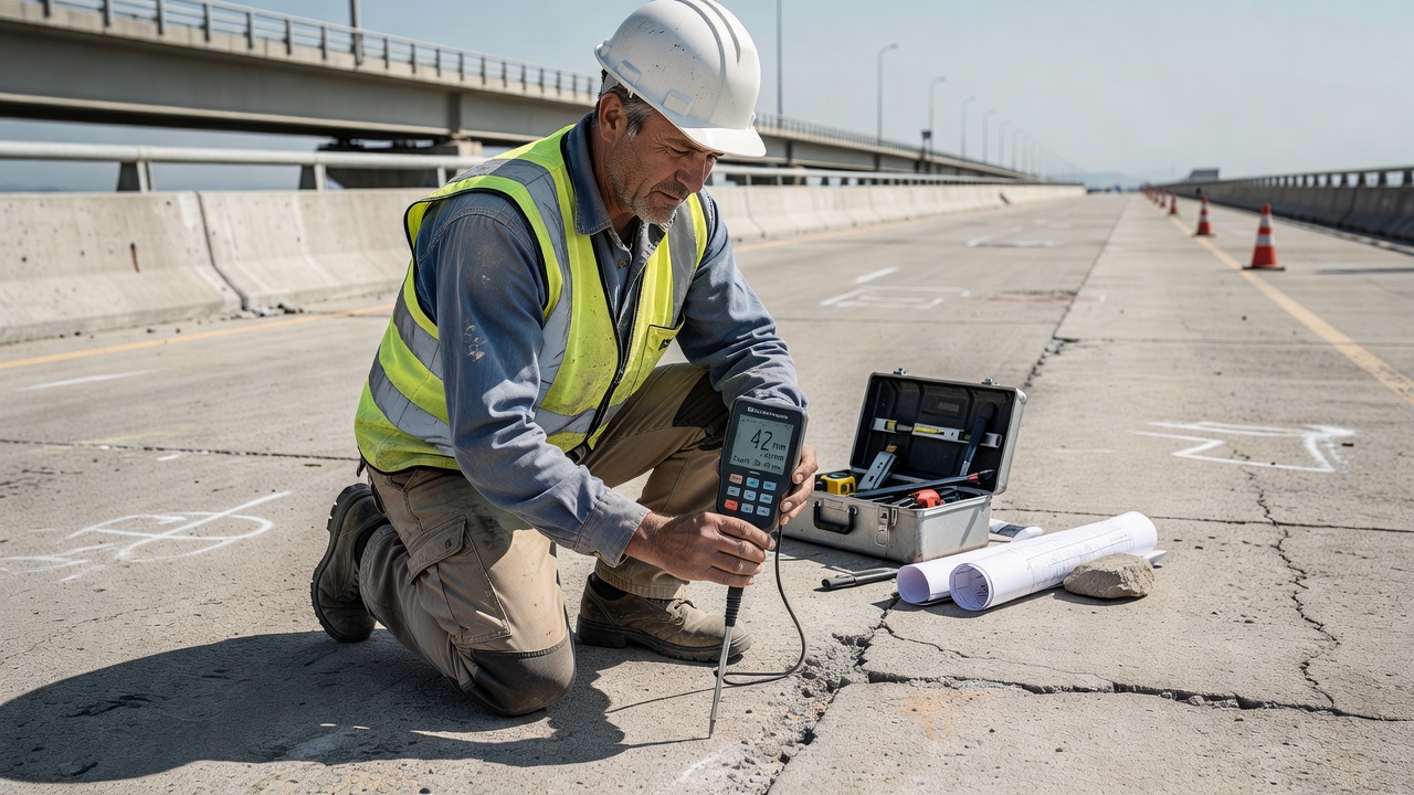
Cover Meters (Pachometers)
The cover meter, also called a pachometer or rebar locator, is the most widely used non-destructive testing instrument for measuring concrete cover depth. The operating principle is based on electromagnetic induction. An alternating current in the probe coil generates an alternating magnetic field. When this field encounters a reinforcing bar, eddy currents are induced in the steel, creating a secondary magnetic field that alters the impedance of the probe coil. The change in impedance is proportional to the distance to the steel and the bar diameter.
Modern cover meters such as the Proceq Profometer PM8000 and Hilti PS 200 operate across a measurement range of 0–120 mm (approximately 0–4.7 inches) with accuracy of ±1–3 mm depending on conditions. Advanced instruments incorporate neighboring rebar correction (NRC) technology that automatically compensates for the influence of adjacent reinforcement bars, which is critical for accurate measurement in congested reinforcement. Without NRC, cover measurements over secondary bars can be in error by 20 mm or more due to magnetic interference from deeper primary reinforcement.
The measurement procedure involves slowly sweeping the probe across the concrete surface perpendicular to the expected bar alignment. The instrument displays real-time cover depth and typically provides an audible signal when the probe is directly over the bar. Data logging capabilities allow mapping of cover across entire structural elements, producing cover contour plots that identify areas outside specification tolerance. ASTM E2632 is the standard test method for evaluating cover meter performance.
Cover meter limitations include: measurement depth limited to approximately 120 mm; degraded accuracy when the bar diameter is unknown; interference from magnetic aggregates, nearby ferrous objects, and closely spaced bars; and inability to measure cover over non-ferrous reinforcement (e.g., GFRP bars).
Ground Penetrating Radar (GPR)
Ground penetrating radar provides an alternative cover measurement technique, particularly valuable when reinforcement is too deep for conventional cover meters, when the cover exceeds 120 mm, or when full-area scanning is required. GPR operates by transmitting electromagnetic pulses into the concrete and recording the reflections from embedded objects and layer interfaces. The two-way travel time of the radar pulse, combined with the known dielectric permittivity of concrete, allows calculation of depth.
For cover measurement applications, GPR antennas in the 1.5–4.0 GHz frequency range are preferred. Higher frequencies provide better resolution for thin cover layers but reduced penetration depth. The 2.6 GHz antenna used in systems like the GSSI StructureScan Mini XT offers approximately 40 mm resolution in cover depth measurement with penetration to 450 mm. Lower frequency antennas (900 MHz–1.5 GHz) can penetrate to 800 mm but with reduced accuracy for shallow cover.
GPR offers the advantage of continuous scanning along survey lines, producing radargrams (B-scans) that show the hyperbolic reflection patterns characteristic of rebar. The analysis allows simultaneous determination of cover depth, bar spacing, and bar count. However, GPR accuracy depends critically on the dielectric constant of the concrete, which varies with moisture content, density, and aggregate type. Inaccuracies in dielectric calibration can produce ±5 mm or greater errors. GPR also requires significant operator training and post-processing analysis using software such as RADAN (GSSI).
A comparative study published in Građevinar (2021) comparing cover meter and GPR performance across nine case studies found that cover meters provide superior accuracy for cover depths under 80 mm (±1–3 mm), while GPR offers advantages for deeper cover assessment and large-area coverage. The choice between methods depends on cover depth, reinforcement density, required accuracy, and the purpose of the investigation.
Destructive Verification
When NDT methods produce questionable results or when legal verification is needed, direct measurement through localized concrete removal is the definitive method. This involves exposing the reinforcement by chipping away the cover concrete in small patches (typically 50 mm diameter), measuring the distance directly with a depth gauge, and subsequently repairing the opening with a structural repair mortar per ASTM C928. While destructive, it provides absolute verification that can be used to calibrate NDT instruments for subsequent non-destructive surveying.
Consequences of Insufficient Cover
Insufficient concrete cover is the single most common design or construction deficiency leading to premature reinforcement corrosion and concrete deterioration. The consequences cascade through multiple mechanisms and manifest at progressively severe levels.
Plastic settlement cracking is the earliest consequence of insufficient cover. When cover is thin, the embedded reinforcement acts as a restraint to the vertical settlement of fresh concrete after placement. Cracks form over the bar lines as the concrete settles around the bars. This cracking is visible within hours of placement and provides direct pathways for moisture and chlorides to reach the steel, bypassing the intended protection of the cover.
Accelerated carbonation follows as the second consequence. Carbon dioxide from the atmosphere diffuses through the cover concrete faster through thinner sections. The carbonation reaction converts calcium hydroxide to calcium carbonate, reducing the pore solution pH from approximately 12.5 to below 9. At this pH level, the passive film on steel is no longer stable, and general corrosion initiates across the entire bar surface. The carbonation depth in normal concrete follows the square root of time, so a 15 mm cover in a 30 MPa concrete with moderate water-cement ratio may carbonate fully within 5–10 years in urban environments.
Chloride-induced pitting corrosion is the most aggressive consequence when insufficient cover coincides with chloride exposure. Chloride ions from deicing salts, seawater, or industrial environments penetrate the concrete through diffusion, capillary absorption, and hydrostatic pressure. When the chloride concentration at the steel depth exceeds the threshold level (typically 0.4–1.0% by weight of cement , or approximately 0.05–0.15% by weight of concrete, depending on cement type, pH, and steel potential), localized breakdown of the passive film initiates pitting corrosion. The pits create highly localized anodes with extremely high current densities, leading to deep metal section loss while the surrounding steel remains apparently sound.
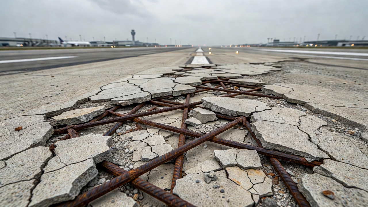
Corrosion-induced cracking and spalling represents the visible structural consequence. The corrosion products (ferrous hydroxide, ferric hydroxide, goethite, lepidocrocite, and magnetite) occupy 2–6 times the volume of the original steel consumed. This volumetric expansion generates tensile hoop stresses in the surrounding concrete. When these stresses exceed the tensile strength of concrete (typically 2–5 MPa), radial cracks propagate from the bar to the surface. Continued corrosion widens these cracks and leads to spalling — the detachment of concrete fragments around the bar line. The spalled areas further accelerate deterioration by exposing fresh concrete to the environment and reducing the effective structural section.
Structural capacity reduction follows from the combined effects of steel section loss, concrete section loss, and bond degradation. A 10% loss of steel cross-section due to uniform corrosion reduces the moment capacity of a typical beam by approximately 8–10%. Pitting corrosion can cause a 20% reduction in bar cross-section locally while appearing minor in overall weight loss, creating stress concentrations that precipitate sudden failure under load. Bond strength degradation is particularly severe when cover is lost through spalling, as the confinement essential for bond transfer is eliminated.
Airport-specific hazards of insufficient cover include Foreign Object Debris (FOD) generation from spalled concrete fragments on runways and taxiways. Exposed reinforcement at pavement joints and edges creates tripping hazards and tire puncture risks for aircraft. The FAA Advisory Circular 150/5370-10 specifies strict cover requirements for airfield pavements: 75 mm (3 inches) minimum cover for concrete pavement reinforcement, increased from previous 50 mm requirements. ICAO Annex 14 references ACN/PCN reporting systems that indirectly account for pavement condition, with cover deficiency being a major factor in pavement condition deterioration.
Cover in Airport Concrete Structures
Concrete cover requirements for airport pavements are among the most stringent in civil engineering because of the extreme consequences of surface deterioration in an operational airfield environment. The FAA and ICAO establish cover standards through multiple documents.
The FAA Advisory Circular 150/5370-10H (Standard Specifications for Construction of Airports) establishes minimum concrete cover for airfield pavements at 75 mm (3 inches) for continuously reinforced concrete pavement (CRCP) and jointed plain concrete pavement (JPCP) containing steel reinforcement. This value reflects the extremely aggressive exposure conditions: aircraft deicing chemicals (including potassium acetate, sodium acetate, and urea-based compounds), jet fuel spills, hydraulic fluid leaks, freeze-thaw cycling, and heavy dynamic loading that accelerates microcracking and transport mechanisms.
The U.S. Army Corps of Engineers UFC 3-260-01 (Airfield and Heliport Planning and Design) specifies that concrete cover over the top reinforcement in airfield pavements shall be 75 mm (3 inches) minimum, with cover over bottom reinforcement of 50 mm (2 inches) minimum for dowel bars at joints and 38 mm (1.5 inches) for continuous reinforcement in slabs supporting 12.5 metric ton aircraft. These values increase by 13 mm when the pavement is exposed to deicing chemicals.
ICAO Aerodrome Design Manual Part 3 — Pavements (Doc 9157) provides guidance on pavement design standards but defers specific cover values to national standards. The manual emphasizes that the concrete cover must be adequate to protect reinforcement against corrosion induced by deicing chemicals, and recommends a minimum cover of 70 mm for reinforced concrete pavements in areas subject to deicing operations. The manual also stresses that joint sealants and waterstops at pavement joints should not reduce the effective cover at joints, which are the most corrosion-vulnerable locations in airfield pavements.
The Transportation Security Administration (TSA) and airport authorities increasingly recognize that insufficient cover detection should be incorporated into Pavement Condition Index (PCI) surveys conducted per ASTM D5340. The correlation between low cover and pavement surface distresses — especially joint spalling, corner breaks, and punchouts — means that cover assessment should be part of comprehensive pavement evaluation programs. TarmacView’s AI-driven inspection platform addresses this need by detecting areas of exposed reinforcement and insufficient cover through advanced computer vision analysis of pavement surface images, enabling airport operators to prioritize repair of cover-deficient areas before they develop into full FOD hazards.
Cover Inspection and Assessment
Inspection of concrete cover in existing structures follows systematic procedures defined by ACI 228.2R (Nondestructive Test Methods for Evaluation of Concrete in Structures) and RILEM TC 127-TENR. The assessment typically proceeds through three phases: desk study, site investigation, and data analysis.
The desk study phase reviews design drawings, construction records, and inspection reports to identify the specified cover values for each structural element type. This establishes the acceptance criteria against which field measurements are compared. Any variation between contract documents and actual as-constructed cover is flagged for investigation.
The site investigation phase begins with calibration of cover measurement instruments using reference samples of known cover depth and bar diameter. ASTM E2632 requires calibration verification before and after each survey session. Measurement grids are established on structural elements at spacings of 300–500 mm for detailed surveys and 500–1000 mm for screening surveys. Each measurement point is marked, and the cover reading is recorded along with bar detection indication. Modern instruments connect to tablet computers via Bluetooth for real-time data logging and GPS-coordinated mapping.
The data analysis phase involves statistical evaluation of cover measurements against specified values. ACI 214.4R provides guidance on interpreting cover test results. The acceptance criteria typically require that 90% of measured cover values exceed the specified minimum, and no individual measurement is less than the specified minimum minus 6 mm (0.25 inches). The data distribution is analyzed to identify systematic low cover, which may indicate improperly assembled reinforcement cages, displaced formwork, inadequate wheel spacers or bar chairs, or missing cover blocks.
Assessment also considers cover quality in addition to cover quantity. A cover depth meeting specification but consisting of porous, poorly consolidated, or cracked concrete provides inadequate protection. The quality of the cover concrete depends on water-cement ratio, degree of compaction (consolidation), curing effectiveness, and the presence of plastic settlement cracks or honeycombing. Cover quality is assessed through a combination of air permeability testing (Torrent permeability method), water absorption testing (Initial Surface Absorption Test — ISAT), and near-surface strength assessment (pull-off testing per ASTM C1583).
Remediation for Low Cover
When cover measurements reveal insufficient cover, remediation options depend on the severity of the deficiency, the exposure conditions, the structural role of the element, and the cost-benefit analysis of available options.
Hydrogel Permeability Reduction Treatment
Penetrating hydrogel treatments offer a practical and cost-effective solution for low cover remediation. Products such as AQURON 2000 and AQURON 7000 are spray-applied, water-based formulations containing silicate-based compounds that react with calcium hydroxide in the concrete pore structure to form a crystalline hydrogel within the capillary network. This reduces permeability by over 100% as measured by water absorption testing. Independent studies have shown that hydrogel treatment can effectively double the equivalent cover of the concrete. For example, a real cover depth of 20 mm treated with penetrating hydrogel has the protective equivalence of 40 mm of untreated cover. Research indicates an equivalence factor of 2.0 is conservative for concrete with compressive strength up to 50 MPa.
The advantages of hydrogel treatment include minimal downtime (approximately 1 hour before water exposure), no change to structural dimensions or appearance, and application by conventional spray equipment. The treatment penetrates to a depth of 15–40 mm depending on concrete porosity and moisture content. This option is particularly suitable for large-area low cover deficiencies where other remediation methods are impractical.
Cementitious and Polymer Coatings
Cementitious surface coatings such as Flexcrete Cementitious Coating 851 provide an alternative approach by applying a thin polymer-modified cement layer to the concrete surface. Independent testing has demonstrated that a 2 mm coating of cementitious coating is equivalent to 100 mm of good quality concrete cover in terms of chloride diffusion resistance. These coatings provide a complete barrier to water under 10 bar pressure and react chemically with the substrate to form an integral bond. Testing at the VINCI Construction Technology Centre showed no detectable steady-state chloride ion flux through the coating after 24 years of exposure, while the control concrete reached steady-state chloride transmission in 28 days.
Cementitious coatings are applied by brush or spray in one or two coats. They can be color-matched to the parent concrete, making them cosmetically acceptable for visible surfaces. The coatings are CE-marked to BS EN 1504 (Products and Systems for the Protection and Repair of Concrete Structures) and have demonstrated performance on structures worldwide, including the West Kowloon Expressway viaduct leading to Hong Kong International Airport, where low cover was detected on precast segments during construction.
Cathodic Protection
For existing structures where insufficient cover has already led to active corrosion, cathodic protection (CP) provides electrochemical corrosion control. Impressed current cathodic protection (ICCP) systems use a low-voltage DC power supply connected between an inert anode (typically mixed metal oxide titanium mesh or conductive coating) on the concrete surface and the reinforcing steel acting as the cathode. The applied current forces the steel potential below the corrosion threshold, stopping all corrosion activity regardless of cover depth.
Sacrificial anode cathodic protection uses zinc or aluminum anodes bonded to the concrete surface or embedded in repair patches. Thermal-sprayed zinc anodes have been applied to bridge substructures with low cover to provide corrosion protection without removing sound concrete. The Florida Department of Transportation has used this approach extensively on marine bridges where insufficient cover has been identified.
Concrete Replacement and Overlay
For localized low cover areas, concrete removal and replacement is the definitive remediation. The low-cover concrete is removed using high-pressure water lancing (hydrodemolition) or mechanical chipping to a depth of at least 20 mm behind the reinforcement. Formwork is repositioned to achieve the specified cover, and the section is recast with either conventional concrete or a shrinkage-compensating repair mortar. For bridge decks, concrete overlay with a microsilica-modified concrete provides an additional 40–75 mm of cover while renewing the wearing surface.
This approach is expensive and disruptive but provides a permanent restoration condition. For precast concrete elements with identified low cover, acceptance or rejection decisions at the plant are preferred over field remediation, leading to immediate replacement rather than repair. However, once elements are installed and integrated into the structure, full-depth replacement is rarely practical, and alternative remediation methods are preferred.
Design Phase Prevention
The most effective approach to low cover is prevention through proper design detailing and construction quality control. Designers should provide adequate tolerance margins — a specified cover of 38 mm with a construction tolerance of ±6 mm leaves zero acceptable margin. Specifying cover at 50 mm for weather-exposed slabs when the code minimum is 38 mm provides more realistic targets.
Construction measures include: using plastic bar chairs and wheel spacers at maximum 600 mm spacing to support reinforcement at the design depth; increasing chair density at construction joints and slab edges where displacement is most likely; verifying cover with profiled depth gauges before concrete placement; inspecting for formwork displacement during the pour; and performing post-placement cover surveys on completed elements to identify deficiencies early.
Summary of Key Cover Values by Code and Application
Standard
Element / Exposure
Minimum Cover
ACI 318-19
Cast against/ever exposed to earth
75 mm (3 in)
ACI 318-19
Exposed to weather — #6 to #18 bars
50 mm (2 in)
ACI 318-19
Exposed to weather — #5 and smaller
38 mm (1.5 in)
ACI 318-19
Slabs/walls not exposed — #11 and smaller
19 mm (0.75 in)
ACI 318-19
Beams/columns not exposed
38 mm (1.5 in)
AASHTO LRFD
Bridge deck top reinforcement
63 mm (2.5 in)
AASHTO LRFD
Bridge deck bottom reinforcement
25 mm (1 in)
AASHTO LRFD
Substructure — severe exposure
75 mm (3 in)
Eurocode 2 XC4
Exterior structures — 100yr S6
45 mm
Eurocode 2 XD3/XS3
Tidal/splash zone — 100yr S6
65 mm
FAA AC 150/5370-10H
Airport concrete pavement
75 mm (3 in)
UFC 3-260-01
Airfield pavement top steel
75 mm (3 in)
Conclusion
Concrete cover is the most critical parameter for ensuring the long-term durability and structural integrity of reinforced concrete. It serves as the primary defense against reinforcement corrosion through physical barrier, chemical passivation, and fire insulation functions. Cover requirements established by ACI 318, AASHTO, Eurocode 2, and FAA/ICAO standards reflect exposure severity, element type, and design service life. Field measurement using cover meters and GPR provides essential quality assurance for new construction and condition assessment for existing structures. When insufficient cover is identified, remediation options ranging from hydrogel treatments and surface coatings to cathodic protection and concrete replacement provide a tiered approach to restoring protective function. In airport environments where the safety consequences of exposed reinforcement include FOD hazards and structural degradation, rigorous cover specification, verification, and remediation programs are essential for maintaining operational safety and extending pavement service life.
Frequently Asked Questions
Concrete cover is the minimum distance between the outer surface of a concrete element and the nearest surface of the reinforcing steel. It protects the steel from corrosion by maintaining a high-pH passivation environment, provides fire resistance through thermal insulation, and ensures adequate bond transfer between the concrete and reinforcement. Cover depth is specified by building codes based on exposure conditions, structural element type, and reinforcement bar size.
ACI 318-19 Section 20.6 specifies minimum cover for cast-in-place nonprestressed concrete: 3 inches (75 mm) for concrete cast against and permanently exposed to earth; 2 inches (50 mm) for #6 through #18 bars exposed to earth or weather; 1.5 inches (38 mm) for #5 and smaller bars exposed to earth or weather; 0.75 inches (19 mm) for #11 and smaller bars in slabs, walls, joists not exposed to weather; 1.5 inches (38 mm) for beams and columns not exposed to weather; and 0.75 inches (19 mm) for shells and folded plate members with #6 and larger bars. These values increase for corrosive environments and severe exposure classes.
Concrete cover prevents reinforcement corrosion through three mechanisms. First, it provides a physical barrier that delays the ingress of chlorides, carbon dioxide, moisture, and oxygen to the steel surface. Second, the highly alkaline pore solution (pH 12.5–13.5) in concrete creates and maintains a passive iron oxide film on the steel surface that prevents corrosion initiation. Third, the cover depth determines the time required for aggressive agents to reach the steel — a thicker cover extends this initiation period. Corrosion begins when chlorides accumulate above the threshold level (typically 0.05–0.1% by weight of concrete for chlorides) or when carbonation reduces the pH below approximately 9 at the steel depth.
Insufficient concrete cover leads to premature reinforcement corrosion, causing concrete cracking, spalling, and delamination. The corrosion products (rust) occupy up to 6 times the volume of the original steel, generating tensile stresses that crack the surrounding concrete. This accelerates deterioration through reduced structural capacity, loss of bond between steel and concrete, reduced service life, safety hazards from falling concrete, and expensive repairs. In airport pavements, exposed rebar near runways or taxiways creates foreign object debris (FOD) hazards. Studies show that reducing cover from 50 mm to 25 mm can decrease corrosion initiation time by more than 50% in chloride environments.
Concrete cover is measured non-destructively using cover meters (pachometers) that operate on electromagnetic induction principles. These devices generate an alternating magnetic field that induces eddy currents in reinforcing steel, and the change in coil impedance indicates cover depth. Modern cover meters with neighboring rebar correction (NRC) achieve ±1 mm accuracy. Ground penetrating radar (GPR) is used for deeper cover or congested reinforcement, operating at frequencies between 1.5–4 GHz for cover measurement. GPR can penetrate up to 80 cm but requires dielectric calibration. Both methods are standardized under ASTM and RILEM guidelines.
Protect Your Airport Infrastructure
Ensure concrete cover compliance and structural durability at your airport. TarmacView provides AI-driven inspection solutions for detecting cover deficiencies, corrosion risks, and reinforcement exposure before they compromise safety and service life.
Exposed rebar is a critical structural defect where reinforcing steel becomes visible at the concrete surface due to spalling, delamination, or insufficient cov...
Corrosion of reinforcing steel is the electrochemical deterioration of rebar within concrete, driven by chloride ingress or carbonation destroying the protectiv...
35 min read
Concrete defects
Structural inspection
+4
Cookie Consent We use cookies to enhance your browsing experience and analyze our traffic. See our privacy policy.