Concrete patching repairs localized PCC distress — partial-depth for surface spalls and scaling, full-depth for corner breaks and shattered slabs. Proper material selection (cementitious, polymer, epoxy) and bonding ensure durability. Covers patch types, materials, surface preparation, and inspection for patch-bond failure.
Concrete Patching and Partial-Depth Repair — Comprehensive Glossary
1. Definition: What is Concrete Patching?
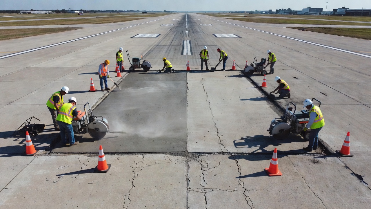
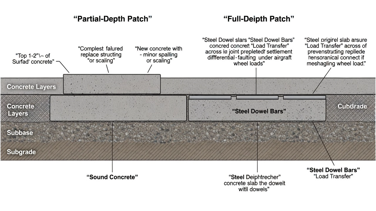
Concrete patching is a pavement maintenance and repair technique that involves removing localized areas of deteriorated or distressed Portland cement concrete (PCC) and replacing them with fresh repair material to restore the pavement’s structural integrity, surface profile, and ride quality. The term encompasses two distinct categories: partial-depth patching, which addresses defects confined to the upper portion of the slab (typically 1 to 2 inches deep), and full-depth patching, which removes the entire slab thickness to address structural failures extending to the full depth of the PCC layer.
In the context of airport pavements, concrete patching is a critical maintenance operation governed by FAA Advisory Circular 150/5380-6C, Guidelines and Procedures for Maintenance of Airport Pavements, and referenced in ICAO Doc 9157, Aerodrome Design Manual — Part 3: Pavements. The primary objective of patching is to arrest the progression of distress, eliminate foreign object debris (FOD) hazards, restore load transfer at joints and cracks, and prevent water infiltration into the pavement foundation. Patches that fail prematurely — particularly through delamination or debonding from the parent concrete — represent a significant operational concern, as they generate loose debris that can be ingested by jet engines or cause damage to aircraft tires and landing gear.
The Florida Department of Transportation Airfield Pavement Distress Repair Manual categorizes PCC patching into two main repair types: PCC Partial-Depth Patching for distresses confined to the top few inches of the slab, and PCC Full-Depth Patching for structural and material-related distresses extending through the slab. The manual further distinguishes between permanent/semi-permanent repairs that address the cause of failure and mitigate distress effects, and temporary/emergency repairs that address immediate safety concerns without fully correcting the underlying deficiency. The decision between partial-depth and full-depth repair hinges on the type, extent, severity, and location of distress, as determined through systematic pavement condition inspection per ASTM D5340, Standard Test Method for Airport Pavement Condition Index Surveys.
2. Patch Types: Partial-Depth vs. Full-Depth
2.1 Partial-Depth Patching
Partial-depth patching is the removal and replacement of shallow, localized areas of deteriorated concrete, typically to a depth of 1 to 2 inches (25 to 50 mm) below the pavement surface. This method is used exclusively for distresses that are confined to the upper portion of the slab and do not compromise the structural capacity of the full slab section. According to the FHWA Generic Guide Specification for Partial-Depth Repairs, areas less than 6 inches (150 mm) in length and 1.5 inches (35 mm) in width at the widest point are not repaired under partial-depth patching specifications but are instead filled with joint sealant material.
Distresses suitable for partial-depth patching include:
Distress Type
Description
Typical Cause
Joint Spalling
Breakdown of concrete at joints, typically within 2 feet of the joint
Infiltration of incompressibles, poor joint sealant, traffic loading
Corner Spalling
Spalling at slab corners, typically diagonal from the corner
Same as joint spalling, often combined with corner loading
Scaling
Localized flaking or peeling of the surface mortar
Small conical depressions where aggregate particles have fractured and dislodged
Reactive aggregates, freeze-thaw of porous particles
Shallow Delaminations
Horizontal separation just below the surface detected by sounding
Construction deficiencies, lack of curing, ASR
The FDOT Airfield Pavement Distress Repair Manual specifies that partial-depth patching can serve as a permanent repair for corner spalling, joint spalling, and small patches, and as a temporary repair for corner breaks, durability “D” cracking, large patching, utility cut patching, longitudinal/transverse/diagonal cracking, and scaling. This classification underscores that partial-depth repair is not a structural fix — it restores surface integrity and eliminates FOD hazards but does not address underlying base or subgrade deficiencies.
Key dimensional requirements per FAA and FHWA guidance include: a minimum saw cut depth of 1 inch (25 mm) with the excavation extending at least 1/2 inch (13 mm) into visually sound concrete below the deteriorated material; a minimum lateral extension of 3 inches (75 mm) beyond the visible distress limits; and a rectangular repair geometry with vertical saw-cut faces at the perimeter to ensure proper bonding and prevent future edge spalling.
2.2 Full-Depth Patching
Full-depth patching involves the complete removal and replacement of the entire PCC slab thickness within a limited portion of a pavement slab. This structural repair method is employed when deterioration extends through the full depth of the concrete pavement, compromising load transfer, slab continuity, and the structural integrity of the pavement section. The FAA AC 150/5380-6C defines three subcategories of full-depth repair: corner break repair, partial slab replacement, and full slab replacement, each with specific saw-cut patterns and load-transfer restoration requirements.
Distresses requiring full-depth patching include:
Corner Break: A crack that intersects the slab corner with the joint, caused by combined loading and inadequate subgrade support
Shattered Slab / Intersecting Cracks: Multiple cracks dividing the slab into four or more pieces, indicating structural fatigue
Blowup: Buckling or shattering due to thermal expansion in joints filled with incompressibles
Large Patching and Utility Cut Patching: Previously patched areas that have failed and require structural rehabilitation
For full-depth patches, the FDOT Airfield Pavement Distress Repair Manual requires making full-depth vertical saw cuts at least 2 feet (0.6 m) beyond the limits of the repair area, with cuts oriented perpendicular to constructed joints. All unsound concrete is removed, subgrade or base material is restored if required, and deformed tie bars are installed into the face of the parent panel while dowel bars are installed into the face of adjacent panels to restore load transfer. The repair area is then filled with concrete, consolidated with a vibrator, finished to match the existing surface, cured, and fitted with new joint sealant.
3. Materials for Concrete Patching
The selection of patching materials is governed by the required opening time (time to traffic), ambient temperature at placement, depth of repair, compatibility with existing substrate, and the structural demands of the repair location. The FHWA Generic Guide Specification and FAA AC 150/5380-6C recognize several material categories, each with distinct performance characteristics.
Accelerated strength PCC is the most widely specified patching material for highway and airfield applications. The FHWA specification requires that this mixture achieve a minimum compressive strength of 3,000 psi (20.7 MPa) in 24 hours using Type I or Type III Portland cement, with calcium chloride or other approved accelerator. The plastic concrete must have an air content of 6.5 percent ± 1.5 percent and a slump of 1 to 3 inches (25 to 75 mm) at the time of placement.
The primary advantage of accelerated PCC is its compatibility with the existing pavement — the thermal expansion coefficient, modulus of elasticity, and long-term strength gain characteristics are similar to the parent concrete, reducing the risk of thermal incompatibility failure. However, the required 24-hour curing period before opening to traffic makes this material unsuitable for emergency runway repairs where faster turnaround is required.
3.2 Rapid-Setting Repair Materials
Rapid-setting repair materials are formulated to achieve a minimum compressive strength of 3,000 psi (20.7 MPa) within 24 hours, with many proprietary systems reaching traffic-ready strength in 2 to 6 hours. The FHWA specification requires that these materials be installed strictly in accordance with the manufacturer’s written instructions, including surface preparation, bonding procedure, and curing regimen. The FAA recommends that rapid-setting materials be selected from an approved list and verified through laboratory testing before field deployment.
Common rapid-setting systems include:
Calcium Aluminate Cement (CAC)-based mortars: Achieve rapid strength gain through controlled hydration of calcium aluminate phases. CAC-based materials offer good resistance to sulfate attack and can be formulated for placement at low temperatures, but require careful control of the water-cement ratio to avoid conversion reactions that reduce long-term strength.
Magnesium Phosphate Cement (MPC): Research by Seehra, Gupta, and Kumar (1993) demonstrated that MPC develops 100–200 kg/cm² (1,420–2,840 psi) compressive strength within one hour of application, with 4-hour strength exceeding the 7-day strength of ordinary Portland cement concrete. MPC uses a borax additive to control setting time, though this reduces early strength. The material is particularly suitable for cold-weather patching and enables traffic reopening within 4 to 5 hours of placement.
Polymer-Modified Cementitious Mortars: Incorporate polymer latex additives (styrene-butadiene, acrylic, or polyvinyl acetate) to improve bond strength, reduce permeability, and enhance freeze-thaw durability. These materials offer a balance of rapid strength gain and material compatibility.
3.3 Cementitious Mixtures with Supplementary Materials
Silica fume concrete incorporates ultra-fine silica fume (a byproduct of silicon alloy production) at dosages of 5–15 percent by weight of cement. Silica fume reacts with calcium hydroxide from cement hydration to form additional calcium-silicate-hydrate (C-S-H), densifying the paste matrix and dramatically reducing permeability. Silica fume concrete achieves very high bond strengths (typically exceeding 500 psi in pull-off testing) and provides exceptional resistance to chemical attack and abrasion. Research published in Cement and Concrete Research demonstrates that silica fume-modified concrete can achieve 24-hour compressive strengths exceeding 5,000 psi (34.5 MPa) when used with high-range water reducers and proper curing. However, silica fume concrete requires moist curing for a minimum of 7 days and is susceptible to plastic shrinkage cracking if not cured immediately after finishing, limiting its use in rapid-repair applications.
Polymer-modified concrete incorporates polymer latex emulsions that form a continuous polymer film throughout the cement paste matrix upon curing, improving tensile strength, bond strength (typically 40–60 percent higher than unmodified concrete), and resistance to freeze-thaw damage. Latex-modified concrete is commonly specified for bridge deck overlays and thin-bonded patching applications where high bond integrity is critical.
3.4 Epoxy Resin Mortars and Epoxy Concrete
Epoxy resin repair mortars consist of epoxy resin and catalyst blended with carefully graded fine aggregates to produce a high-strength, rapid-curing patching material. Per the FHWA Generic Guide Specification, epoxy systems require preconditioning of components to achieve a blended liquid temperature between 75°F (24°C) and 90°F (32°C) before aggregates are added. The mixture must be proportioned and blended in strict compliance with manufacturer recommendations, used within one hour of mixing, and discarded if it begins to generate appreciable heat (indicating the onset of exothermic polymerization).
Epoxy concrete — a mixture of epoxy binder with both fine and coarse aggregates — offers compressive strengths exceeding 8,000 psi (55 MPa) within 3 hours and exceptional bond strength to properly prepared concrete substrates. The entire surface of the repair area must be primed with neat blended epoxy immediately before placement, with the primer extending onto the surface adjacent to the repair. The repair must remain undisturbed for at least 3 hours before traffic loading.
The limitations of epoxy systems include: sensitivity to moisture during application (epoxy will not bond to wet or damp surfaces); high thermal expansion coefficient (approximately 2–3 times that of PCC), creating potential for debonding under thermal cycling; and cost, which is 5–10 times higher than cementitious materials.
3.5 Methyl Methacrylate (MMA) Polymer Concrete
MMA polymer concrete, such as the Transpo T-17 system widely used in United States airports, represents a specialized category of rapid-patching materials designed for emergency and overnight airfield repairs. T-17 is a prepackaged, two-component, 100 percent reactive methyl methacrylate system that achieves full cure in 45 minutes at 70°F (21°C) and can be opened to traffic in less than 90 minutes. Key performance characteristics published by the manufacturer include compressive strength exceeding 5,000 psi (34.5 MPa) at 3 hours and surpassing 9,000 psi (62 MPa) at 24 hours, with a wide application temperature range of 14°F to 100°F (-10°C to 38°C).
MMA polymer concrete offers distinct advantages for airfield patching: it forms a strong chemical bond to the existing PCC substrate without requiring mechanical interlock; it is freeze-thaw resistant; and it can be placed as a neat mortar for thin patches (1/4 inch) or as an aggregate-filled mortar for partial or full-depth repairs in a single pour. The system requires only standard concrete mixing equipment and minimal labor. A thin coat of primer is used to seal the existing concrete surface and increase bond strength before the MMA material is placed.
4. Surface Preparation
Surface preparation is widely recognized as the single most critical factor determining patch longevity. Inadequate preparation is the root cause of the majority of patch-bond failures. The FHWA Partial-Depth Repair Specification and FAA AC 150/5380-6C prescribe a sequential preparation process that must be followed rigorously.
4.1 Saw-Cutting
A saw cut must be made around the entire perimeter of the repair area to provide a vertical face at the edges and a clean termination of the patch boundary. The saw cut shall have a depth of 1 to 2 inches (25 to 50 mm) for partial-depth repairs. For full-depth repairs, the saw cut extends through the full slab thickness. The saw cut should extend a minimum of 3 inches (75 mm) beyond the visible distress limits for partial-depth patches and a minimum of 2 feet (0.6 m) beyond for full-depth patches, ensuring that the repair encompasses all deteriorated material.
The saw cut serves multiple functions: it creates a clean vertical face that eliminates feathered edges prone to spalling; it prevents damage to sound concrete outside the repair area during chipping operations; and it provides a reservoir for joint sealant when the patch abuts an existing joint or crack. The FDOT manual specifies that saw cuts must be made perpendicular to constructed joints and that the repair area should be rectangular in plan view.
4.2 Concrete Removal (Chipping)
Concrete within the repair area is broken out using pneumatic hammers weighing 30 pounds (13.6 kg) or less. The FAA AC 150/5380-6C specifically limits chipping hammer weight to 30 pounds or less to prevent microcracking of the sound concrete substrate that would compromise patch bond. Heavy breakers generate impact forces that create microfractures extending 1/2 inch or more into the remaining concrete, creating planes of weakness where the patch will subsequently debond.
All unsound, broken, or deteriorated concrete must be removed down to sound material, with a minimum removal depth of at least 1/2 inch (13 mm) into visually sound concrete. The exposed concrete faces should be rough and textured to provide mechanical interlock for the repair material. For full-depth repairs, the base and subgrade are inspected after concrete removal, and any deteriorated base material is removed and replaced with new compacted base.
4.3 Surface Cleaning
After concrete removal, the exposed faces must be thoroughly cleaned to remove all loose particles, oil, dust, asphalt concrete traces, curing compound residue, and other contaminants that could inhibit bond. The FHWA specification requires sandblasting of all exposed concrete faces, followed by removal of all sandblasting residue immediately before placement of the bonding agent.
Alternative cleaning methods include: high-pressure water blasting (3,000–10,000 psi) which is effective at removing laitance and exposing sound aggregate without damaging the substrate; and compressed air blowing with oil-free air to remove dust and debris. The repair cavity must be completely dry before placement of epoxy or polymer materials, and may be either dry or saturated surface-dry (SSD) for cementitious materials, depending on the manufacturer’s recommendation.
4.4 Bonding Agent Application
A bonding agent is applied to the prepared concrete surfaces to ensure adhesion between the existing substrate and the new repair material. The type of bonding agent depends on the repair material system:
Repair Material
Required Bonding Agent
Application Method
Accelerated PCC
Epoxy bonding agent (Class I or III per AASHTO M-235)
Thin coat scrubbed into surface with stiff bristled brush
Normal PCC
Sand-cement grout (1:1 cement to sand by volume with water to creamy consistency)
Scrubbed evenly over surface; repair placed before grout dries
Epoxy Mortar/Concrete
Neat blended epoxy primer
Applied immediately before placement, overlapping onto adjacent surface
MMA Polymer Concrete
Manufacturer-supplied primer
Thin coat applied to seal substrate
Rapid-Setting Materials
As recommended by manufacturer
Per manufacturer’s written instructions
For accelerated PCC repairs that will be opened to traffic within 4 to 6 hours, the FHWA specification requires an epoxy bonding agent. The epoxy prime coat is applied in a thin coating and scrubbed into the surface with a stiff bristled brush. Placement of the concrete should be delayed until the epoxy becomes tacky — typically 15 to 30 minutes at 70°F depending on the epoxy formulation.
5. Placement and Curing
5.1 Placement Procedures
The repair mixture must be placed and consolidated to eliminate essentially all voids at the interface between the repair and the existing concrete. Consolidation is achieved through internal vibration using 1-inch diameter pencil vibrators inserted at 6- to 12-inch intervals, or through external vibration of forms for precast repairs. The material must be worked thoroughly into corners and along vertical faces to ensure complete filling of the cavity and intimate contact with the bonding agent.
If a partial-depth repair area abuts a working joint or crack that penetrates the full depth of the pavement, a compressible insert medium (such as closed-cell polyethylene foam backer rod or preformed joint filler) must be used to maintain the working joint and prevent compression- or restraint-induced cracking of the repair. Contact between the repair and any adjacent pavement that could cause compression or other types of failure must be prevented.
5.2 Finishing
All repairs must be finished to the cross-section of the existing pavement. The repair surface is screeded using a straightedge to match the existing pavement grade and cross-slope, then textured to conform to the existing pavement texture. For airport pavements, burlap drag, tining, or grooving may be used to produce the required surface friction characteristics consistent with FAA AC 150/5320-6 requirements for pavement surface texture.
The FDOT Airfield Pavement Distress Repair Manual emphasizes that finishing should replicate the surrounding pavement texture to prevent differential friction characteristics that could affect aircraft braking performance or hydroplaning potential.
5.3 Curing
Curing is essential for proper strength development and bond integrity. The FHWA specification requires that curing compound be applied immediately after texturing at the rate of 150 square feet per gallon (3.7 m² per liter) per AASHTO M-148. For Portland cement concrete repairs, the following temperature restrictions apply:
Repairs shall not be placed when the air or pavement temperature is below 40°F (4°C)
At air temperatures below 55°F (13°C), a longer cure period may be required
Insulation may be used to improve the rate of curing in cool weather
For polymer and epoxy materials, the manufacturer’s curing recommendations take precedence over generic PCC curing requirements. MMA polymer concrete (such as T-17) requires no external curing since the polymerization reaction is self-contained and moisture-independent, representing a significant advantage for airfield repairs where rapid reopening is required.
6. Patch-Bond Failure
Patch-bond failure — the loss of adhesion between the patch material and the existing concrete substrate — is the most common and consequential recurring defect in concrete patching. According to the ACRP (Airport Cooperative Research Program) research on rapid slab repair and replacement of airfield concrete pavement, debonding at the patch interface is the primary mode of failure for partial-depth repairs, affecting an estimated 15–30 percent of patches within 2 to 5 years of installation depending on material selection and preparation quality.
6.1 Mechanisms of Patch-Bond Failure
Adhesive Failure occurs at the interface between the bonding agent and either the substrate or the repair material. Causes include: inadequate surface preparation leaving laitance, dust, or contaminants on the substrate; application of bonding agent to a saturated or frozen surface; placement of repair material after the bonding agent has dried or cured beyond its open time; and moisture-sensitive epoxy formulations applied to damp concrete.
Cohesive Failure occurs within the repair material or within the substrate near the bond line. This failure mode indicates that the bond strength exceeded the tensile strength of one of the materials. It can result from: thermal incompatibility (the patch expands and contracts at a different rate than the parent concrete, generating shear stresses at the interface); differential shrinkage between the low-shrinkage substrate and the often higher-shrinkage repair material; and freeze-thaw damage in the substrate immediately adjacent to the patch boundary.
Edge Spalling occurs at the perimeter of the patch where the saw-cut face meets the parent concrete. This failure results from the stress concentration at the vertical corner, combined with the differential movement between the two materials under thermal and moisture cycles.
6.2 Factors Contributing to Patch-Bond Failure
Factor
Effect
Mitigation
Improper saw-cut depth
Feathered edges at patch boundary spall under traffic
Cut minimum 1 inch depth; extend 3 inches beyond distress
Heavy chipping hammers >30 lb
Microcracking of substrate up to 0.5 inch deep
Use lightweight hammers; chip to sound concrete
Inadequate cleaning
Dust film prevents bond (reduces bond by 50–80%)
Sandblast or high-pressure water clean
Bonding agent errors
Missed open time, wrong material, insufficient coverage
Follow manufacturer’s instructions exactly
Thermal incompatibility
Differential movement causes shear at bond line
Select material with CTE close to PCC
Moisture during cure
Steam voids at bond interface for epoxy systems
Ensure dry surface for epoxy; SSD for cementitious
7. Inspection of Concrete Patches
7.1 Inspection Methods
Concrete patch condition is evaluated using both visual inspection and sounding techniques as prescribed by ASTM D5340, Standard Test Method for Airport Pavement Condition Index Surveys. The PCI survey quantifies patch distress by severity and extent on a scale of 0 (failed) to 100 (excellent). Patches are evaluated for:
Patch-bond failure (debonding): Detected through hollow sound when tapping with a hammer, chain drag, or rod; may be accompanied by edge cracking
Patch cracking: Cracks propagating within the patch material itself, rated by width (low: <1/8 inch; medium: 1/8–1/2 inch; high: >1/2 inch)
Patch spalling: Flaking or disintegration at patch edges, rated by spall depth and affected area
Patch surface deterioration: Revealing of aggregate, scaling, or popouts within the patch
Sounding is performed using a 2-pound engineer’s hammer for small areas or a 50-pound chain drag for large pavement areas. A hollow or drum-like sound indicates delamination between the patch and the substrate. The repair area boundaries are precisely mapped when delamination is detected.
7.2 Bond Strength Testing
For quantitative assessment of patch bond integrity, pull-off testing per ASTM C1583/C1583M, Test Method for Tensile Strength of Concrete Surfaces and the Bond Strength or Tensile Strength of Concrete Repair and Overlay Materials, is the standard method. A 2-inch (50 mm) diameter steel disc is epoxied to the prepared patch surface, and a tensile load is applied perpendicular to the surface using a portable pull-off tester. The tensile stress at failure and the mode of failure (adhesive at patch-substrate interface, cohesive within patch, cohesive within substrate, or adhesive at bonding agent interface) are recorded.
The FHWA Mobile Concrete Testing Center recommends a minimum acceptable bond strength of 200 psi (1.4 MPa) for partial-depth repairs, though many agencies specify 250–300 psi for airfield pavements subjected to high-speed aircraft traffic.
7.3 Post-Installation Inspection Timeline
Inspection Interval
Purpose
24–48 hours after placement
Verify cure, check for early cracking or debonding
30 days after placement
Assess initial bond integrity and edge condition
6 months after placement
Evaluate under first seasonal temperature cycle
12 months after placement
Full condition survey; identify latent failures
Annually thereafter
Per FAA PMP requirements for AIP-obligated airports
8. Patching in Airport PCC Pavements
Airport pavement patching is governed by requirements that differ significantly from highway patching due to the operational demands of aircraft traffic. FAA AC 150/5380-6C provides specific guidance for airport pavement repair methods, emphasizing that patching must address the following airfield-specific concerns:
Foreign Object Debris (FOD) Prevention: Loose concrete fragments, dislodged aggregate particles, and spalled patch edges are FOD hazards that can be ingested by jet engines, causing catastrophic engine failure. The FAA mandates that all patches be finished flush with the surrounding pavement and that any loose material be vacuumed or swept before reopening the pavement to aircraft traffic.
Operational Safety During Construction: The FAA requires a Construction Safety and Phasing Plan (CSPP) per AC 150/5370-2 for maintenance activities on active airfields. The CSPP must address: identification of affected pavement areas; impact on normal aircraft operations; temporary changes to air traffic procedures, aircraft rescue and fire fighting (ARFF) capabilities, or other operations; and risk management measures including barricades, signage, lighting, and personnel protection.
Rapid Turnaround: Airport closures for pavement repair are extremely costly. The FAA’s Airport Improvement Program (AIP) requires airports to minimize runway closure durations. This drives the selection of rapid-setting materials that allow reopening within 90 minutes to 4 hours of placement. MMA polymer concrete and magnesium phosphate cement are the primary materials used for emergency and overnight airfield patching.
Load Transfer Restoration: For full-depth patches adjacent to joints in airfield pavements, load transfer must be restored through the installation of dowel bars — smooth steel bars (typically 1.25 to 1.5 inches in diameter and 18 inches long) placed at mid-depth of the slab at 12-inch spacing across the joint. The FDOT manual specifies that deformed tie bars be installed into the face of the parent panel to prevent separation, while dowel bars into adjacent panels provide load transfer without restricting joint opening.
8.1 FAA Specification for Airport Patch Materials
The FAA AC 150/5370-10, Standards for Specifying Construction of Airports, contains the detailed material specifications (P-501 for PCC pavements) that govern patching materials for federally funded airport projects. Key requirements include:
Air content: 5.0% to 8.0% for freeze-thaw durability
Slump: 1 to 3 inches (25 to 75 mm)
Flexural strength: Minimum 650 psi (4.5 MPa) at 28 days
8.2 Rapid-Setting Materials for Airfield Repair
The U.S. Army Corps of Engineers Engineer Research and Development Center (ERDC) conducted field demonstrations of magnesium phosphate concrete (MPC) for airfield pavement repairs, specifically evaluating resilience to heat and petroleum, oils, and lubricants (POL) exposure — conditions commonly encountered on airfield aprons and taxiways. The study found that MPC patches retained structural integrity after exposure to jet fuel, hydraulic fluid, and deicing chemicals, demonstrating suitability for operational airfield environments where chemical spills are routine.
The Transpo T-17 MMA polymer concrete system has been deployed at numerous U.S. airports including Detroit Metropolitan Wayne County Airport (DTW) for runway and taxiway repairs. The system’s ability to achieve full service strength within 45 minutes at 70°F with a wide application temperature range of 14°F to 100°F makes it suitable for year-round airfield maintenance operations.
9. Patch Durability and Performance
9.1 Service Life Expectations
The expected service life of concrete patches varies significantly based on material selection, surface preparation quality, and traffic conditions. Based on data from the FHWA Long-Term Pavement Performance (LTPP) program and ACRP research:
Patch Type
Material
Expected Service Life
Partial-depth
Accelerated PCC
3–7 years
Partial-depth
Epoxy mortar
5–10 years
Partial-depth
MMA polymer concrete
8–12 years
Full-depth
PCC with dowels
10–20 years
Full-depth
Polymer concrete
8–15 years
9.2 Factors Affecting Durability
Thermal compatibility between the patch material and the parent concrete is the most important material property affecting long-term durability. The coefficient of thermal expansion (CTE) of typical PCC is approximately 5.5 × 10⁻⁶ /°F (10 × 10⁻⁶ /°C) , while epoxy mortars have CTEs of 15–30 × 10⁻⁶ /°F, creating differential strains of 0.02–0.04 percent per 30°F temperature change. Over multiple cycles, these differential strains generate shear stresses at the bond interface that can exceed the bond strength.
Drying shrinkage of cementitious repair materials is a second major concern. While the existing concrete has undergone most of its drying shrinkage over years of service, the new patch material undergoes full drying shrinkage in the weeks following placement. This differential shrinkage generates tensile stresses at the bond interface, potentially causing edge lifting and debonding. The use of shrinkage-compensating cements, low-shrinkage polymer-modified mortars, or expansive admixtures can mitigate this effect.
10. Partial-Depth vs. Full-Depth Decision Matrix
The selection between partial-depth and full-depth repair requires systematic evaluation of distress characteristics. The following decision criteria should be applied during pavement inspection:
Condition
Partial-Depth
Full-Depth
Distress depth
Confined to top 1–2 inches
Extends through full slab
Spalling at joints/corners
Yes, if sound concrete below
Yes, if structural damage exists
Corner break
No (use full-depth for corner breaks)
Yes
Shattered slab
No
Yes
LTD cracking
Only if <1/8 inch width, shallow
If full-depth or wide cracks
Pumping evident
No
Yes
Sounding results
Solid below 2 inches
Hollow throughout depth
Load transfer required
No
Yes — install dowel bars
Base/subgrade condition
Presumed sound
Must inspect and repair if needed
Time to traffic
4–24 hours depending on material
24–72 hours depending on material
The FAA AC 150/5380-6C Quick Guide for Maintenance and Repair of Common Rigid Pavement Surface Problems (Table 6-2) provides a summarized decision framework linking specific distress types to recommended repair methods, including partial-depth patching, full-depth patching, crack sealing, joint sealing, grinding, slab replacement, and reconstruction.
Related Terms
Concrete
— Portland cement concrete as a construction material
Crack
— Crack types and fracture mechanics in materials
Maintenance
— Preventive and remedial pavement maintenance
Frequently Asked Questions
Partial-depth patching removes only the top 1–2 inches (25–50 mm) of deteriorated concrete to repair surface defects like spalls, scaling, and popouts that are confined to the slab surface. Full-depth patching removes the entire thickness of the PCC slab to repair structural distresses such as corner breaks, shattered slabs, and severe cracking, often requiring dowel bars for load transfer. The choice depends on the depth of deterioration and whether the distress is structural or cosmetic.
Common patching materials include accelerated Portland cement concrete (achieving 3,000 psi in 24 hours), rapid-setting repair materials (3,000 psi within 24 hours), epoxy resin mortars and epoxy concrete, polymer-modified concrete such as methyl methacrylate (MMA) polymer concrete, magnesium phosphate cement (MPC) which develops strength within one hour, and silica fume concrete for high durability. The FAA AC 150/5380-6C and FHWA guidelines specify material requirements for airport pavement repairs.
Patch-bond failure is the most common recurring defect in concrete patching. It occurs when the repair material loses adhesion to the existing substrate, resulting in debonding, cracking along the patch perimeter, and spalling at the edges. Primary causes include inadequate surface preparation (insufficient saw-cutting, improper chipping, or lack of sandblasting), failure to apply a proper bonding agent, curing deficiencies, thermal incompatibility between patch material and parent concrete, and incorrect material selection for the application conditions.
Airport concrete patching follows FAA AC 150/5380-6C guidelines. The procedure begins by marking the repair limits and making vertical saw cuts 1–2 inches deep for partial-depth patches or full-depth for structural repairs. All unsound concrete is removed using pneumatic hammers weighing 30 pounds or less. The cavity is sandblasted to remove debris and contaminants, then a bonding agent is applied. The repair material is placed, consolidated, finished to match adjacent pavement texture, and cured. Rapid-setting materials may allow reopening to traffic within 90 minutes to 4 hours, depending on the material.
Concrete patches are inspected visually and through sounding (chain drag or hammer tap) to detect debonding and delaminations. ASTM D5340 defines the standard method for airport pavement condition index (PCI) surveys that quantify patch condition. Pull-off testing per ASTM C1583 measures tensile bond strength between patch and substrate. Inspectors also examine for edge spalling, cracking at patch boundaries, surface deterioration, and joint sealant condition. Common patch distresses include patch-bond failure (debonding), patch cracking, and patch spalling.
Full-depth patching is required when deterioration extends through the full slab thickness, including corner breaks, shattered slabs, severe intersecting cracks, and structural failures from overloading. Partial-depth patching is appropriate only for surface-confined distresses such as joint spalling, corner spalling, scaling, popouts, and shallow delaminations where sound concrete exists below the distressed layer. If sounding reveals hollow areas extending deeper than 2 inches, full-depth repair is typically indicated.
Extend the Life of Your Airport Pavements
Proper concrete patching techniques and material selection are critical for maintaining safe, durable airport pavements. Our experts provide guidance on inspection, repair strategies, and quality assurance for PCC patching projects. Contact us to discuss your pavement maintenance needs.
Patch condition is a standard inspection item in airport and highway pavement condition surveys. Well-performing patches indicate good maintenance practices; fa...
Concrete scaling is the deterioration of the upper pavement surface in Portland Cement Concrete (PCC) slabs, typically 3-13 mm deep, caused by freeze-thaw cycle...
17 min read
Concrete
Pavement
+4
Cookie Consent We use cookies to enhance your browsing experience and analyze our traffic. See our privacy policy.