A construction joint is an intentional interface between successive concrete placements, created when a concrete pour is stopped and later resumed. Proper joint preparation including cleaning, roughening, and bonding agent application is essential for structural continuity. Cold joints — where no bond exists — are a concrete defect. Covers construction joint types, preparation methods, cold joint detection, inspection, waterproofing, and repair.
Definition and Purpose
A construction joint is a deliberate, planned interface between two successive placements of concrete. Per ACI CT-16 (Concrete Terminology), it is defined as “the surface where two successive placements of concrete meet; typically planned and located to facilitate construction, or occurring as a result of inadvertent delays in concrete placing operations.” The ACI 224.3R-95 (Joints in Concrete Construction) — the primary ACI state-of-the-art report on joint design, construction, and maintenance — further defines construction joints as “joints placed to define the extent of individual placements, generally in conformity with a predetermined joint plan. They permit in-plane slip unless tied by design.”
The fundamental purpose of a construction joint is to allow concrete construction to proceed in discrete, manageable placements while maintaining structural continuity between the pours. No concrete structure of significant size can be placed monolithically — practical limitations of concrete delivery rates, formwork capacity, crew size, and placing equipment all necessitate planned interruptions. A properly designed and executed construction joint transfers shear, axial, and flexural forces across the interface through a combination of three mechanisms: aggregate interlock from the intentionally roughened surface, shear-friction from reinforcement crossing the joint plane, and chemical bonding between the new and old concrete.
Construction joints must be clearly distinguished from other joint types. Contraction joints (also called control joints) are weakened planes created by saw-cutting or forming to control cracking from drying shrinkage and thermal contraction — they are designed to crack. Expansion joints (isolation joints) provide complete separation between adjacent structural elements to allow independent movement in response to thermal expansion, creep, and shrinkage. Construction joints lie between these — they are structural interfaces that must maintain continuity of force transfer across the plane. Per ACI 224.3R-95, the key distinctions are that construction joints allow relative slip in-plane unless tied with reinforcement, while contraction joints intentionally crack and expansion joints provide complete separation.
The critical design provision for construction joints is found in ACI 318-19 Section 26.5.6. The code mandates that construction joints must be located to minimize their effect on the strength of the structure, that joints shall be designed per shear-friction provisions of Section 22.9 when shear is to be transferred, that the surface of hardened concrete must be cleaned of laitance, dirt, and contaminants, and that where shear-friction is required, the surface must be intentionally roughened to a full amplitude of approximately 1/4 inch (6 mm). The consequences of inadequate surface preparation are quantified in ACI 318, Table 22.9.4.2, which lists shear-friction coefficient values. For concrete placed against hardened concrete with intentional roughening, the coefficient is μ = 1.0λ. For concrete placed against hardened concrete without roughening, the coefficient drops to μ = 0.6λ — a 40% reduction in design shear capacity.
Planned vs Emergency Construction Joints
Construction joints fall into two categories based on the circumstances of their creation.
Planned construction joints are shown on contract drawings and are incorporated into the structural design. Their locations are selected to satisfy structural requirements while facilitating construction operations. Per ACI 318-19 Section 26.5.6.1(a), joints in beams are typically offset a distance equal to twice the width of the intersecting member from the face of beams or columns. In slabs, joints are located near quarter-span points where bending moments are lowest. In columns, joints are placed at least 2 inches (50 mm) below the lowest soffit of beams or girders framing into the column. Reinforcement continuity across the joint is designed and detailed in the structural drawings, and surface preparation is specified as a contract requirement. The shear-friction mechanism per ACI 318-19 Section 22.9 is explicitly checked in design, with the required reinforcement calculated as Avf = Vu / (φ fy μ).
Emergency (unplanned) construction joints are created when an unexpected interruption forces a stop in concrete placement. Common causes include concrete delivery delays exceeding 30 minutes, pump or conveyor breakdown, vibrator failure, sudden weather changes including heavy rain, formwork failure or leakage, or the concrete reaching initial set before the pour is complete. When a delay forces an emergency joint, the engineer or inspector must immediately assess whether the interruption location is acceptable. Per ACI 302.1R (Guide for Concrete Floor and Slab Construction), the contractor must form a bulkhead at the location where concrete is still workable. The resulting joint must then be treated with the same surface preparation as a planned joint — laitance removal by sandblasting or hydrodemolition and roughing to the 1/4 inch amplitude requirement. The structural engineer must verify that the emergency joint location is adequate for the forces at that section and may require additional reinforcement or dowels across the joint.
The critical distinction between a planned and emergency joint versus a cold joint is whether the concrete had reached initial set before the subsequent placement. If the surface is still plastic and can be remixed with fresh concrete (within approximately 30-45 minutes in normal weather), no joint exists at all — the concrete remains monolithic. If the surface has passed initial set (typically 2-4 hours after mixing), and the surface is properly prepared, an acceptable construction joint is created. If the surface has passed initial set and no preparation is performed, the result is a cold joint — a defect.
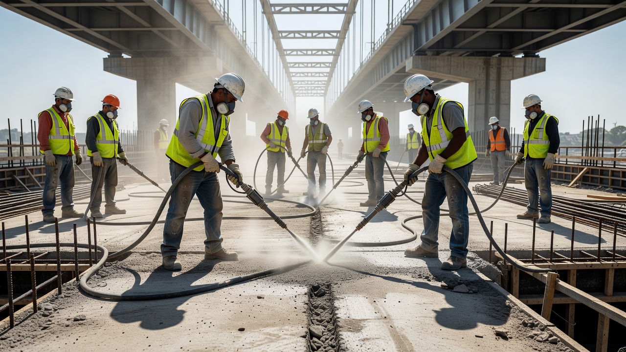
Joint Preparation Methods
Per ACI 318-19 Section 26.5.6.2(d): “Construction joints shall be cleaned and laitance removed before new concrete is placed.”Laitance is defined by ACI CT-16 as “a layer of weak material derived from cementitious material and aggregate fines, carried by bleeding to the surface, or separated from the mixture during placement.” This layer, typically 1-3 mm thick, has negligible tensile or shear strength and must be completely removed to achieve structural bond between pours.
Green Cutting (Wet Brushing)
Green cutting is applied 2 to 6 hours after concrete placement, while the concrete is still in its early hardening stage but stiff enough to resist aggregate dislodgement. The method uses wire brushing or light water blasting after bleed water has evaporated. The timing window is critical — too early dislodges aggregate and damages the surface, too late requires mechanical methods. Green cutting produces the best bond results of any method because it removes laitance while the aggregate is still well-anchored in the paste, exposing clean aggregate for mechanical interlock with the subsequent pour. It eliminates the need for secondary surface preparation and is the preferred method for horizontal construction joints in slab and wall construction.
Sandblasting
Sandblasting uses compressed air to propel abrasive media against the concrete surface. Typical application parameters include an air pressure of 90-100 psi at the nozzle, media such as silica sand (graded #8 to #30), slag, or garnet, and an application rate of 2-5 ft² per minute per nozzle for light cleaning. The resulting surface profile ranges from ICRI CSP (Concrete Surface Profile) 3 to 7, with light cleaning achieving CSP 3-5 and moderate cleaning achieving CSP 5-7. Depth of removal is typically 1/16 to 1/8 inch (1.5-3 mm). The USBR Best Practices Report (MERL 12-17) recommends wet sandblasting for horizontal construction joints to control airborne dust and improve surface finish. Dry sandblasting is effective but generates significant airborne crystalline silica and requires respiratory protection per OSHA standards.
Hydrodemolition (High-Pressure Water Jetting)
Hydrodemolition uses ultra-high-pressure water jets at 10,000 to 40,000 psi (70-275 MPa) with flow rates of 15-40 GPM to selectively remove deteriorated or weak concrete while leaving sound aggregate exposed. This method is recognized by ACI 546R (Concrete Repair Guide) as the preferred method for large-scale joint preparation. Depth control is excellent, removing 1/4 to 1 inch (6-25 mm) of surface material selectively. The resulting surface profile is CSP 5-9 per ICRI Guideline No. 03732. Effective production rates range from 5-30 square yards per hour depending on water pressure and concrete quality. Hydrodemolition produces the best bond surface of any mechanical method because it exposes clean, fractured aggregate without micro-cracking the substrate — unlike jackhammering or chipping which cause subsurface damage.
Bonding Agents
Bonding agents are applied to prepared joint surfaces immediately before the new concrete placement. Material options include epoxy bonding agents (ASTM C881 Type I/II, Grade 2/3), effective for thin overlays and structural repairs; cementitious grouts (1:1 or 1:2 cement-to-sand ratio), which must be applied within their drying time; acrylic/PVA bonding agents (polymer-modified), acceptable for non-structural applications; and neat cement paste, which has no bonding value once dried.
A critical finding from USBR MERL 12-17 (Best Practices for Preparing Concrete Surfaces Prior to Repairs and Overlays) is that bonding agents are not recommended for structural repairs and overlays where shear transfer is required. Mechanical interlock through surface roughening — not chemical bonding — is the primary mechanism for shear transfer across construction joints. The optimum ICRI CSP for structural joints is CSP 5-9. If the surface is too smooth (CSP 1-3), shear bond is reduced by up to 50%. If the surface is excessively rough (CSP 9+), air voids and honeycombing may form at the interface. The ASTM D5820 (sand patch) mean texture depth should be a minimum of 0.5 mm for non-structural joints and up to 3 mm for shear-critical joints.
Joint Type
Preferred Preparation Method
Alternative Method
Target ICRI CSP
Horizontal (slab-to-wall)
Green cutting
Sandblasting
CSP 3-5
Vertical (wall-to-wall)
Sandblasting or shotblasting
Hydrodemolition
CSP 5-7
Structural shear joint
Hydrodemolition
Heavy sandblasting
CSP 7-9
Non-structural joint
Wire brushing and wash
Light sandblasting
CSP 1-3
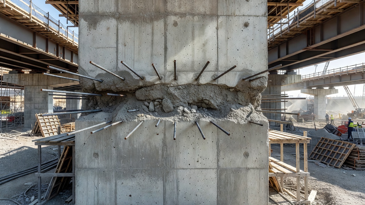
Cold Joint: Definition and Consequences
A cold joint is defined as “a plane of weakness in concrete caused by the placement of fresh concrete against concrete that has already begun to set (initial set has occurred), resulting in poor or absent intermingling between the two batches.” While a construction joint is planned, with surface preparation and design for shear transfer, a cold joint is unplanned — caused by delays, inadequate planning, or equipment failure, and typically lacking any surface preparation.
The critical time window for cold joint formation is governed by the concrete’s initial set time. In normal weather at 70°F (21°C), the maximum acceptable delay between successive concrete placements is 30 to 45 minutes. In hot weather at 90°F (32°C), the window narrows to 20 to 30 minutes. In cold weather at 40°F (4°C), the window extends to 45 to 60 minutes. For accelerated set concrete, the window may be as short as 10-20 minutes. For retarded mixes, it may extend to 60-90 minutes. The governing rule is: if the previously placed concrete has reached initial set (typically 2-4 hours after mixing depending on temperature, cement type, and water-cement ratio), a cold joint will form regardless of timing.
The structural consequences of cold joints are severe. Bond strength reduction ranges from 40 to 60% compared to properly prepared construction joints, as documented by research from USBR and ACI committees. Permeability increases up to 10 times normal values because the cold joint creates a continuous capillary pathway along the interface plane, providing a direct route for water, chlorides, and other aggressive agents into the concrete. Reinforcement corrosion is accelerated as chlorides and moisture migrate along the joint plane to reach embedded steel. In seismic events, cold joints create preferential failure planes where shear transfer is inadequate. Leakage is a common problem in water-retaining structures such as tanks, reservoirs, and below-grade walls where water finds the path of least resistance along the unbonded interface.
Consequence
Mechanism
Quantified Severity
Reduced bond strength
Lack of interlocking between batches
Shear capacity reduced by 40-60%
Increased permeability
Continuous capillary pathway
Up to 10x increase in water penetration
Reinforcement corrosion
Chloride/water ingress along joint
Service life reduced significantly
Structural weakness
Reduced shear transfer under lateral loads
Potential failure in seismic events
Leakage
Direct water paths through unsealed plane
Common in water-retaining structures
Inspection of Construction Joints
Inspection of construction joints is a critical component of concrete structure condition assessment. The inspection must determine whether the joint is performing as designed, whether a cold joint defect is present, and whether repair is required.
Chain Drag Sounding (ASTM D4580)
Chain drag sounding uses heavy chains (multiple lengths of 3/8 to 5/8 inch chain, 3-6 feet long) dragged across the concrete surface. A clear ringing sound indicates sound concrete with good bond at the joint plane. A dull thud or hollow sound indicates delamination or debonding at the joint interface. A rattling sound indicates shallow delamination. The FHWA Bridge Inspector’s Manual mandates chain drag inspection of bridge decks annually, with areas within 6 inches of construction joints receiving particular attention. Limitations per the WisDOT Structure Inspection Manual include ineffectiveness on asphalt-overlaid decks, inability to determine defect depth, interference from background noise above 70 dB, and the physical demands of manual operation.
Hammer Sounding
Hammer sounding uses a hammer (16-20 oz.) tapped at regular intervals, typically on a 6 inch (150 mm) grid for detailed inspection or random spacing for rapid screening. A sharp ring indicates sound monolithic concrete. A dull pop or hollow sound indicates delamination or debonding. A drummy sound indicates extensive separation at the joint plane. Per ASTM D4580, hammer sounding is the primary method for bridge deck delamination detection.
Pull-Off Bond Testing (ASTM C1583)
Pull-off testing provides quantitative bond strength measurement at construction joints. The method involves coring through the joint interface to a minimum depth reaching the substrate (typically 2 inches in diameter), bonding a steel disc to the surface with high-strength epoxy, and applying a hydraulic tensile load at approximately 5 psi/second until failure occurs. Acceptance criteria per ACI 562 require a minimum tensile bond strength of 200 psi (1.4 MPa) for structural repairs. Non-structural repairs require 150 psi (1.0 MPa). Bridge deck overlays typically require 250 psi (1.7 MPa), and airport pavement repairs per FAA P-501 require 300 psi (2.1 MPa).
The failure mode is recorded for each test: Mode A is adhesive failure at the overlay/substrate interface (bond failure), Mode B is cohesive failure in the substrate concrete, Mode C is cohesive failure in the overlay/repair material, and Mode D is adhesive failure at the epoxy/steel disc interface (invalid test). The desired failure type is Mode B, indicating that the bond strength exceeds the tensile strength of the substrate concrete.
Ultrasonic Pulse Velocity (ASTM C597)
Ultrasonic pulse velocity (UPV) testing measures the velocity of ultrasonic pulses passing through the concrete. When the pulse path crosses a construction joint, the velocity decreases if the joint zone has poor bond, voids, or delamination. Typical pulse velocity for sound concrete ranges from 3,500 to 4,500 m/s. A velocity drop of more than 15% across the joint indicates poor quality bond. Velocities below 3,000 m/s indicate voids or poor contact at the joint interface. UPV testing is effective for rapid screening of large surface areas and can map the extent of debonding zones.
Core Sampling (ASTM C42)
Core sampling provides direct observation of the joint interface. Cores are extracted through the joint and examined visually for voids, honeycombing, laitance layers, or lack of paste bonding. Laboratory testing can include splitting tensile strength across the joint plane and bond strength testing per ASTM C1583. Core observation also reveals the presence and condition of reinforcement crossing the joint.
Waterproofing at Construction Joints
Construction joints are the most vulnerable locations in concrete structures from a waterproofing perspective. Industry data indicates that more than 90% of water leaks in concrete structures occur at joints, with construction joints being the predominant source. Water ingress through construction joints leads to reinforcement corrosion, concrete deterioration, freeze-thaw damage in cold climates, and interior water damage in occupied structures.
PVC Waterstops
PVC waterstops are the traditional waterproofing solution for construction joints. They are made from flexible plasticized PVC meeting ASTM D4314, available in profiles including dumbbell, ribbed, center-bulb, and tear-web configurations. Widths range from 4 to 12 inches (100-300 mm) with thickness from 3/16 to 1/2 inch (5-12 mm). Hydrostatic rating reaches up to 200 feet (60 meters) of head depending on width and profile. Installation involves embedding the waterstop 50% into each side of the joint, with splices heat-welded in factory or field conditions. The principal limitation is that PVC waterstops are easily damaged during concrete placement, and damage is undetectable until leakage occurs. The general rule is that wider profiles with greater thickness provide higher hydrostatic resistance.
Hydrophilic (Swellable) Waterstops
Hydrophilic waterstops expand on contact with water to seal the joint. Bentonite-based types swell up to 16 times their dry volume on water contact, effective for heads up to 30-50 feet, but may deteriorate after cyclic wet-dry exposure. Urethane-based types swell up to 350% of original volume, require 24-hour cure before concrete pour, and must be kept dry during installation. Hydrophilic rubber strips (such as WATERSTOP HPW by W.R. Meadows) finish to a smooth surface and are effective for non-moving construction joints. The advantage of hydrophilic systems is easier installation than PVC, but they have limited service life under cyclic exposure and can be damaged by premature water contact before the concrete cures.
Crystalline Waterproofing Systems
Integral crystalline waterproofing (ICW) systems use proprietary chemicals that react with water and cement hydration byproducts to form insoluble crystalline structures within concrete pores and capillaries. Major manufacturers include Kryton (Krystol Waterstop System), Xypex (Xypex Concentrate), and Penetron (Penetron Admix/Joints). These systems offer several advantages over traditional waterstops: self-sealing capability — contact with water triggers additional crystal growth to fill newly formed micro-cracks; cost savings of up to 50% compared to PVC or bentonite systems; simple installation requiring no skilled labor (applied as a cementitious slurry); retrofit capability for existing leaking joints; and lifetime durability equal to the concrete itself, not subject to the deterioration mechanisms that affect PVC and hydrophilic systems.
Injection Hose Systems
Injection hose systems consist of hollow tubes (PVC or rubber) installed along the joint before the second concrete pour. After the concrete cures, injectable grout (polyurethane, acrylic, or epoxy) is pumped under pressure into the hoses to fill any voids or gaps at the joint interface. Re-injectable types allow repeated injection if the joint moves or the seal fails. These systems are primarily used for pre-planned active sealing in critical water-tight structures including tanks, tunnels, and below-grade walls.
Construction Joints in Bridge Decks
Bridge deck construction joints are governed by AASHTO LRFD Bridge Design Specifications and the FHWA Bridge Inspector’s Manual. Per AASHTO LRFD Section 5.14, construction joints in bridge decks must be located to minimize their effect on structural capacity, all construction joints must be designed for shear transfer using the shear-friction provisions equivalent to ACI 318-19 Section 22.9, and joint surfaces must be intentionally roughened to a minimum amplitude of 1/4 inch (6 mm).
AASHTO LRFD Table 5.14.5.3-1 specifies minimum reinforcement across construction joints: 0.15 in²/ft for longitudinal joints and 0.05 in²/ft for transverse joints. Dowel bars for load transfer are typically 1 inch to 1.25 inches in diameter, epoxy-coated, at 12-18 inch centers.
The NCHRP Synthesis 319 study surveyed state transportation agencies on bridge deck joint performance. Key findings include that 60% of responding agencies use compression seals as their primary deck joint system, 30% use strip seals, and 10% use poured sealants. Construction joints are typically located at the third-points of girder spacing — not over girder lines — to minimize stress concentrations. Common deterioration modes at deck construction joints include sealant extrusion and failure, spalling at joint edges, water leakage through joints onto the superstructure, debonding of overlays at construction joint locations, and reinforcement corrosion accelerated by chloride-laden water penetrating along the joint plane.
The FHWA Bridge Inspector’s Manual specifies that bridge decks must be chain-dragged annually for delamination detection. Areas with suspected delamination at construction joints should be cored for verification. Tapping frequency on construction joints requires inspection within 6 inches of the joint on both sides. For deck-to-girder connections, joint surfaces require intentional roughening to the 1/4 inch minimum amplitude per FHWA-HIF-12-020. The exception is ultra-high performance concrete (UHPC) connections, where abrasive blasting alone is sufficient due to UHPC’s exceptional bond characteristics.
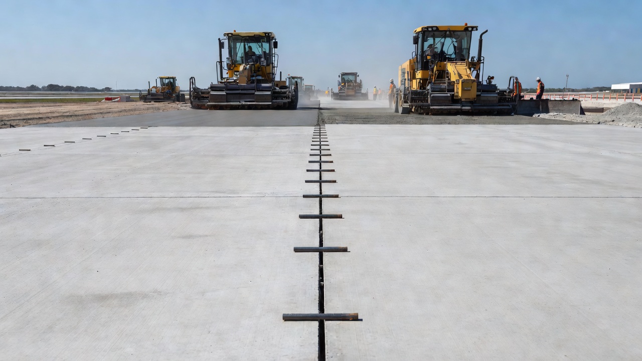
Construction Joints in Airport PCC Pavements
Airport Portland Cement Concrete (PCC) pavement construction joints are governed by FAA Advisory Circular AC 150/5370-10H (Standard Specifications for Construction of Airports) , Item P-501 (Cement Concrete Pavement), with requirements referenced by ICAO Annex 14 (Aerodromes, Volume I — Aerodrome Design and Operations) .
FAA P-501 specifies four joint types for airport pavements: transverse contraction joints at 15-20 foot spacing, saw-cut to 1/4 of slab depth and sealed; longitudinal construction joints at lane lines (12.5-25 foot spacing), tied with deformed bars or doweled; transverse construction joints at the end of each day’s placement, doweled for load transfer; and isolation joints at structures and changes in section, with full-depth compressible filler.
Dowel bar requirements at airport pavement construction joints per FAA P-501 are: diameter of 1 inch (25 mm) for slabs up to 12 inches thick, 1.25 inches (32 mm) for slabs over 12 inches thick; length of 18 inches (457 mm) ; spacing of 12 inches (300 mm) on center ; material of epoxy-coated steel per ASTM A775 or stainless steel; alignment tolerance of ±1/2 inch vertical and ±1 inch horizontal. Longitudinal tie bars are #5 (5/8 inch) to #6 (3/4 inch) deformed bars, Grade 60 (420 MPa), epoxy-coated, at 24-36 inch spacing.
Joint sealing requirements per FAA P-501 specify a sealant reservoir width of 1/4 to 3/8 inch, depth of 1/2 to 3/4 inch (saw-cut), sealant type of silicone per FAA P-605 or ASTM D5893 (or hot-poured per ASTM D1190/D3405/D6690), backer rod of closed-cell polyethylene sized 25% wider than the joint width, bond breaker tape at the reservoir bottom, and a sealant depth-to-width ratio of 2:1. Joint preparation for sealing requires joint walls to be cleaned and dry, with cleaning methods being sandblasting or high-pressure water approved by the FAA, followed by air blasting to remove all debris and dust. Acceptance criteria are no visible dust, oil, curing compound, or laitance. Bond testing follows ASTM C794 (peel test).
Quality control testing at joints per FAA P-501 includes concrete flexural strength (third-point loading) — minimum 650 psi (4.5 MPa) at 28 days, one test set per 5,000 square feet; dowel bar alignment — one in 20 bars checked against tolerances; joint sealant adhesion — one test per 500 feet per ASTM C794; and surface smoothness — maximum 1/8 inch in 16 feet (3 mm in 5 meters) full coverage.
ICAO Annex 14 provisions require that joints in rigid pavements be designed to minimize the effects of temperature and moisture changes, that load transfer efficiency (LTE) across joints measured by falling weight deflectometer (FWD) be at least 70%, that construction joints be planned to coincide with pavement marking or lane lines where possible, and that joint sealants be resistant to jet blast, fuel, and de-icing chemicals.
Differentiation from Structural Cracking
One of the most important inspection skills is correctly differentiating between three features that may appear similar on a concrete surface: a proper construction joint, a cold joint, and a structural crack. Each has distinct characteristics, implications, and required response.
Feature
Construction Joint (Planned)
Cold Joint (Unplanned)
Structural Crack
Origin
Deliberate, designed
Unintended delay in casting
Stress exceeding concrete tensile capacity
Location
Per design drawings (mid-span, low-shear zones)
Random, wherever delay occurred
Typically at regions of high moment or stress
Appearance
Clean line, often straight, consistent gap
Irregular line, color mismatch on either side
Variable width, may have branching
Surface prep
Roughened, cleaned, laitance removed
None or minimal
Not applicable
Reinforcement
Continuous through joint (designed)
May or may not be continuous
May have ruptured bars
Load transfer
Designed for shear (dowels or ties)
Poor to none
Some aggregate interlock if tight
Movement
May be designed to allow slip
None designed; unintended
Indicates ongoing distress
Leakage
Only if waterstop fails
Common — direct pathway
Varies with crack width
Acceptability
Acceptable if per design
Not acceptable — requires evaluation
Requires structural evaluation
The ACI 224R (Control of Cracking in Concrete Structures) provides crack width limits for various exposure conditions. For dry air or protective membrane, the maximum acceptable crack width is 0.016 inch (0.41 mm) . For humidity, moist air, or soil contact, the limit is 0.012 inch (0.30 mm) . For de-icing chemical exposure, the limit is 0.007 inch (0.18 mm) . For seawater or seawater spray, the limit is 0.006 inch (0.15 mm) . For water-retaining structures, the limit is 0.004 inch (0.10 mm) . Any crack exceeding these limits requires evaluation.
The evaluation protocol for a joint-like feature of unknown origin follows six steps. First, review the contract drawings to determine whether the feature is shown as a planned construction joint. Second, inspect the surface condition for evidence of laitance removal, roughening, or a keyway profile. Third, measure the width — cracks exceeding 0.016 inch require structural evaluation. Fourth, check for movement — crack width variation under load indicates an active structural crack. Fifth, core and test — extract a core through the interface and perform splitting tension or bond strength testing. Sixth, evaluate load transfer using FWD or plate load testing across the feature.
Repair of Failed Construction Joints
Repair methods for failed construction joints are selected based on the specific condition, the structural role of the joint, the presence of water leakage, and the extent of deterioration.
Epoxy Injection (Structural Repair)
Epoxy injection per ACI RAP-1 (Structural Crack Repair by Epoxy Injection) is used for structural restoration of cold joints and failed construction joints where the concrete is otherwise sound. The epoxy must meet ASTM C881 (Standard Specification for Epoxy-Resin-Base Bonding Systems for Concrete) , with Type I for non-load-bearing applications and Type IV for load-bearing structural repairs. Bond strengths after 14-day cure exceed 1,500 psi. Compressive yield at 7 days exceeds 10,000 psi for Type IV. Tensile strength at 7 days exceeds 7,000 psi.
Viscosity selection depends on joint width. Grade 1 (low viscosity, ≤2,000 cps) is used for joints narrower than 0.010 inch (0.25 mm). Grade 2 (medium, 2,000-10,000 cps) for joints 0.010-0.040 inch (0.25-1.0 mm). Grade 3 (non-sag gel) for joints wider than 0.040 inch (1.0 mm). Injection pressure is typically 40-200 psi for hand pumps or 200-1,000 psi for pneumatic pumps, with maximum pressure limited to avoid hydraulic fracturing of the concrete.
The injection procedure involves cleaning the joint surface, installing injection ports at 6-12 inch spacing along the joint, applying a surface cap seal (epoxy paste), injecting epoxy from the lowest port moving upward and outward, holding pressure until adjacent port shows epoxy, capping the injected port and moving to the next, allowing 24-72 hours cure depending on temperature, and grinding flush. Limitations include the requirement that the joint must be dry (or moisture-tolerant epoxy used), the joint must not be actively moving, and corrosion-induced cracking must not be epoxy-injected (corrosion continues internally).
Dowel Bar Retrofit
Dowel bar retrofit (DBR) is specified per FHWA Technical Advisory TA 5040.30 and ACPA DBR Guidelines for pavement joints with load transfer efficiency below 60% and joint faulting of 0.1-0.5 inch (3-12 mm) in structurally sound pavement. Specifications per ACPA guidelines: dowel diameter of 1.25-1.5 inches (32-38 mm) , dowel length of 18 inches (457 mm) , dowel spacing of 12 inches (300 mm) on center , slot dimensions of dowel diameter plus 2 inches width and depth to mid-slab, and patch material of non-shrink grout or rapid-set concrete with minimum 4,000 psi (28 MPa) compressive strength at 24 hours.
The procedure involves saw-cutting slots at designated locations perpendicular to the joint, breaking out concrete to required depth, cleaning the cavity, placing the dowel bar in the slot, filling with rapid-set patching material, finishing and curing, and testing load transfer by FWD. Performance data from a 10-year FHWA study shows load transfer efficiency increased from an average of 30% to over 80%, faulting reduced from an average of 0.25 inch to less than 0.05 inch, service life extended by 10+ years, and cost ranging from $200 to $400 per dowel.
Re-Concreting / Partial-Depth Repair
Re-concreting is used where the joint edge has failed with spalling, D-cracking, or extensive deterioration where epoxy injection or DBR alone is insufficient. The procedure involves saw-cutting a minimum of 6 inches (150 mm) back from the joint on both sides, removing deteriorated concrete to full depth or sound concrete, cleaning and preparing the surface, installing new dowels or tie bars as needed, placing new concrete using ASTM C928 rapid-hardening repair material or conventional concrete, forming a new joint plane or saw-cutting after curing, and sealing the joint.
Material options include rapid-set concrete per ASTM C928 Type III (4,000-6,000 psi compressive strength, 1-4 hour set time), high-early strength concrete (3,000 psi in 12 hours), polymer-modified concrete (5,000-8,000 psi, 2-6 hour set), and magnesium phosphate concrete (3,000-5,000 psi, 30-60 minute set).
Polyurethane Injection (Water Stop)
Polyurethane injection is used for leaking cold joints or construction joints with active water flow. Hydrophobic polyurethane reacts with water to form rigid foam, effective for high-flow leaks. Hydrophilic polyurethane swells on water contact to form a flexible gel, effective for intermittent leaks. The procedure involves drilling injection holes at 6-12 inch spacing along the joint, installing packers, injecting PU under pressure (50-300 psi), with water flow stopping within seconds to minutes. Typical gel time is 15-60 seconds, adjustable with catalyst. PU injection is the primary method for stopping active water leaks in below-grade structures, tunnels, and water-retaining structures.
Stitching (Reinforcement Addition)
Stitching adds reinforcement across a joint where existing continuity is insufficient. Bars are typically #5 to #8 (5/8 inch to 1 inch diameter), epoxy-grouted into drilled holes per ASTM C881 across the joint at calculated spacing. Injected depth is 12-24 bar diameters (12db-24db) . Pull-out testing must achieve at least 80% of yield strength. Stitching is used in structural walls, beams, or slabs with inadequate shear transfer across the joint plane.
Repair Selection Matrix
Joint Condition
Preferred Method
Alternative Method
Non-structural cold joint, no leakage
No repair needed (monitor)
Cosmetic overlay
Tight joint (<0.010 inch), no water
Epoxy injection (structural)
—
Wide joint (0.010-0.060 inch), no water
Epoxy injection (Type IV)
Rout and seal
Active water leak
Polyurethane injection
Crystalline repair
Failed pavement joint (LTE < 60%)
Dowel bar retrofit
Full-depth repair
Spalled joint edge, D-cracking
Partial-depth repair / re-concreting
Full slab replacement
Structural shear failure at joint
Stitching + epoxy injection
Member strengthening
Leaking waterstop / no waterstop
Crystalline waterstop system
Injection hose + grout
Key Standards References
Standard
Title
ACI 318-19
Building Code Requirements for Structural Concrete
ACI 224.3R-95
Joints in Concrete Construction
ACI 224R-19
Control of Cracking in Concrete Structures
ACI 546R
Concrete Repair Guide
ACI 562
Code Requirements for Assessment, Repair, and Rehabilitation of Existing Concrete Structures
ACI RAP-1
Structural Crack Repair by Epoxy Injection
ASTM C597
Standard Test Method for Pulse Velocity Through Concrete
ASTM C881
Standard Specification for Epoxy-Resin-Base Bonding Systems
ASTM C1583
Standard Test Method for Tensile Strength of Concrete Surfaces (Pull-off)
ASTM D4580
Standard Practice for Measuring Delaminations in Concrete Bridge Decks by Sounding
ASTM C42
Standard Test Method for Obtaining and Testing Drilled Cores and Sawed Beams of Concrete
AASHTO LRFD
Bridge Design Specifications (current edition)
FAA AC 150/5370-10H
Standard Specifications for Construction of Airports
ICAO Annex 14
Aerodromes, Volume I — Aerodrome Design and Operations
FHWA TA 5040.30
Concrete Pavement Joints
USBR MERL 12-17
Best Practices for Preparing Concrete Surfaces Prior to Repairs and Overlays
ICRI Guideline No. 03732
Selecting and Specifying Concrete Surface Preparation for Sealants, Coatings, and Polymer Overlays
Frequently Asked Questions
A construction joint is an intentional interface between two successive concrete placements, created when a concrete pour is stopped and later resumed. Per ACI 224.3R-95, construction joints are 'joints placed to define the extent of individual placements, generally in conformity with a predetermined joint plan.' They permit in-plane slip unless tied by design with reinforcement or dowels. Unlike contraction joints which are weakened planes for crack control, construction joints are designed as structural interfaces that must transfer shear, flexure, and axial forces across the joint plane.
A construction joint is a planned, designed interface with proper surface preparation including laitance removal, roughening to 1/4 inch amplitude, and continuous reinforcement across the joint. A cold joint is an unplanned interface caused by a delay exceeding the concrete's initial set time, with no surface preparation and poor or absent bond between the two batches. Per ACI 224.3R-95, cold joints result in bond strength reduction of 40-60% and permeability increases up to 10 times compared to properly prepared construction joints.
Construction joint preparation per ACI 318-19 Section 26.5.6 requires: (1) cleaning the hardened concrete surface of laitance, dirt, and contaminants; (2) intentionally roughening the surface to a full amplitude of approximately 1/4 inch (6 mm) where shear-friction is required; (3) prewetting the surface before new concrete placement; and (4) ensuring reinforcement extends continuously across the joint. Common preparation methods include green cutting (applied 2-6 hours after placement), sandblasting (ICRI CSP 3-7), and hydrodemolition (CSP 5-9, 10,000-40,000 psi water pressure).
Cold joints form when fresh concrete is placed against concrete that has already reached initial set, typically 2-4 hours after mixing depending on temperature, cement type, and water-cement ratio. In normal weather (70°F/21°C), the maximum acceptable delay is 30-45 minutes. In hot weather (90°F/32°C), the window reduces to 20-30 minutes. Common causes include concrete delivery delays (truck arrival intervals exceeding 30 minutes), equipment failure (pump breakdown, vibrator failure), inadequate crew size or planning, complex formwork slowing placement, and weather conditions accelerating set time.
Construction joints are inspected using chain drag sounding (ASTM D4580), hammer sounding on a 6-inch grid, and visual examination for laitance, efflorescence, cracking, and leakage. Pull-off bond testing per ASTM C1583 provides quantitative bond strength measurement, with ACI 562 requiring minimum 200 psi (1.4 MPa) tensile bond for structural repairs. Ultrasonic pulse velocity (ASTM C597) detects debonding zones when velocity drops below 3,000 m/s. Core sampling (ASTM C42) provides direct observation of the joint interface and allows laboratory bond strength testing.
Repair methods depend on the joint condition. Structural repair uses epoxy injection (ASTM C881 Type IV, bond strength exceeding 1,500 psi) for joints with adequate confinement. Active water leaks are stopped with polyurethane injection (hydrophilic or hydrophobic resins). Pavement joints with load transfer efficiency below 60% receive dowel bar retrofit (1.25-1.5 inch diameter bars at 12 inch spacing, targeting LTE above 80%). Spalled joint edges require partial-depth re-concreting with rapid-set materials (minimum 4,000 psi compressive strength). Leaking waterstops in water-retaining structures are repaired with crystalline waterproofing systems.
Construction joint inspection follows standards including ASTM D4580 (chain drag and hammer sounding), ASTM C1583 (pull-off bond testing, minimum 200 psi per ACI 562), ASTM C597 (ultrasonic pulse velocity), and ASTM C42 (core sampling and testing). For bridge decks, FHWA mandates annual chain drag inspection. For airport pavements, FAA AC 150/5370-10H P-501 specifies dowel bar alignment tolerances of +/- 1/2 inch vertical and joint sealant adhesion testing per ASTM C794. ACI 318-19 Section 26.5.6 establishes mandatory construction joint requirements for structural concrete.
Construction joint waterproofing systems include PVC waterstops (4-12 inch widths, up to 200 ft hydrostatic head, heat-welded splices), hydrophilic waterstops (bentonite-based swelling up to 16x dry volume or urethane-based swelling to 350%), crystalline waterproofing systems (chemical reaction forming insoluble crystals in concrete pores, self-sealing capability, up to 50% less cost than PVC), and injection hose systems (pre-placed hollow tubes for post-cure grout injection). Selection depends on hydrostatic pressure, joint movement expectations, and chemical exposure conditions.
Need concrete structure inspection services?
TarmacView provides comprehensive concrete structure inspection solutions including construction joint assessment, cold joint detection, bond testing, and condition reporting. Contact our team of experienced civil engineers.
Transverse joints are sawed or formed cuts across PCC pavement slabs at regular spacing (typically 4.5-6 m for JPCP) to control transverse cracking from thermal...
Debonding is defined as the loss of adhesion at the interface between a concrete overlay or repair material and the existing concrete substrate, or between an e...
Joint sealants are materials placed in pavement joints to prevent water and incompressible material infiltration, protecting the subbase and preventing joint sp...
37 min read
Pavement Maintenance
Concrete Pavement
+3
Cookie Consent We use cookies to enhance your browsing experience and analyze our traffic. See our privacy policy.