Map Cracking
Map cracking (also called crazing) is a network of shallow, fine, interconnected cracks on the concrete surface forming an irregular pattern. In FHWA LTPP, map ...
30 min read
Concrete Defects
Pavement Distress
+3
D-cracking is a pattern of closely spaced crescent-shaped cracks near joints, edges, and cracks in PCC pavements, caused by freeze-thaw deterioration of susceptible coarse aggregate. It is a progressive, irreversible distress affecting airport runways in cold climates.
D-cracking, formally designated as Durability Cracking (Distress Type JCP 2 in the FHWA Long-Term Pavement Performance (LTPP) Distress Identification Manual), is a distinctive form of concrete pavement deterioration caused by the freeze-thaw failure of susceptible coarse aggregate particles. The term “D-cracking” originated from the word “durability” — it is a durability-related cracking phenomenon that specifically targets the aggregate component of the concrete rather than the cement paste matrix.
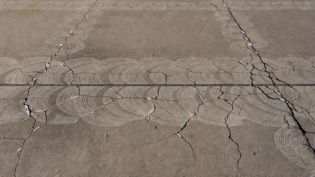
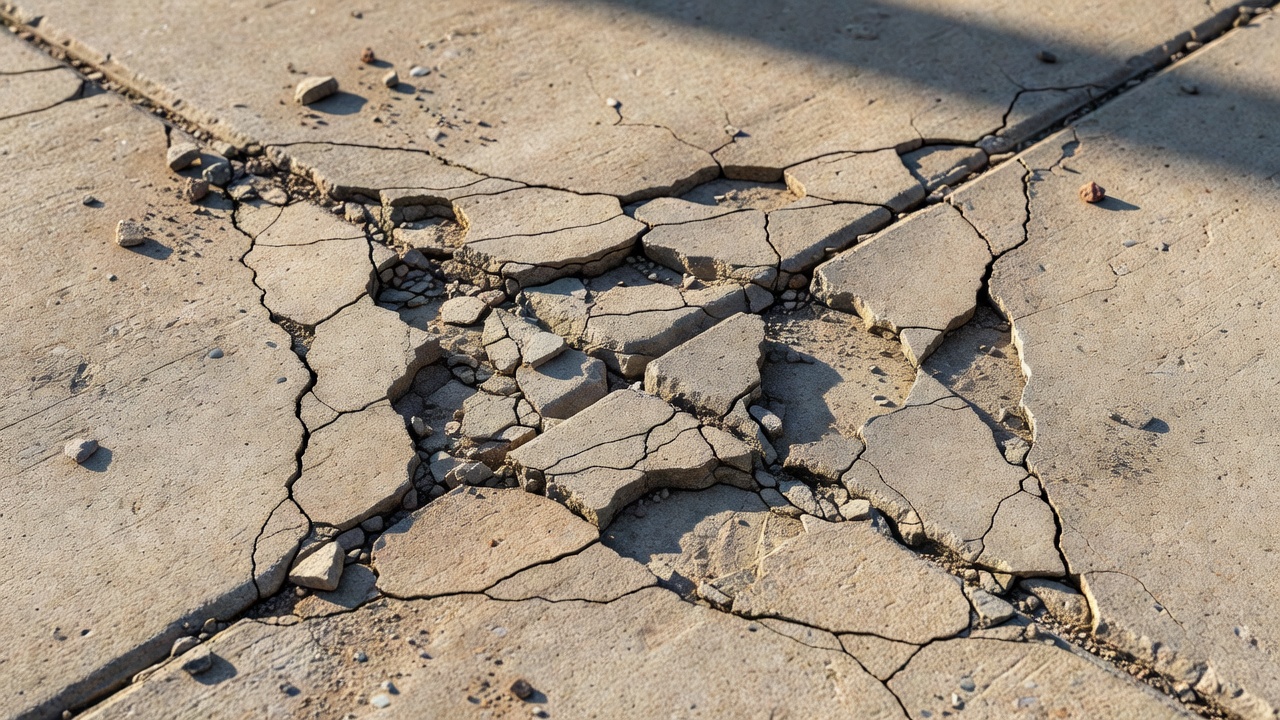
The visual appearance of D-cracking is highly characteristic and diagnostic. It presents as a pattern of closely spaced, crescent-shaped, or hairline cracks that form parallel to joints, cracks, and free edges of the concrete slab. The cracks typically initiate at slab corners — the intersection points of transverse and longitudinal joints — and progressively extend along the joint line. The cracking pattern has been described as resembling a series of nested arcs or a scalloped border running alongside the joint. In the early stages, the cracks are tight and barely visible to the naked eye, often requiring close inspection in good lighting conditions.
As the distress progresses, the affected area expands outward from the joint face into the slab interior. The pattern is rarely random; it follows the geometry of the slab boundaries. A dark staining or discoloration of the concrete surface frequently precedes or accompanies the visible cracking. This staining is caused by the accumulation of deicing chemicals, moisture, and fine particulate debris in the incipient micro-cracks, and it serves as an early warning sign that D-cracking is active beneath the surface. In advanced stages, the cracking intensifies to the point where individual aggregate particles become exposed and pop out, creating a rough, pitted surface texture at the joint edge.
The FHWA LTPP distress identification manual defines D-cracking as “closely spaced crescent-shaped hairline cracking pattern” that occurs “adjacent to joints, cracks, or free edges; initiating in slab corners.” The severity classification system is defined across three levels:
| Severity Level | Visual Characteristics | Quantifiable Indicators |
|---|---|---|
| Low | Cracks are tight, hairline width; no loose or missing pieces; no patching in affected area | Crack widths typically < 0.5 mm; no measurable material loss |
| Moderate | Cracks are well-defined and easily visible; some small pieces are loose or have become displaced | Crack widths 0.5–2 mm; loose fragments present but area intact |
| High | Well-developed cracking pattern with significant loose or missing material; displaced pieces up to 0.1 m² may have been patched | Crack widths > 2 mm; material loss evident; patching present |
The measurement protocol for D-cracking requires recording both the number of affected slabs and the square meters of affected area at each severity level. The slab and affected area severity rating is based on the highest severity level present for at least 10 percent of the area affected.
The fundamental mechanism driving D-cracking is the freeze-thaw deterioration of coarse aggregate particles within the concrete. This is a physical materials-related distress (MRD) mechanism, classified by FHWA under “Freeze-Thaw Deterioration of Aggregate” with an observed time frame of 10 to 25 years after construction. The mechanism involves three interrelated processes: water absorption into the aggregate pore structure, ice formation under freezing conditions, and internal pressure generation that exceeds the aggregate tensile strength.
Coarse aggregate particles are not monolithic solids. They contain an internal pore structure that varies widely depending on the rock type, geological origin, and weathering history. Certain aggregates — particularly those with high microporosity — can absorb significant quantities of water when the concrete is exposed to moisture from rainfall, snowmelt, groundwater capillary rise, or condensation. The aggregate pores range in size from gel pores (nanometer scale) to capillary pores (micrometer scale) to macroscopic voids. The critical pore size range for freeze-thaw susceptibility is approximately 0.1 to 10 micrometers — pores large enough to hold freezable water but small enough to generate damaging hydraulic pressures during ice formation.
The concept of critical saturation is central to understanding D-cracking initiation. When the aggregate pore system is less than approximately 85 to 90 percent saturated with water, freezing can occur without damage because the expanding ice has space to grow into unfilled pores. However, when the saturation level exceeds this critical threshold, the water has no room to expand as it transforms to ice (which occupies approximately 9 percent more volume than liquid water). This generates hydraulic pressure within the aggregate particle according to the Powers-LaDu model of freeze-thaw damage. As the ice front advances through the pore network, unfrozen water is pushed ahead of the freezing front, creating additional osmotic pressure due to concentration gradients in the pore solution.
When the combined hydraulic and osmotic pressures exceed the tensile strength of the aggregate particle, internal fracturing occurs. This fracturing typically initiates at the aggregate-paste interface and propagates through the aggregate body. With each successive freeze-thaw cycle, the cracks grow longer and wider, eventually extending through the surrounding cement paste to the pavement surface. The process is progressive and irreversible — once an aggregate particle begins to deteriorate, each subsequent winter adds more damage.
The FHWA Tech Brief on Concrete Paving Mixture Durability (FHWA-HIF-16-033) explains that “freezing and thawing of susceptible coarse aggregates results in fracturing or excessive dilation of aggregate” and that this process typically manifests after 10 to 25 years of service. The delay reflects the time required for the aggregate to absorb sufficient moisture to reach critical saturation. In arid climates or well-drained pavements, the distress may never develop even with susceptible aggregates. In cold, wet climates — typical of northern airport locations — the conditions for D-cracking are optimized.
The environmental factors that accelerate D-cracking include: high annual precipitation, poor drainage, standing water on the pavement surface, use of deicing chemicals (which increase the degree of saturation through osmotic effects), high groundwater table, and frequent freeze-thaw cycling (more than 50 cycles per year in severe climates). The application of deicing chemicals amplifies the mechanism by increasing the degree of concrete saturation to levels that approach or exceed the critical saturation threshold, and by amplifying osmotic pressure through changes in the pore solution chemistry.
Not all coarse aggregates are susceptible to D-cracking. The susceptibility is determined by the pore structure characteristics of the aggregate, which are functions of its mineralogical composition, geological origin, and physical properties. Aggregates with high absorption, high porosity, and a significant proportion of pores in the 0.1 to 10 micrometer diameter range are most prone to freeze-thaw deterioration. The rock types most commonly associated with D-cracking susceptibility include certain cherts, shales, sandstones, limestones, dolomites, and some graywackes — particularly those that have undergone secondary mineralization or weathering that has created microporosity.
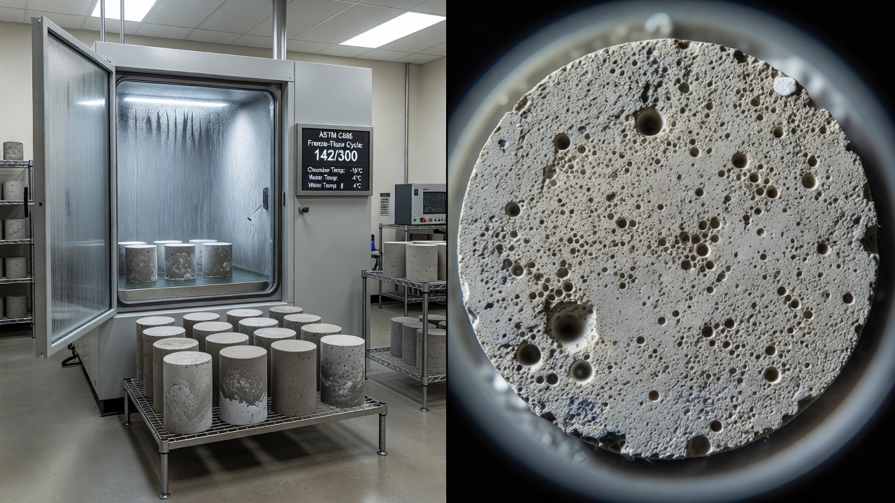
The primary standardized test for evaluating aggregate freeze-thaw susceptibility is ASTM C666 — Standard Test Method for Resistance of Concrete to Rapid Freezing and Thawing. This test exposes concrete specimens (typically beams measuring 75 × 100 × 400 mm) to repeated cycles of freezing and thawing in a controlled laboratory environment. The test has two procedures:
| Parameter | Procedure A | Procedure B |
|---|---|---|
| Freezing medium | Water | Air |
| Thawing medium | Water | Water |
| Cooling rate | Controlled | Controlled |
| Cycle duration | 2–5 hours | 2–5 hours |
| Target cycles | 300 cycles | 300 cycles |
Testing is typically conducted for 300 cycles or until the specimen reaches a durability factor (DF) below a specified threshold. The durability factor is calculated as:
DF = (P × N) / M
Where:
The relative dynamic modulus of elasticity (P) is determined by measuring the fundamental transverse frequency of the concrete beam specimen before and after freeze-thaw exposure, using the procedure in ASTM C215. As internal micro-cracking develops, the dynamic modulus decreases, providing a quantitative measure of damage progression.
| Durability Factor Range | Classification | D-Cracking Risk |
|---|---|---|
| DF ≥ 80 | Excellent freeze-thaw resistance | Low risk |
| 60 ≤ DF < 80 | Good freeze-thaw resistance | Moderate risk |
| 40 ≤ DF < 60 | Fair freeze-thaw resistance | High risk |
| DF < 40 | Poor freeze-thaw resistance | Very high risk |
A durability factor below 60 is generally considered to indicate a high susceptibility to D-cracking, and many transportation agencies specify a minimum DF of 70 or 80 for aggregates used in concrete pavement exposed to freeze-thaw conditions. However, the ASTM C666 test has limitations: it is time-consuming (taking 3 to 6 months to complete), requires specialized equipment, and the freeze-thaw cycling rate (one cycle every 2 to 5 hours) does not replicate natural environmental conditions.
The Iowa Pore Index (IPI) test was developed as a rapid screening method to identify D-cracking susceptible aggregates. It measures the volume of water absorbed by an oven-dried aggregate sample under controlled pressure conditions over a specified time period. The test is significantly faster than ASTM C666, requiring only a few hours to complete.
The IPI test procedure involves:
Research conducted by the Iowa Department of Transportation established that the IPI correlates fairly well with aggregate freeze-thaw performance measured by ASTM C666. Aggregates with an Iowa Pore Index above a certain threshold (typically IPI > 2.0 mL for the 1-minute reading) are considered susceptible to D-cracking. The test has been adopted by several state DOTs as a quality control measure for aggregate acceptance.
Petrographic examination (ASTM C295) is used to identify potentially susceptible aggregate types through microscopic analysis of thin sections. Petrographers look for evidence of microporosity, secondary mineralization, clay coatings, and reactive mineral phases that may indicate freeze-thaw susceptibility. This method is qualitative but provides valuable information about the geological characteristics of the aggregate source.
Absorption and specific gravity testing (ASTM C127) provides indirect indications of susceptibility. Aggregates with absorption greater than 1.5 to 2.0 percent are generally considered potentially susceptible, although this threshold varies by aggregate type and agency specifications.
The soundness test (ASTM C88) uses alternate immersion in saturated sodium sulfate or magnesium sulfate solution followed by oven drying to accelerate the simulation of freeze-thaw damage. However, the correlation between soundness loss and field freeze-thaw performance is not always reliable, and this test is increasingly considered less predictive than direct freeze-thaw testing or pore index measurements.
D-cracking is a progressive distress that follows a predictable pattern of deterioration if left unaddressed. Understanding this progression is essential for pavement management decisions and repair timing. The evolution from initial micro-cracking to full material disintegration typically spans several years, passing through clearly identifiable stages.
Stage 1 — Incipient Cracking (Years 10–15 typically): The first visible signs of D-cracking appear as dark staining along joint lines and at slab corners. This staining is caused by moisture and deicing chemicals penetrating the incipient micro-cracks at the aggregate-paste interface. No surface cracking is yet visible, but the staining pattern follows future crack lines. The concrete surface at this stage remains structurally sound.
Stage 2 — Crescent Crack Development (Years 12–18 typically): Fine, closely spaced crescent-shaped cracks become visible alongside joints and at slab corners. The cracks are tight (hairline width) and form a repeating arcing pattern that parallels the joint face. The cracking typically extends 100 to 300 mm from the joint into the slab interior. The concrete remains intact with no loose material. At this stage, the distress is classified as Low severity per FHWA LTPP definitions.
Stage 3 — Crack Propagation and Widening (Years 15–22 typically): The crescent-shaped cracks become more defined and wider. The affected zone expands further from the joint. Individual cracks begin to intersect, and small fragments of concrete become loose at the surface. The dark staining intensifies. The surface texture becomes rough in the affected areas. This stage corresponds to Moderate severity classification.
Stage 4 — Material Loss and Spalling (Years 18–25 typically): The cracking pattern is well-developed across the affected zone. Significant amounts of loose and missing material appear at the joint edge and slab corners. The joint itself becomes compromised as the D-cracked concrete breaks away. This creates a form of secondary spalling — joint edge deterioration that is distinct from primary joint spalling caused by other mechanisms. Displaced pieces up to 0.1 m² may be present. This stage is classified as High severity.
Stage 5 — Structural Deterioration (Years 20+ typically): In advanced cases where multiple slab corners have undergone severe D-cracking with material loss, the structural integrity of the slab at the joint can be compromised. Load transfer efficiency across the joint is reduced, leading to faulting (vertical displacement across the joint). Water infiltration through the deteriorated joint exacerbates subgrade softening and pumping. Full-depth slab replacement may become necessary.
The transition from D-cracking to spalling is important for distress identification. True joint spalling (Distress Type JCP 6 and 7 in the LTPP manual) is caused by traffic loading, incompressible materials in the joint, or freeze-thaw deterioration of the cement paste and manifests as cracking, chipping, or fraying of the concrete at the joint edges. D-cracking-induced spalling, by contrast, is a secondary consequence of aggregate deterioration — the cracks form first in the slab interior adjacent to the joint, and material loss occurs later as the cracked concrete breaks away under traffic loading. The distinction matters for repair strategy: treating D-cracking-induced spalling as simple joint spalling will not address the underlying aggregate deterioration.
D-cracking presents specific challenges for airport concrete pavement because of the unique operational and safety requirements of aviation facilities. Airport runways, taxiways, and aprons are constructed with portland cement concrete (PCC) in accordance with FAA Advisory Circular 150/5320-6G (Airport Pavement Design and Evaluation). These pavements are designed for a 20- to 40-year service life, but D-cracking can significantly reduce this lifespan if susceptible aggregates are used.
The FAA requires air-entrained concrete for all airport pavement exposed to freezing temperatures. However, as noted earlier, air entrainment alone does not prevent D-cracking — it protects the paste but not the aggregate. The FAA Advisory Circular 150/5370-10H (Standards for Specifying Construction of Airports) provides aggregate quality requirements, including limits on absorption, soundness loss, and freeze-thaw durability factor. Item P-501 (for concrete pavement) specifies that coarse aggregate must meet freeze-thaw testing requirements for the specific climate zone.
The Iowa Airport Pavement Management System identifies D-cracking as a specific distress type in its Pavement Condition Index (PCI) survey procedures. The system notes that “Durability cracking (D-Cracking) is caused by the concrete’s inability to withstand environmental factors such as freeze-thaw cycles” and that it is most commonly observed in older concrete pavements (15+ years) constructed before modern aggregate testing and specification practices were implemented.
The operational implications of D-cracking on airport pavements are significant:
| Operational Impact | Description | Safety Concern |
|---|---|---|
| Foreign Object Debris (FOD) | Loose concrete fragments from advanced D-cracking become potential FOD hazards | High — FOD can damage aircraft engines and tires |
| Surface roughness | Material loss at joints creates uneven surface texture | Moderate — affects ride quality and braking |
| Joint deterioration | Compromised joints reduce load transfer efficiency | High — can lead to slab faulting and structural failure |
| Water infiltration | Cracked joints allow water penetration to subgrade | Moderate — accelerates subgrade weakening |
| Reduced pavement life | Progressive deterioration shortens service life | Operational/economic — requires earlier rehabilitation |
Pavement condition surveys at airports in cold-climate regions (such as the Upper Midwest, Northeast United States, Canada, Northern Europe, and high-altitude airports) routinely include D-cracking assessment. The survey protocols follow ASTM D5340 (Standard Test Method for Airport Pavement Condition Index Surveys) and FAA Advisory Circular 150/5380-6C (Guidelines and Procedures for Maintenance of Airport Pavements). D-cracking is identified and rated separately from other distress types, and its presence influences the overall PCI calculation.
For airport pavement management, the detection of D-cracking at Low severity is a critical decision point. If caught early, surface sealers or joint sealant maintenance can slow moisture ingress and delay progression. Once the distress reaches Moderate or High severity, localized repairs may be necessary, and the affected slabs should be scheduled for partial or full-depth replacement within the capital improvement program. The FAA recommends that airport operators track D-cracking progression over time through periodic PCI surveys (typically every 3 to 5 years) to inform rehabilitation planning.
Correct identification of D-cracking is essential for appropriate pavement management decisions. Several other concrete distress types can appear similar to an untrained eye, but each has distinct characteristics in terms of visual pattern, location, cause, and progression.
| Distress Type | Visual Pattern | Typical Location | Primary Cause | Key Distinguishing Feature |
|---|---|---|---|---|
| D-Cracking | Closely spaced crescent-shaped hairline cracks | Adjacent to joints, cracks, and free edges; initiates at slab corners | Freeze-thaw deterioration of coarse aggregate | Crescent pattern parallels joint; dark staining precedes cracking |
| Map Cracking | Random interconnected network of fine cracks | Over entire slab surface or large areas | Alkali-silica reaction (ASR), drying shrinkage, or freeze-thaw of paste | No preferential orientation at joints; covers slab interior |
| Joint Spalling | Cracking, chipping, fraying at joint edges | Directly on the joint edge | Traffic loading, incompressibles, paste freeze-thaw | Material loss at joint face itself, not adjacent slab interior |
| Corner Break | Single diagonal crack from joint intersection | Slab corner, typically at 45-degree angle to traffic | Traffic loading combined with inadequate support | Single crack line, not multiple closely spaced cracks |
| Longitudinal Cracking | Single crack parallel to pavement centerline | Mid-slab, wheel path, or random | Load-related fatigue, slab curling, or construction joints | Single crack line, not multiple crescent-shaped cracks |
| Transverse Cracking | Single crack perpendicular to pavement centerline | Across slab width | Thermal or drying shrinkage, load-related fatigue | Single straight or slightly curved crack across slab |
| Popouts | Small conical depressions where aggregate is exposed | Random individual locations | Freeze-thaw of individual aggregate particles near surface | Isolated, not a connected crack pattern |
The FHWA Distress Identification Manual emphasizes that D-cracking is classified under the Cracking category (not Surface Defects), and it explicitly differentiates it from map cracking and joint spalling. The manual notes that D-cracking can be distinguished from map cracking by its crescent-shaped pattern and its location adjacent to joints, cracks, or free edges — map cracking is distributed across the slab surface without preferential orientation at joints.
One of the most common misidentifications is confusing D-cracking with alkali-silica reaction (ASR) distress. Both can produce cracking at joints and both involve aggregate particles. However, ASR cracking is typically a pattern or map cracking distributed across the slab surface, often accompanied by exudate (a white or translucent gel that exudes from cracks), joint closure from expansion, and in advanced cases, blowups (sudden compressive failure at joints). D-cracking produces a distinctive crescent pattern specifically along joints, rarely produces visible exudate, and does not cause joint closure or blowups.
The distinction between D-cracking and freeze-thaw scaling of the cement paste is also important. Scaling is a surface defect (Distress Type JCP 8b) that involves flaking or peeling of the surface mortar, exposing coarse aggregate but without the crescent-shaped cracking pattern. Scaling is caused by freeze-thaw deterioration of the paste rather than the aggregate, and it typically requires air entrainment deficiencies.
D-cracking detection combines visual inspection, specialized testing, and advanced technologies to identify the distress at various stages of development. Early detection is critical because the distress is irreversible and mitigation options diminish as severity increases.
The primary detection method is visual inspection conducted as part of a Pavement Condition Index (PCI) survey following ASTM D5340 or ASTM D6433 standards. During visual inspection, the surveyor walks the pavement surface and examines each slab for signs of distress. D-cracking is identified by looking for:
The inspector records the number of affected slabs and the square meters of area affected at each severity level. The ASTM standard requires that the inspector rate the severity based on the highest level present for at least 10 percent of the affected area.
The chain drag method is a simple yet effective acoustic technique for detecting delaminated or deteriorated concrete. A heavy steel chain is dragged across the pavement surface while the inspector listens for changes in the sound produced. Sound, intact concrete produces a clear, ringing tone. Deteriorated or delaminated concrete produces a hollow, drum-like sound because the subsurface cracking separates the concrete into layers that vibrate independently. Chain dragging can detect D-cracking before surface cracks become visible, particularly when the aggregate deterioration has created internal fracturing beneath an intact surface layer.
Ground penetrating radar is a non-destructive geophysical technique that uses electromagnetic pulses to image subsurface conditions. GPR can detect D-cracking by identifying changes in the dielectric properties of the concrete caused by increased moisture content and cracking in the joint-adjacent zone. High-frequency antennas (1.0 to 2.6 GHz) provide sufficient resolution to detect the thin, closely spaced cracks characteristic of D-cracking. GPR surveys can cover large pavement areas quickly and provide continuous subsurface profiles showing the extent of deterioration.
Impact echo (IE) is a non-destructive test method that uses mechanical impact (typically a small steel sphere) to generate stress waves in the concrete. The reflected waves are analyzed to determine the thickness, integrity, and internal condition of the slab. D-cracking creates a zone of reduced wave velocity and increased signal attenuation in the affected area. Impact echo can identify the depth of deterioration, which is important for determining whether partial-depth or full-depth repair is appropriate.
Modern inspection technologies, including computer vision and machine learning systems such as TarmacView, use high-resolution cameras mounted on survey vehicles to capture continuous pavement surface imagery. Deep learning algorithms trained on thousands of labeled distress images can automatically detect and classify D-cracking patterns, measure crack width and affected area, and assign severity ratings. AI-powered systems offer several advantages over manual inspection:
For definitive diagnosis, concrete core samples can be extracted from the affected area and examined in the laboratory. The cores are cut through the D-cracked zone and examined visually and microscopically. D-cracking in cores appears as:
Petrographic examination (ASTM C856 — Standard Practice for Petrographic Examination of Hardened Concrete) provides definitive confirmation of the distress mechanism by showing that the cracking path goes through susceptible aggregate particles rather than through the cement paste.
Because D-cracking is caused by freeze-susceptible coarse aggregate, prevention must focus on aggregate selection, mix design, and construction practices that minimize the risk of freeze-thaw deterioration. Prevention is far more cost-effective than repair, and the measures must be implemented during the design and construction phases.
The most effective prevention strategy is to select coarse aggregate that is inherently resistant to freeze-thaw deterioration. This requires:
The FHWA Tech Brief recommends that aggregates for paving concrete exposed to freeze-thaw conditions should have a durability factor of at least 70 when tested in accordance with ASTM C666, and the concrete should have a water-to-cementitious materials ratio (w/cm) of 0.45 or less to reduce overall permeability.
While air entrainment does not directly prevent D-cracking (because the distress originates inside aggregate particles, not in the paste), it is still essential for overall freeze-thaw durability of the concrete pavement. The entrained air voids protect the cement paste from freeze-thaw damage, which otherwise would compound the distress from aggregate deterioration. ACI 201 (Guide to Durable Concrete) specifies air content requirements based on exposure class and nominal maximum aggregate size:
| Nominal Maximum Aggregate Size | Exposure Class F1 | Exposure Class F2 and F3 |
|---|---|---|
| 19 mm (3/4 in) | 5.0% | 6.0% |
| 25 mm (1 in) | 4.5% | 6.0% |
| 37.5 mm (1-1/2 in) | 4.5% | 5.5% |
| 50 mm (2 in) | 4.0% | 5.0% |
The air content should be measured on fresh concrete samples at the point of placement, and the air-void system parameters (spacing factor, specific surface) should be verified through hardened concrete air-void analysis (ASTM C457).
Reducing the permeability of the concrete matrix limits the amount of moisture that can reach the aggregate particles, thereby slowing the rate of water absorption that leads to critical saturation. Low permeability is achieved through:
Maintaining effective joint sealants prevents moisture infiltration through the joint into the aggregate at the slab edge. While this does not stop D-cracking caused by moisture entering through the concrete surface or from below the slab, it reduces the concentration of moisture at the joint face where D-cracking typically initiates. Regular joint sealant inspection and replacement (every 5 to 10 years depending on sealant type) is a recommended preventive maintenance practice.
Proper pavement drainage reduces the moisture available for aggregate absorption. This includes:
In some cases, susceptible aggregates can be blended with durable aggregates to reduce the overall D-cracking risk. Blending dilutes the concentration of susceptible particles, but it does not eliminate the risk entirely because even a small percentage of freeze-susceptible particles can initiate cracking. Most agencies limit the use of marginal aggregates in blended stockpiles or require additional testing to verify that the blend meets durability requirements.
D-cracking is an irreversible progressive distress — once initiated, it will continue to develop regardless of treatment. Repair strategies therefore focus on managing the progression, restoring pavement function, and extending service life rather than curing the underlying aggregate deterioration. The appropriate repair strategy depends on the severity and extent of the distress.
At Low severity, where cracks are tight and no material loss has occurred, the priority is to slow moisture ingress into the affected zone:
These treatments do not halt D-cracking but can extend the time before the distress reaches Moderate severity by 5 to 10 years. The FAA Advisory Circular 150/5380-6C recommends crack and joint sealing as maintenance activities for pavements with Low severity distress.
At Moderate severity, where loose fragments are present but the deterioration is limited to the upper portion of the slab, partial-depth repair (PDR) is the standard treatment. The FHWA Partial-Depth Repair Guide defines PDR as “removing an area of deteriorated concrete that is limited to the top one-third of the slab thickness and replacing it with appropriate repair material.”
The partial-depth repair process for D-cracking:
The key to successful PDR for D-cracking is removing all deteriorated concrete within the repair limits. If aggregate below the repair depth is already deteriorating, the distress will reappear at the patch boundary within a few years.
At High severity, where significant material loss has occurred and the structural integrity of the slab is compromised, full-depth slab replacement is the recommended treatment. The FHWA Full-Depth Repair Guide classifies D-cracking as a justification for full-depth repair when it reaches Medium or High severity.
Full-depth repair involves:
Full-depth replacement is expensive but provides a permanent solution for the affected slab, assuming the replacement concrete contains freeze-thaw durable aggregate. Multiple adjacent slabs with D-cracking may be replaced as a group to minimize saw-cut boundaries and improve ride quality.
Some agencies have used milling and overlay strategies for pavements with extensive D-cracking. The deteriorated surface layer is milled to a depth of 50 to 100 mm, removing the worst of the D-cracked concrete, and a new concrete or asphalt overlay is placed. This approach is typically used when D-cracking affects a high percentage of slabs and individual repairs are not cost-effective.
It is important to recognize that repair of D-cracking does not stop the underlying deterioration mechanism in adjacent areas. The freeze-susceptible aggregate throughout the pavement remains susceptible, and repaired areas will eventually develop new deterioration as adjacent aggregate particles continue to degrade. A successful pavement management program for D-cracking involves:
For airport pavements, the FAA Advisory Circulars provide the regulatory framework for determining when repairs are necessary based on PCI values, distress severity, and operational requirements. Pavements with extensive High severity D-cracking that creates FOD hazards or compromises structural capacity may require expedited rehabilitation regardless of the planned maintenance schedule.
TarmacView provides AI-powered pavement inspection solutions that automatically detect and classify distresses like D-cracking, spalling, and joint deterioration in concrete airport pavements. Schedule a demonstration to see how our technology can enhance your pavement management program.
Map cracking (also called crazing) is a network of shallow, fine, interconnected cracks on the concrete surface forming an irregular pattern. In FHWA LTPP, map ...
Edge cracking in asphalt pavements refers to crescent-shaped or fairly continuous longitudinal cracks that intersect the pavement edge and are located within 0....
Alligator cracking — also called fatigue cracking — is an interconnected crack pattern resembling alligator skin that indicates structural failure of the asphal...