Delamination
Delamination is the separation of concrete layers along a plane approximately parallel to the surface, creating subsurface voids detectable by hammer sounding, ...
37 min read
Concrete Defects
Bridge Inspection
+3
Debonding is defined as the loss of adhesion at the interface between a concrete overlay or repair material and the existing concrete substrate, or between an externally bonded fiber-reinforced polymer (FRP) system and the concrete surface. This interfacial separation creates a planar void that produces a characteristic hollow sound when impacted and represents a primary failure mode for bonded concrete overlays, patch repairs, whitetopping, and FRP strengthening systems used on airport pavements, bridge decks, and building structures.
Debonding is defined as the loss of adhesive bond at the interface between two materials that were intentionally bonded together during construction. In concrete infrastructure, this most commonly refers to the separation between a concrete overlay or repair material and the existing concrete substrate, or between a fiber-reinforced polymer (FRP) strengthening system and the concrete surface to which it is adhered. The American Concrete Institute (ACI) defines debonding in ACI 546.3R as “the separation of a repair or overlay material from the concrete substrate at the interface,” distinguishing it from cohesive failure within the materials themselves.
The bond mechanism at the interface involves three distinct components: mechanical interlock, where cement paste from the new material penetrates surface irregularities of the substrate; chemical adhesion, where hydration products from the new cementitious material react with the exposed surface of the old concrete; and thermodynamic adhesion (Van der Waals forces), which depends on the surface energy and cleanliness of the substrate. ACI 546.3R-14 (“Guide for Materials Selection in Concrete Repair”) describes the interface as a three-phase composite: the existing concrete substrate, the repair or overlay material, and the interfacial transition zone (ITZ) that forms between them. The ITZ is typically 10-50 micrometers thick and represents the weakest link in the bonded system.
When the tensile or shear stress at the interface exceeds the bond strength, debonding initiates as a micro-crack at a point of stress concentration. Under continued loading or environmental cycling, this crack propagates along the interface, forming a planar void that may extend over a significant area. The debonded interface crack typically propagates in a mixed-mode (Mode I + Mode II) fracture pattern, where both tensile opening stresses and shear sliding stresses contribute to crack growth.
The critical strain energy release rate (Gc) at the interface is a material property that governs debonding propagation. For concrete-to-concrete interfaces, values typically range from 50 to 150 J/m² depending on surface preparation quality. For FRP-to-concrete interfaces, the fracture energy is typically lower, ranging from 300 to 700 N/mm for the interfacial fracture energy per unit width (Gf as defined in ACI 440.2R). The bond strength is commonly quantified through pull-off testing per ASTM C1583/C1583M, which measures the tensile stress required to separate a bonded overlay or repair from the substrate. The minimum acceptable pull-off bond strength specified by most codes (including the International Concrete Repair Institute, ICRI Guideline 03732) is 1.0 MPa (145 psi) for interior applications and 1.5 MPa (220 psi) for exterior applications subject to freeze-thaw exposure.
Debonding results from the combination of inadequate interfacial bond development during construction and stresses that exceed the developed bond strength during service. The causes span material properties, construction practices, and environmental exposure conditions.
The single most common cause of debonding is inadequate surface preparation of the concrete substrate. The ICRI Guideline 03732 (“Guide for Selecting and Specifying Concrete Surface Preparation for Sealers, Coatings, Polymer Overlays, and Concrete Repair”) establishes Concrete Surface Profile (CSP) ratings from CSP 1 (very smooth) to CSP 10 (extremely rough). For bonded concrete overlays, a minimum profile of CSP 5 to CSP 9 is required, corresponding to a surface roughness amplitude of 0.4 to 1.5 mm (0.016 to 0.060 inches). This profile is typically achieved through shotblasting, scarification, hydro-demolition, or heavy abrasive blasting.
The substrate must also be saturated surface dry (SSD) at the time of overlay placement — a condition specified by ACI 546.3R and FAA Advisory Circular 150/5370-10 Item P-501. An excessively dry substrate will absorb water from the fresh overlay, creating a water-starved interface with poor hydration. An overly wet substrate creates a water film at the interface that prevents proper adhesion. The surface must be free of laitance (the weak, chalky layer of fine particles that forms on fresh concrete), curing compounds, oil, grease, dust, and other contaminants. ACI 546.3R specifies that the substrate should be prepared to achieve a minimum surface tensile strength of 1.0 MPa (145 psi) by pull-off testing before the overlay is placed.
Differential drying shrinkage is the most common debonding stress mechanism for concrete overlays. When a new cementitious overlay is placed on an existing concrete substrate, the overlay undergoes drying shrinkage as it loses moisture to the environment. The existing substrate, having already undergone most of its shrinkage, restrains this movement through the bonded interface. This restraint induces tensile stress in the overlay and shear stress at the interface. The magnitude of shear stress depends on the shrinkage differential between the two materials, the modulus of elasticity of the overlay, the interface bond stiffness, and the restraint factor provided by the substrate.
Typical drying shrinkage of a concrete overlay ranges from 400 to 800 microstrain (0.04% to 0.08%) depending on the water-cement ratio, aggregate type, curing conditions, and ambient relative humidity. For a bonded overlay of 100 mm (4 inches) thickness, the restrained shrinkage can generate interface shear stresses of 0.5 to 2.0 MPa (70 to 290 psi) — values that approach or exceed the bond strength achievable with poor surface preparation. This explains why debonding often appears within the first 28 to 90 days after overlay placement before traffic loading is applied. ASTM C157/C157M provides the standard test method for measuring length change (drying shrinkage) of hardened concrete.
Thermal incompatibility between the overlay material and the substrate creates stress at the interface during temperature changes. The coefficient of thermal expansion (CTE) for conventional Portland cement concrete ranges from 7 to 12 × 10⁻⁶ /°C. When the overlay and substrate have different CTE values (which commonly occurs when a rapid-setting repair material or polymer-modified concrete is used alongside conventional concrete), a temperature change of 30°C (54°F) can generate interface stresses of 0.3 to 1.0 MPa (45 to 145 psi). This is particularly problematic for airfield pavements, which experience rapid temperature changes from solar heating during the day to radiational cooling at night, and from jet blast heating during aircraft operations.
FAA Advisory Circular 150/5380-6C (“Guidelines and Procedures for Maintenance of Airport Pavements”) notes that thermal incompatibility is a frequent cause of repair and overlay failure in airport pavements, particularly when rapid-strength concrete or polymer concrete patching materials are used adjacent to conventional PCC pavement. The ICRI Guideline 03734 (“Guide for Selecting and Applying Materials for Concrete Repair”) provides a thermal compatibility index for repair materials, recommending that the CTE of the repair material should be within ±2 × 10⁻⁶ /°C of the substrate CTE.
Corrosion of reinforcing steel can induce debonding through two mechanisms. First, corrosion products (rust) occupy a volume 2 to 6 times greater than the original steel, generating expansive pressure that can cause the concrete cover to separate from the underlying steel layer — a related but distinct condition from the interfacial debonding discussed here. Second, corrosion at the interface level (where the overlay meets a steel-reinforced substrate) can produce delamination-related debonding as the rust products physically wedge the interface apart.
The corrosion rate, expressed in µm/year of steel section loss, can be measured by linear polarization resistance (LPR) per ASTM G59 or by concrete resistivity per AASHTO T 358 (the Wenner four-probe method). A corrosion rate above 0.5 µA/cm² is considered high risk for corrosion-induced distress. The presence of chlorides at the interface above the corrosion threshold (typically 0.15% total chloride by weight of cement for the onset of corrosion, or 0.025% water-soluble chloride per ACI 222R) accelerates this process significantly.
Additional factors that contribute to debonding include inadequate curing of the overlay (premature moisture loss reduces the developed bond strength), improper bonding agent application (either too thin to provide coverage or too thick creating a weak layer), early traffic loading before the overlay has achieved sufficient bond strength, and freeze-thaw cycling at the interface where moisture accumulates. Moisture-sensitive debonding is particularly problematic for FRP systems, where water penetrating to the FRP-concrete interface can break the epoxy bond through hydrolytic degradation of the adhesive layer. ACI 440.2R-17 (“Guide for the Design and Construction of Externally Bonded FRP Systems for Strengthening Concrete Structures”) warns that moisture intrusion at the FRP interface reduces the glass transition temperature (Tg) of the epoxy and can lead to accelerated creep rupture of the adhesive.
Debonding and delamination produce identical audible symptoms (hollow sound when tapped) and share similar consequences (loss of composite action, spalling risk, water ingress), but they are fundamentally different in mechanism and location.
Debonding occurs at a constructed interface between two intentionally bonded materials — at the interface between a concrete overlay and the existing substrate, between a patch repair and the surrounding concrete, or between an FRP sheet and the concrete surface. The bond failure is adhesive (failure at the interface between the two materials) rather than cohesive (failure within one material). In pull-off testing per ASTM C1583, an adhesive failure at the repair-substrate interface with no material left on either surface is classified as debonding.
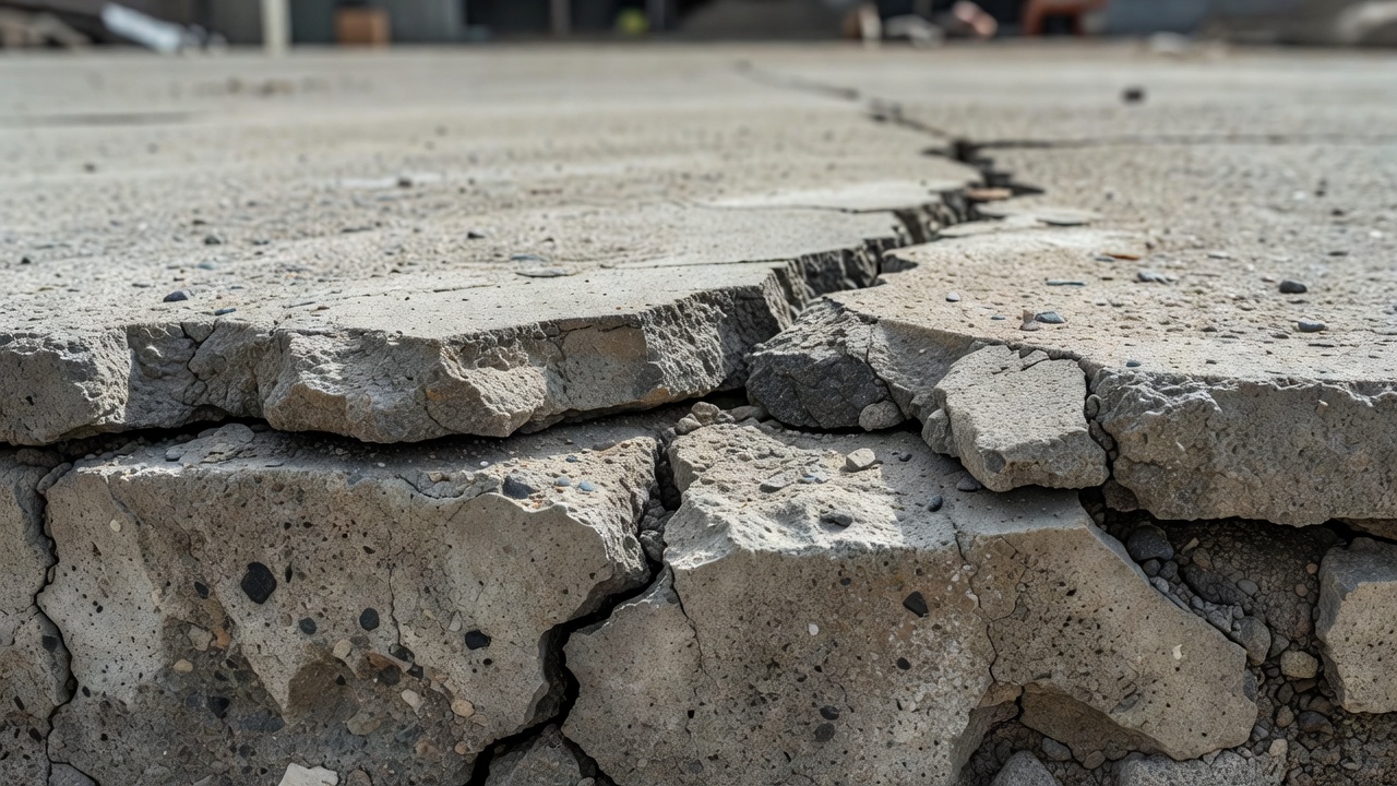
Delamination occurs within a single homogeneous concrete layer, typically at or near the plane of the reinforcing steel. The primary mechanism is corrosion-induced expansive pressure that causes the concrete cover to separate from the underlying concrete mass at the level of the reinforcing bars. Delamination can also be caused by freeze-thaw damage (D-cracking at joints) or ASR (alkali-silica reaction) expansive gel formation. The separation plane in delamination is typically parallel to the surface at a depth of 20-50 mm (the depth of the top reinforcement mat), whereas debonding occurs precisely at the constructed material interface regardless of depth.
| Characteristic | Debonding | Delamination |
|---|---|---|
| Failure Plane | At constructed interface between two materials | Within homogeneous concrete, typically at rebar depth |
| Primary Cause | Inadequate bond development or overstress | Corrosion, freeze-thaw, ASR |
| Location | Overlay/substrate, FRP/concrete, patch/host | Within bridge decks, slabs, beams |
| Appearance on Core | Clean separation at material boundary | Separation through concrete, often with rust staining |
| Depth | Variable, corresponds to interface depth | Typically 20-50 mm (cover depth) |
| Repair Approach | Re-establish bond at interface | Remove and replace separated concrete layer |
The practical distinction matters for repair strategy: debonding requires re-establishing the adhesive bond at the interface through methods like epoxy injection (per ASTM C881) or overlay removal and replacement with proper surface preparation, while delamination requires removing the separated concrete down to sound material and replacing it with repair material. However, the detection methods for both conditions are identical — hammer sounding (ASTM D4580), chain drag, infrared thermography (ASTM D4788), and impact-echo (ASTM C1383) all identify planar separations regardless of whether the separation is debonding or delamination.
Debonding detection relies on the principle that a planar void beneath the surface creates a different response to acoustic, thermal, or stress-wave excitation compared to sound, fully bonded material. The choice of detection method depends on the accessibility of the surface, the depth of the interface, the area to be surveyed, and the required accuracy.
The hammer sounding test (also called tap testing, sounding, or percussion testing) is the most widely used method for debonding detection. The inspector taps the concrete surface with a geologist’s hammer, ball-peen hammer, or sounding hammer at regular intervals (typically 300 mm or 12-inch spacing for detailed surveys, 600 mm or 24-inch for general surveys per ASTM D4580). Sound, bonded concrete produces a sharp, ringing, metallic sound due to efficient elastic wave transmission through the material. Debonded or delaminated concrete produces a dull, hollow, drum-like sound because the air gap prevents efficient wave transmission. The frequency content of the response differs: sound concrete produces high-frequency energy above 2 kHz, while debonded areas produce lower-frequency energy concentrated below 500 Hz. This acoustic difference can be quantified using digital acoustic analysis systems that record the hammer impact sound and classify it by frequency content.

The chain drag test uses a heavy steel chain (typically 3 to 5 feet long, weighing 10-15 pounds) that is dragged across the pavement surface while the inspector listens for changes in the sound it produces. The chain drag is specified by FAA Advisory Circular 150/5380-6C and ASTM D5340 (the standard for Airport Pavement Condition Index surveys) as the primary sounding method for airfield pavement condition surveys. The chain drag can cover large areas quickly — an experienced inspector can survey 500-1000 m² per hour — making it the most productive manual sounding method. The chain drag test is particularly effective for detecting debonding in concrete overlay systems because the chain’s mass provides sufficient energy to excite the debonded panel into vibration.
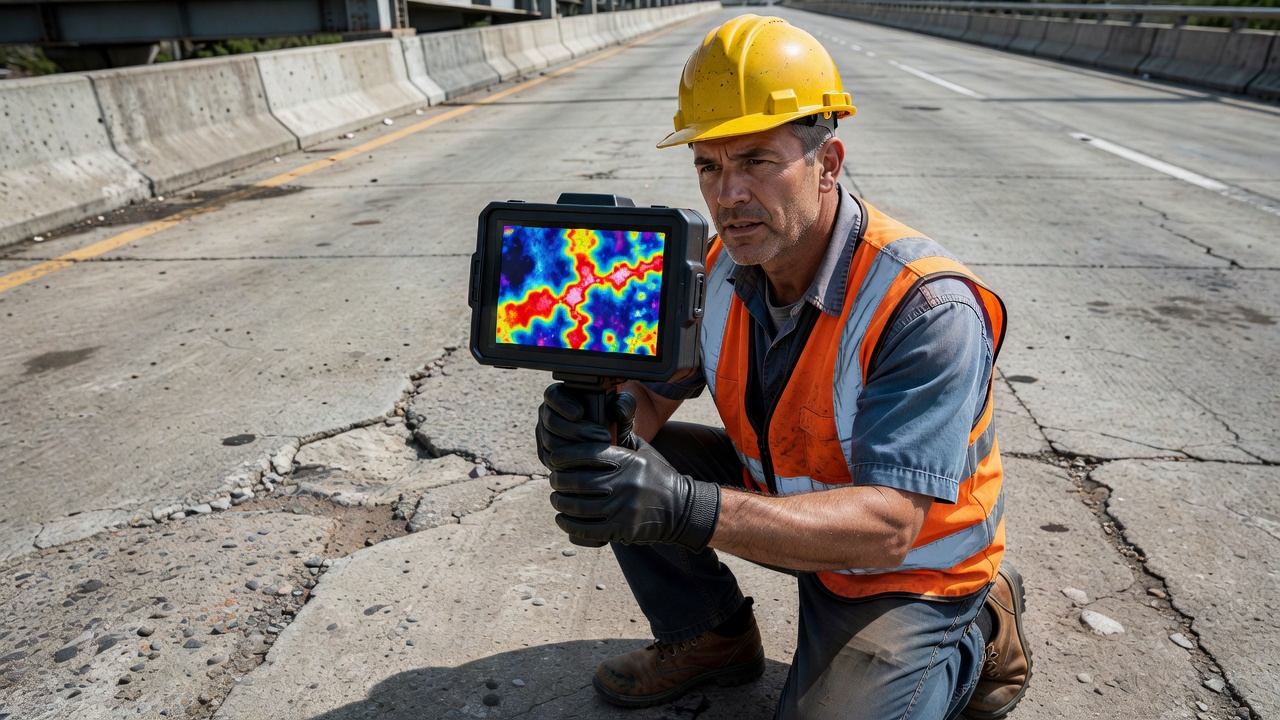
Infrared thermography (IRT) is a non-contact, rapid-scanning method that detects debonding by measuring surface temperature differentials caused by the insulating effect of the air gap beneath a debonded overlay or FRP. During solar heating (typically between 10:00 AM and 2:00 PM on a clear, sunny day), the surface temperature over a debonded area increases 1-5°C more than the surrounding sound concrete because the air gap insulates the surface from conductive heat loss to the substrate. During nighttime cooling (typically 2-4 hours after sunset), the debonded area appears cooler because the insulating air gap prevents heat stored in the surface layer from being replenished by conduction from the substrate.
ASTM D4788 (“Standard Test Method for Detecting Delaminations in Bridge Decks Using Infrared Thermography”) provides the standard protocol for IRT of concrete bridge decks and overlays. The test requires a minimum temperature differential of 0.5°C between debonded and sound areas for reliable detection, though modern high-sensitivity cameras (with NETD or Noise Equivalent Temperature Difference of 0.03°C or better) can detect smaller differentials. The maximum detectable debonding depth depends on the overlay thickness: for a 50 mm (2-inch) overlay, debonding can be reliably detected; for overlays thicker than 150 mm (6 inches), the temperature differential at the surface becomes too small for reliable IRT detection. FAA Advisory Circular 150/5370-10 recognizes IRT as an acceptable method for quality assurance of bonded overlays on airport pavements.
IRT advantages over sounding methods include full-field coverage (a single thermal image covers 50-200 m² depending on elevation), permanent digital record of results, and speed (survey rates of 5000-10000 m² per hour are achievable from a vehicle-mounted system). The primary limitation is that IRT detects only disbonds within the near-surface region (typically within the first 100-150 mm of depth) and cannot reliably detect deep debonding at the overlay-substrate interface if the overlay is thick.
Impact-echo (IE) is a stress-wave-based NDT method that uses a mechanical impact (typically a small steel ball or spring-loaded impactor) to generate low-frequency stress waves that propagate through the concrete. The waves reflect from internal interfaces (including debonded air gaps) and the far-surface of the element, producing a frequency spectrum that can be analyzed to determine both the presence and the depth of debonding. ASTM C1383 (“Standard Test Method for Measuring the P-Wave Speed and the Thickness of Concrete Plates Using the Impact-Echo Method”) provides the standard test protocol. For debonding detection, the impact-echo method can determine the depth of the debonded interface by analyzing the dominant frequency in the response waveform — shallow debonding produces high-frequency peaks, while deep debonding produces lower-frequency peaks.
The impact-echo method is particularly valuable for FRP debonding detection because it can identify the interface between the FRP and concrete even through the FRP layer, and it can distinguish between shallow debonding (at the FRP-concrete interface) and deep substrate damage. The typical frequency range for FRP debonding detection is 10-30 kHz, requiring specialized impactors and sensors.
The detection method selection depends on the specific application:
| Application | Primary Method | Confirmation Method | Standard |
|---|---|---|---|
| Airport PCC pavement overlay | Chain drag (ASTM D5340) | Cores (ASTM C42) | FAA AC 150/5380-6C |
| Bridge deck overlay | Hammer sounding | IR thermography, cores | ASTM D4580, ASTM D4788 |
| FRP strengthening | Impact-echo | Thermal imaging, pull-off | ACI 440.2R, ASTM C1383 |
| Patch repairs | Hammer sounding | Pull-off test (ASTM C1583) | ICRI 03732 |
| Thin bonded overlays (< 50 mm) | IR thermography | Chain drag, cores | ASTM D4788 |
Definitive confirmation of debonding requires concrete coring per ASTM C42/C42M (“Standard Test Method for Obtaining and Testing Drilled Cores and Sawed Beams of Concrete”). Cores are extracted at locations identified as debonded by NDT methods, and the interface is visually examined. The core photograph is the definitive record: a clean separation at the interface without any material adhered to either surface confirms adhesive debonding failure. The minimum core diameter for interface evaluation is typically 50 mm (2 inches), though 100 mm (4 inches) is preferred for thicker overlays.
Concrete overlays (also called bonded concrete overlays, resurfacing, or whitetopping) are placed directly on existing concrete pavement to restore structural capacity, improve ride quality, and extend service life. The bonded interface is critical because it enables composite structural action — the overlay and existing slab acting together as a single structural section. The composite section has significantly greater structural capacity than the two layers acting independently (the section modulus is proportional to the square of the total thickness when the layers are fully bonded). The bond is achieved through mechanical interlock between the fresh overlay concrete and the roughened, clean, SSD-condition existing surface.
FAA Advisory Circular 150/5370-10 Item P-501 (“Standard Specifications for Construction of Airports: Portland Cement Concrete Pavement”) specifies the requirements for bonded concrete overlays on airfield pavements. The existing surface must be cold milled or shotblasted to remove a minimum of 6 mm (0.25 inches) of surface material, achieving CSP 5-7 surface texture. The surface is then cleaned by high-pressure water blasting (minimum 20,000 psi) followed by air blasting to remove all debris and standing water. A cement slurry bonding agent (1:1 cement-to-water ratio by weight) is brush-applied immediately ahead of overlay placement.
The FHWA Concrete Overlay Guide (FHWA-HIF-18-032) distinguishes between two types of bonded concrete overlays: BCO (Bonded Concrete Overlay) for thicknesses of 50-175 mm (2-7 inches) on PCC pavements, and BCOA (Bonded Concrete Overlay on Asphalt) for thicknesses of 100-200 mm (4-8 inches) on asphalt pavements (also called whitetopping). For BCO on PCC, the existing pavement condition determines overlay feasibility: the existing pavement must have less than 15% structural distress (pumping, faulting more than 6 mm, slab cracking more than moderate severity per ASTM D5340) to ensure that debonding stresses from differential movement remain within acceptable limits.
Debonding in concrete overlays typically initiates at discontinuities in the substrate — at existing cracks, joints, or deteriorated areas where the surface profile deviates from ideal. The debonded area then propagates outward from these initiation points due to traffic loading fatigue and thermal cycling. The debonding rate depends on the interface shear stress magnitude and the number of load applications. Research by the FHWA Long-Term Pavement Performance (LTPP) program indicates that debonded areas in bonded overlays typically grow at a rate of 5-15% of the initially debonded area per year under moderate traffic, accelerating to 15-30% per year under heavy traffic loading.
The critical time for debonding is the first 90 days after overlay placement. During this period, the overlay undergoes its primary drying shrinkage while the bond strength is still developing. The minimum acceptable bond strength for overlay acceptance, specified by ICRI Guideline 03732, is 0.7 MPa (100 psi) average with no individual reading below 0.5 MPa (70 psi) within 7 days of placement, increasing to 1.0 MPa (145 psi) at 28 days.
Externally bonded FRP (fiber-reinforced polymer) systems are used to strengthen concrete structures by bonding carbon fiber, glass fiber, or aramid fiber sheets or plates to the concrete surface using epoxy adhesives. The FRP debonding is a critical failure mode that governs the design of FRP strengthening in ACI 440.2R-17 (“Guide for the Design and Construction of Externally Bonded FRP Systems for Strengthening Concrete Structures”).
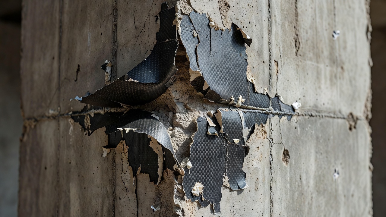
FRP debonding manifests in two primary modes: plate-end (PE) debonding and intermediate crack-induced (IC) debonding. PE debonding occurs at the termination point of the FRP laminate, where high interfacial shear and normal (peeling) stresses develop because the FRP abruptly terminates. This mode is prevented by extending the FRP past the point of zero moment by a sufficient development length (typically 300-600 mm or 12-24 inches per ACI 440.2R). IC debonding initiates at a flexural or shear crack in the concrete, where the crack opening creates a local stress concentration in the FRP laminate at the crack location. The stress then propagates along the FRP-concrete interface toward the FRP end in a progressive peeling failure.
The debonding strain limit in ACI 440.2R-17 limits the maximum usable strain in the FRP to εfd = 0.41√(f’c / (nef Ef tf)) but no greater than 0.9 εfu (where εfu is the ultimate rupture strain of the FRP). This limit is designed to prevent IC debonding as a governing failure mode. For a typical carbon FRP (CFRP) with modulus of 165 GPa (24 × 10⁶ psi) and thickness of 1.0 mm (0.039 inches), the debonding strain limit is approximately 0.005 to 0.007 (5,000 to 7,000 microstrain), which is about 30-40% of the ultimate strain of the FRP. This design provision ensures that the FRP-concrete bond remains intact under service conditions.
Detection of FRP debonding requires specialized methods because the FRP sheet masks the visual appearance of the interface. Impact-echo testing (as described in Section 4) is the most common method, as the stress waves penetrate the FRP and reflect from the debonded interface. Infrared thermography is also effective for FRP systems because the thin FRP layer (typically 1-3 mm thick) has low thermal mass and rapidly transfers heat to the interface, creating measurable temperature differentials within minutes of active heating. Post-installation inspection of FRP systems per ACI 440.2R requires a 100% tap test of all installed FRP surfaces within 7 days of installation, with any debonded areas exceeding 5% of the total FRP area requiring repair.
The bond line quality is evaluated through pull-off testing per ASTM C1583, with a minimum acceptable value of 1.0 MPa (145 psi) specified by ACI 440.2R for FRP-to-concrete bond. The failure mode is recorded: failure in the concrete substrate (desired, indicating that the concrete is weaker than the bond), adhesive failure at the FRP-epoxy interface, adhesive failure at the concrete-epoxy interface (undesired, indicating debonding), or cohesive failure within the epoxy. The presence of adhesive failure at either interface at pull-off values below 1.0 MPa indicates inadequate bond development and requires FRP removal and re-installation.
Concrete patch repairs — both partial-depth and full-depth — depend on achieving and maintaining bond at the patch-host concrete interface. The interface in a patch repair is a three-dimensional perimeter surface rather than a planar horizontal surface: the vertical faces of the patch cavity and the bottom (in partial-depth repairs) or the prepared substrate surface (in full-depth repairs). Debonding in patch repairs represents the separation of the repair material from the host concrete along these interface surfaces.
The bond mechanism in patch repairs follows the same principles as overlay bonding, but the stress state is more complex because of the restrained geometry of the patch. The patch material is surrounded by host concrete on all sides, which provides full restraint against shrinkage. This produces multi-axial tensile stresses at the interface, with maximum stress concentrations at the patch corners and edges. The shrinkage differential between the repair material and the host concrete generates interface shear stresses that can exceed the bond strength, particularly when high-shrinkage repair materials are used.
ACI 546.3R-14 (“Guide for Materials Selection in Concrete Repair”) specifies that surface preparation for patch repairs should achieve a CSP 7-9 profile (roughening amplitude of 0.6-1.5 mm), achieved through light jackhammering using a maximum 15 kg (30 lb) jackhammer to avoid microcracking the substrate below the repair perimeter. The saw-cut perimeter of the patch should extend a minimum of 25 mm (1 inch) beyond the visible edge of the distressed area into sound concrete. The sides of the repair cavity should be cut perpendicular to the surface or undercut (slightly wider at the bottom than the top) to provide mechanical interlock against vertical debonding forces.
For partial-depth repairs (typically 25-75 mm or 1-3 inches deep — the FAA standard per AC 150/5380-6C), debonding occurs most commonly at the horizontal interface between the patch bottom and the prepared substrate. The bond is evaluated by pull-off testing per ASTM C1583 at a minimum of 3 locations per 100 m² of repair area. The acceptance criteria per ICRI Guideline 03732 are: minimum individual pull-off value of 0.5 MPa (70 psi), and average of all tests of 0.7 MPa (100 psi) or greater.
For full-depth repairs (complete slab replacement), the critical interface is the vertical face where the repair concrete meets the existing slab at the saw-cut perimeter. Full-depth repairs commonly have dowel bars installed across the joint (per FAA Item P-501 for airfield pavements, with dowels spaced at 300 mm centers and placed at mid-slab depth) to provide load transfer. Debonding at the vertical interface in full-depth repairs is less common than in partial-depth repairs but can occur due to inadequate vibration during concrete placement, which leaves a honeycombed interface zone, or premature saw-cutting which initiates a crack that propagates along the interface.
Debonding has cascading consequences for structural performance and durability. The immediate effect is loss of composite action between the overlay and substrate. For a bonded concrete overlay system, the flexural stiffness (EI) of the composite section is proportional to the cube of the total thickness when fully bonded. When debonding occurs, the two layers act independently, each carrying load separately. For a 100 mm overlay on a 200 mm existing slab, the fully bonded section has an effective thickness of 300 mm. After debonding, the system behaves as two separate slabs of 100 mm and 200 mm. The moment of inertia reduction is from bh³/12 for the composite to (b × 100³/12 + b × 200³/12) for the separated layers — a reduction factor of approximately 0.35, meaning the structural capacity is reduced by approximately 65%.
Water ingress is the second critical consequence of debonding. The planar void created by debonding provides a continuous pathway for water to travel laterally beneath the overlay, bypassing joint seals and surface drainage. The water accumulates in the debonded void, creating a saturated interface zone that accelerates freeze-thaw damage and corrosion of any embedded steel. The trapped water also induces hydraulic pressure under traffic loading — as a tire passes over a debonded area, the overlay deflects, compressing the water-filled void. The hydraulic pressure can exceed 1 MPa (145 psi) under heavy aircraft loading (Airplane Design Group V or VI per FAA), driving the water to the overlay edges and pumping it out, carrying fines with it in a process called erosion pumping. This pumping action progressively widens the debonded area and carries debris into the interface, further preventing re-bonding.
FOD (Foreign Object Debris) generation is a particular concern for airfield pavements. A debonded overlay that has not been detected can eventually break through to the surface under traffic loading, creating spalls and loose fragments that become FOD — a serious hazard for aircraft engines and tires. FAA Advisory Circular 150/5380-6C specifically highlights overlay debonding as a FOD-prone condition requiring immediate attention on runways, taxiways, and apron areas.
The corrosion acceleration cycle triggered by debonding is self-perpetuating. Water entering the debonded interface carries chlorides (from deicing chemicals or marine exposure) and oxygen to the interface zone. If the substrate contains reinforcing steel, chlorides reach the steel surface and initiate corrosion. The corrosion products (rust) expand and further wedge the interface apart, enlarging the debonded area. The enlarged debond allows more water and chlorides to enter, accelerating corrosion. This positive feedback loop can cause total loss of the overlay in 2-5 years if undetected, versus an expected service life of 15-25 years for a properly bonded overlay.
Debonding inspection is integrated into pavement condition surveys and bridge inspection protocols at multiple levels. The Pass/Fail approach (debonded or not debonded) is typically supplemented by area quantification for condition rating and repair prioritization.
ASTM D5340 (“Standard Test Method for Airport Pavement Condition Index Surveys”) includes debonding as a distress type for concrete overlays, classified within the “patching” and “surface distress” categories. The survey protocol specifies chain drag as the primary detection method for overlay debonding, with the following severity levels:
The PCI (Pavement Condition Index) deduct value for debonding increases nonlinearly with severity and extent. The PCI deduct curve for debonding in ASTM D5340 shows that high-severity debonding covering 30% of a pavement section produces a deduct value exceeding 50 (on a 0-100 scale), corresponding to a pavement rating of “poor.”
FHWA’s National Bridge Inspection Standards (NBIS) and the AASHTO Manual for Bridge Element Inspection include debonding in the evaluation of bridge deck elements. The element-level inspection (per AASHTO MBEI-2019) classifies debonding as a defect within Element 12 (Concrete Deck) with condition states:
| Infrastructure Type | Inspection Method | Minimum Frequency | Standard |
|---|---|---|---|
| Airport PCC overlay | Chain drag + visual | Annual for PCI survey | ASTM D5340, FAA AC 150/5380-6C |
| Airport concrete repair | Hammer sounding | 30 and 90 days post-installation | FAA AC 150/5370-10 |
| Bridge deck overlay | IR thermography + sounding | Every 24 months (NBIS) | ASTM D4788, NBIS |
| FRP strengthening | Tap test + pull-off | 7 days post-installation, then annually | ACI 440.2R |
| Whitetopping (BCOA) | Chain drag + cores | Every 12 months for first 3 years | FHWA HIF-18-032 |
Recent advances in computer vision and machine learning have enabled automated debonding detection from surface imagery and drone-based thermal surveys. Deep learning models trained on labeled sounding data can classify pavement surface conditions in high-resolution images by identifying characteristic cracking patterns (map cracking, crescent-shaped cracks) that correlate with subsurface debonding. Thermal image analysis using convolutional neural networks (CNNs) can automatically segment thermal images into debonded and sound regions with accuracy exceeding 85% in controlled studies. TarmacView’s inspection platform integrates automated debonding detection from drone and vehicle-mounted camera surveys, providing quantified debonding extent maps with severity classification for overlay and repair condition assessment.
The repair strategy for debonding depends on the extent, severity, cause, and location of debonding, as well as the type of bonded system (concrete overlay, FRP, or patch repair).
For small, isolated debonded areas (less than 10% of the total bonded area) where the interface is not contaminated with debris or corrosion products, epoxy injection can re-establish the bond. The procedure follows ASTM C881 (“Standard Specification for Epoxy-Resin-Base Bonding Systems for Concrete”), which specifies epoxy type and grade requirements. The injection process involves:
Epoxy injection can restore bond strength to 80-100% of the original design bond strength when applied to clean, dry debonded interfaces. The method is not effective when the interface is contaminated with oil, dirt, or corrosion products, as the epoxy bonds to the contaminant rather than the concrete surfaces. The maximum debonding depth for effective epoxy injection is approximately 50 mm (2 inches) — deeper debonds create injection paths that are too long for complete filling.
For debonding exceeding 10% of the bonded area, or for debonded areas where the interface is contaminated, removal and replacement of the debonded portion is the standard approach. The procedure per FAA AC 150/5380-6C and ICRI Guideline 03732 follows these steps:
For extensive debonding exceeding 30% of the overlay area, complete overlay removal and replacement is typically more cost-effective than selective repair. The remaining bonded material will act as stress concentration points if partially removed, and the patching of multiple small areas creates many new interface perimeters that are potential future debonding initiation points.
FRP debonding repair is governed by ACI 440.2R-17, Chapter 12. The procedure for repairing debonded FRP:
The protocol for FRP debonding detection during service life includes annual tap test surveys of the entire FRP surface, with interim surveys after any significant overload event (earthquake, impact, high wind). If debonding exceeds 5% of the FRP area at any survey, immediate repair is required per ACI 440.2R.
For debonded overlays where removal and replacement is not feasible (e.g., overlays on structural bridge components where removal would expose the structure to traffic), shear connectors can provide mechanical reattachment. Stainless steel or galvanized dowels (12-16 mm diameter, 150-200 mm long) are installed by drilling through the overlay into the substrate, cleaning the holes, and grouting the dowels in place with epoxy grout conforming to ASTM C881. The dowels are typically placed at 600 mm (24-inch) centers in a grid pattern across the debonded area, with edge distance of 150 mm minimum from the debonded boundary. The reinstated bond capacity through shear connectors is typically 30-50% of the original bonded capacity per connector, so the number of connectors must be calculated based on the expected interface shear stress at ultimate load.
| Standard | Title | Relevance to Debonding |
|---|---|---|
| ACI 546.3R | Guide for Materials Selection in Concrete Repair | Bond mechanisms, surface preparation, interface strength |
| ACI 440.2R | Guide for Design and Construction of Externally Bonded FRP | FRP debonding strain limits, IC debonding, development length |
| ASTM D4580 | Standard Practice for Measuring Delaminations in Concrete Bridge Decks by Sounding | Hammer sounding protocol, grid spacing requirements |
| ASTM D4788 | Standard Test Method for Detecting Delaminations in Bridge Decks Using Infrared Thermography | IRT procedure, minimum temperature differential requirements |
| ASTM C1383 | Standard Test Method for Measuring the P-Wave Speed and Thickness of Concrete Plates by Impact-Echo | Impact-echo method for debonding depth determination |
| ASTM C1583 | Standard Test Method for Tensile Strength of Concrete Surfaces and the Bond Strength of Concrete Repair and Overlay Materials | Pull-off testing, bond acceptance criteria |
| ASTM C881 | Standard Specification for Epoxy-Resin-Base Bonding Systems for Concrete | Epoxy injection materials for debonding repair |
| ICRI 03732 | Guide for Selecting and Specifying Concrete Surface Preparation | CSP ratings, minimum surface preparation for bond |
| FAA AC 150/5380-6C | Guidelines and Procedures for Maintenance of Airport Pavements | Debonding inspection for airfield pavements, chain drag method |
| FAA AC 150/5370-10 | Standards for Specifying Construction of Airports (Item P-501) | Overlay construction specifications, bond requirements |
| ASTM D5340 | Standard Test Method for Airport Pavement Condition Index Surveys | Debonding PCI deduct curves, severity classification |
| FHWA HIF-18-032 | Concrete Overlay Guide | Bonded overlay design, debonding prevention |
TarmacView helps infrastructure inspectors detect and document debonding defects using AI-powered analysis of surface imagery. Schedule a demo to see how automated debonding detection can streamline your inspection program.
Delamination is the separation of concrete layers along a plane approximately parallel to the surface, creating subsurface voids detectable by hammer sounding, ...
Spalling is the breaking, chipping, or loss of concrete material at pavement joints, edges, or cracks — a critical defect in airport runways, taxiways, bridges,...
Raveling is the progressive dislodgement and loss of aggregate particles from the pavement surface due to binder aging, oxidation, or poor compaction. In airpor...