Differential settlement is uneven vertical displacement of pavement or structural elements due to non-uniform subgrade compression, causing cracking, faulting, and drainage disruption. Covers causes (variable soil, poor compaction, moisture, loading), visual indicators (cracks, ponding, misaligned joints), and assessment via LiDAR, profilometry, and level survey during inspection.
Definition and Distinction from Uniform Settlement
Differential settlement is the non-uniform vertical displacement of adjacent points on a pavement surface, structural foundation, or bridge approach fill caused by variations in subgrade compressibility, compaction quality, moisture conditions, or applied loading across the footprint of the structure. It is fundamentally distinct from uniform settlement, where the entire structure or pavement section settles by the same vertical amount without introducing distortion, angular rotation, or cracking between adjacent elements.
The distinction between these two settlement types is critical to pavement inspection and geotechnical design. Uniform settlement, while it may reduce clearances or affect drainage gradients, typically does not produce structural distress in rigid pavements or framed structures because no relative rotation or tensile strain develops between adjacent elements. For example, a building foundation settling 25 mm evenly across the entire footprint will generally not experience cracking or serviceability issues. The allowable total settlement limits in geotechnical codes (commonly 25-50 mm for shallow foundations on sand per USACE) are therefore less restrictive than allowable differential settlement limits (often 12-20 mm for the same conditions).
Differential settlement introduces angular distortion (δ/L), defined as the relative vertical displacement δ between two points divided by the horizontal distance L between them. Angular distortion directly correlates with structural damage. The seminal work of Skempton and MacDonald (1956), still referenced by Eurocode 7 and international geotechnical practice, established the following angular distortion criteria for structures: 1/150 for structural damage to load-bearing frames, 1/300 for initial cracking in walls and finishes, and 1/500 as the recommended conservative limit for sensitive structures. For pavements, the angular distortion tolerances are stricter because surface evenness directly affects vehicle and aircraft dynamics. Typical allowable differential settlement limits for flexible pavements under traffic loads are approximately 25 mm total with an angular distortion limit of 1:500.
In the context of airfield pavements, differential settlement is of paramount concern because aircraft operations demand extremely tight surface tolerances. ICAO Annex 14 — Aerodromes, Volume I requires that pavement surfaces be maintained to prevent Foreign Object Debris (FOD) and ensure safe aircraft ground handling. The FAA Advisory Circular AC 150/5380-6C specifies that pavement surface deviations exceeding 6 mm under a 4.5 m straightedge warrant investigation. These tolerances are substantially tighter than typical highway pavement standards, reflecting the higher speeds, heavier loads, and lower defect tolerance of aircraft operations.
Differential settlement must also be distinguished from other vertical pavement distresses such as heave (upward displacement from expansive soils or frost action), rutting (plastic deformation within pavement layers under traffic loads without subgrade settlement), and consolidation (time-dependent volume change in saturated fine-grained soils). While heave produces upward movement and rutting produces depressions only in wheel paths, differential settlement produces broad, systematic vertical displacements that follow subgrade conditions rather than traffic patterns.
Causes of Differential Settlement
Variable Subgrade Conditions
The most fundamental cause of differential settlement is spatial variability in subgrade soil properties. When adjacent areas beneath a pavement have different stress-strain characteristics, they settle by different amounts under the same applied load. This variability manifests in several forms:
Stratification — alternating layers of sand, silt, clay, or organic soils produce distinct compression profiles. Sand-dominated strata undergo immediate (elastic) settlement upon load application, while clay-dominated strata undergo time-dependent primary and secondary consolidation settlement that can continue for years. The resilient modulus (Mr) of subgrade soils can vary from less than 5,000 psi (34.5 MPa) in soft clays to over 30,000 psi (207 MPa) in dense granular materials. Abrupt lateral changes in Mr produce differential deflection basins beneath pavement surfaces.
Atterberg Limits and Plasticity Index (PI) — soils with high PI (above 35) in some zones and low PI in adjacent zones cause asymmetric moisture-volume response. The shrinkage limit, plastic limit, and liquid limit collectively define the plasticity range within which soils behave plastically. High-PI clays undergo significant volume change with moisture variation, producing cyclic heave and settlement that accumulates over time.
Transition zones between cut and fill sections are especially vulnerable to differential settlement. Native undisturbed ground abuts newly placed fill with fundamentally different compressibility characteristics. The fill will typically undergo additional compression under its own weight and superimposed loads, while the cut area remains stable. This differential produces a characteristic settlement profile at the transition that is readily visible during pavement inspection.
Poor Compaction During Construction
Inadequate compaction during construction leaves the subgrade soil at a density below its maximum dry density (MDD), as determined by the Proctor compaction test (ASTM D698 for Standard Proctor or ASTM D1557 for Modified Proctor). When the as-built dry density falls below the specified relative compaction — typically 95% of Modified Proctor for aggregate base under pavement and 90-95% for subgrade fill — the soil has a higher void ratio than engineered. Under traffic loading and self-weight, these loose zones undergo further densification, producing surface depressions.
The Proctor compaction test establishes the relationship between dry density and moisture content for a given compaction energy. Standard Proctor (ASTM D698) uses a 5.5 lb hammer dropped 12 inches onto three soil layers at 25 blows per layer, delivering an energy of 12,400 ft-lb/ft³. Modified Proctor (ASTM D1557) uses a 10 lb hammer dropped 18 inches onto five layers at 25 blows each, delivering 56,000 ft-lb/ft³ — approximately 4.5 times the compaction energy. The latter is the standard for pavement subgrade and base compaction specifications because it better represents the compactive effort of modern heavy equipment.
Compaction is effective only within a narrow moisture content range, typically ±2-3% of optimum moisture content (OMC). When compaction occurs too dry, the particles cannot densify fully and remain in a loose state vulnerable to subsequent collapse. When too wet, the soil exhibits a rubbery behavior with low stiffness and high pore pressures. Both conditions predispose the subgrade to future differential settlement under traffic or environmental loading.
Expansive Soils
Expansive (swelling) soils undergo cyclic volume change in response to moisture variation. Montmorillonite (smectite group minerals) can swell up to 15 times its dry volume upon wetting and generate swelling pressures exceeding 30,000 psf (≈1,436 kPa) — sufficient to lift heavy pavement structures. Illite exhibits moderate shrink-swell potential, while kaolinite has low shrink-swell potential.
The Expansion Index (EI) per ASTM D4829 classifies soil expansion potential. EI values above 90 indicate very high expansion, while values below 20 indicate very low expansion. The Plasticity Index (PI) provides a simpler screening measure: PI below 18 indicates low swelling potential, PI 18-35 indicates moderate, PI 35-55 indicates high, and PI above 55 indicates very high swelling potential.
Cyclic wet-dry cycles from seasonal rainfall, irrigation, leaking utilities, or drainage changes produce progressive damage. Swelling upon wetting lifts pavement sections; subsequent drying causes shrinkage, creating voids beneath the pavement and cracking at the surface. Over multiple cycles, the pavement migrates upward and downward into progressively worse condition. The ASCE estimates that expansive soils cause $7 billion in annual damage to structures and pavements in the United States — more than any other natural hazard combined.
Undermining and Subsurface Void Development
Undermining occurs when supporting soil is lost from beneath the pavement due to internal erosion, water flow, or collapse of underground cavities. The pavement temporarily bridges over the void until its tensile capacity is exceeded, at which point sudden localized settlement or collapse occurs. Common causes include leaking water mains and sanitary sewers that wash fine soil particles into pipe fractures, unsealed utility trench backfill that settles over time, karst topography where limestone dissolution creates natural cavities, deteriorating culverts and drainage structures that allow soil migration, and poorly compacted trench backfill along utility corridors.
Warning signs of undermining include sudden depressions in pavement where drainage previously functioned, cracking patterns that radiate outward from a low point, soft areas that worsen under traffic loading, repeated surface distress at the same locations despite repairs, and settlement near manholes, inlets, or utility corridors. Ground Penetrating Radar (GPR) is the most effective nondestructive method for detecting subsurface voids before they manifest as surface settlement.
Frost Heave and Thaw Weakening
In cold climates, frost heave occurs when ice lenses form within the subgrade under three simultaneous conditions: frost-susceptible soil, freezing temperatures, and available water supply. Capillary action (cryosuction) draws water toward the freezing front, where it accumulates as segregated ice lenses. Upon freezing, water expands approximately 9% by volume, but confined expansion within soil pores can produce pressures exceeding 220 MPa (≈32,000 psi) — enough to lift any pavement structure.
Thaw weakening occurs when these ice lenses melt in spring, saturating the subgrade with excess water that cannot drain rapidly. The soils resilient modulus drops dramatically — typically by 50-90% — causing pavement failure under traffic. Frost-susceptible soils are defined by FHWA criteria as those with 10% or more passing the 0.075 mm (No. 200) sieve or 3% or more passing the 0.02 mm sieve. Regions experiencing multiple freeze-thaw cycles per season are at highest risk, and climate change is expanding this zone as permafrost recedes and mid-winter thaws become more common.
Consolidation of Soft Soils
When sustained loads from embankments, pavement structures, and traffic are applied to saturated fine-grained soils, consolidation occurs as pore water is gradually expelled from the soil matrix. Total settlement in soft soils has three components: immediate (elastic) settlement occurring instantaneously from particle rearrangement and air expulsion, primary consolidation occurring over weeks to years as pore water dissipates at a rate governed by the coefficient of consolidation (Cv), and secondary compression (creep) continuing for decades as the soil skeleton deforms under constant effective stress.
The compression index (Cc) defines the slope of the void ratio versus log effective stress curve for normally consolidated clays. The overconsolidation ratio (OCR) determines whether a soil is normally consolidated (OCR=1) or overconsolidated (OCR>1). Soft clays with undrained shear strength below 25 kPa are highly vulnerable to consolidation settlement, and organic soils and peat have extremely high secondary compression indices that produce ongoing settlement for decades after construction.
Dynamic Loading and Traffic Effects
Repeated dynamic loads from vehicles and aircraft cause cumulative permanent deformation within pavement layers and the subgrade. Unlike static settlement, this occurs progressively as a function of load cycles (N) according to the relationship εp = a×Nb, where a and b are material constants. Aircraft gear loads can exceed 100,000 lb per strut on airport pavements, producing high contact stresses that accelerate subgrade deformation.
Pumping is a specific distress mechanism where dynamic loading expels water from beneath pavement joints, carrying fine soil particles with it. This creates voids beneath the pavement surface and progressive loss of support. The Falling Weight Deflectometer (FWD) is used by FAA to apply dynamic loads of 9,000-27,000 lb to measure pavement deflection basins and assess support conditions across pavement networks.
Visual Indicators of Differential Settlement
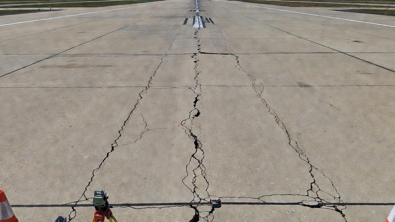
Longitudinal Cracking
Longitudinal cracking that follows the direction of traffic and coincides with settlement zones is a primary visual indicator of differential settlement. The FHWA Long-Term Pavement Performance (LTPP) program classifies longitudinal crack severity based on crack width: Low (less than 3 mm), Moderate (3 to 13 mm), and High (13 mm or greater, with spalling or faulting). Settlement-related longitudinal cracks differ from fatigue-related longitudinal cracks in their pattern — settlement cracks are typically wider, occur near joints or pavement edges where subgrade variability is highest, and are often accompanied by vertical displacement (faulting) on one side of the crack.
Joint Faulting in Concrete Pavements
Faulting is the vertical offset (step) between adjacent concrete slabs at a transverse joint. It is one of the most reliable visual indicators of differential subgrade support conditions. For airport runways, FAA AC 150/5380-6C defines faulting severity as Low (less than 6 mm vertical offset), Moderate (6 to 13 mm), and High (greater than 13 mm). For aprons and taxiways, which experience slower traffic, the thresholds are slightly relaxed: Low (less than 13 mm), Moderate (13 to 25 mm), and High (greater than 25 mm). Faulting occurs when one slab settles more than its neighbor due to differential subgrade compression, pumping of fines from beneath the slab, or loss of load transfer at the joint.
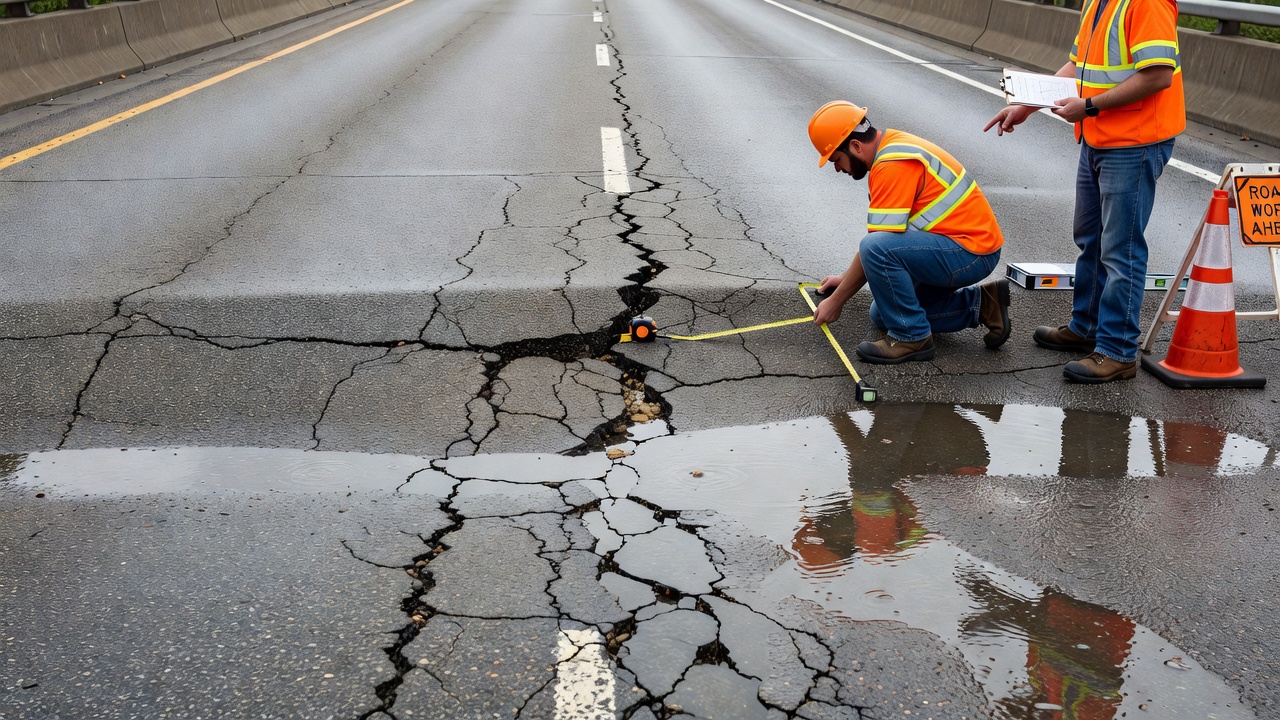
Ponding and Surface Drainage Disruption
Ponding — the collection of water on the pavement surface after rainfall — is perhaps the most immediately observable indicator of differential settlement. Water naturally flows to low points, and a pavement surface that was constructed with proper cross-slope (typically 1.5-2.0% for asphalt pavements, 1.0-1.5% for concrete) will develop localized depressions that trap water. Ponding severity is classified as Low (water film depth less than 6 mm and quick dissipation), Moderate (6 to 25 mm depth, water persists for minutes after rain), and High (greater than 25 mm depth, standing water persists for extended periods). FAA guidance specifies that ponding on airfield pavements persisting more than 30 minutes after rainfall cessation requires investigation.
Ponding is self-accelerating — standing water infiltrates through cracks and joints, softens the subgrade, accelerates pumping and erosion, and causes further settlement that deepens the depression.
Stepped Cracks and Structural Tilt
In structures adjacent to pavements (retaining walls, bridge abutments, buildings), differential settlement manifests as stepped cracks in masonry or concrete walls and measurable tilt in vertical elements. The angular distortion (δ/L) of structural elements provides the quantitative threshold for damage assessment. For mechanically stabilized earth (MSE) walls, angular distortion limits are 1/100; for concrete cantilever retaining walls, 1/200; for bridge abutments on spread footings, 1/200 to 1/300; and for abutments on deep foundations (piles), 1/300 to 1/500. Crack width provides a secondary severity classification: hairline cracks under 1 mm are typically cosmetic, cracks 1 to 5 mm indicate moderate distress requiring investigation, and cracks greater than 5 mm indicate structural significance requiring professional engineering assessment.
Bridge Approach Settlement
Differential settlement at bridge approaches — commonly termed the bump at the end of the bridge — affects approximately 25% of the 600,000+ highway bridges in the United States and costs over $100 million annually in repairs. The settlement occurs predominantly within the first 6 to 12 meters from the abutment face, with approximately 80% of the total settlement occurring in the first 6 m. The Texas DOT classifies approach settlement severity on a 0 to 2 scale, and vertical accelerations exceeding 5.0 m/s² on the approach pavement are considered unacceptable for vehicle occupant safety and bridge preservation.
Differential Settlement in Airport Pavements
Airport pavements are subject to the most stringent surface tolerance requirements of any pavement type because of the critical relationship between surface evenness and aircraft safety. ICAO Annex 14 — Aerodromes requires that runway, taxiway, and apron surfaces be maintained in a condition that prevents FOD generation and ensures safe aircraft ground handling. While ICAO does not prescribe explicit numerical settlement tolerances, it defers to State-specific practices implemented by authorities such as the FAA in the United States.
The FAA Advisory Circular AC 150/5380-6C — Guidelines and Procedures for Maintenance of Airport Pavements provides specific guidance on settlement evaluation. Pavement surface deviations exceeding 6 mm under a 4.5 m straightedge trigger investigation. The FAA Pavement Condition Index (PCI) methodology (ASTM D5340) classifies settlement-related distress severity across multiple defect types including settlement, faulting, and depressions.
FAA AC 150/5320-6G — Airport Pavement Design and Evaluation addresses settlement indirectly through several design provisions. Subgrade compaction requirements specify 95-100% of Modified Proctor density (ASTM D1557) for pavement subgrade and base layers. Expansive soil treatment requires either removal and replacement, chemical stabilization (lime or cement), or moisture control through drainage and vapor barriers. The Cumulative Damage Factor (CDF) approach in the FAARFIELD design software uses mechanistic-empirical methods to limit fatigue damage from traffic loading, indirectly controlling settlement-related pavement deterioration.
For airport pavements, the severity classification of faulting per PCI methodology is stricter than for highways. Runway faulting exceeding 13 mm is classified as High severity and requires immediate repair because of FOD generation potential and aircraft dynamic response concerns. Taxiway and apron faulting tolerances are slightly more relaxed, reflecting lower operating speeds, but still substantially tighter than typical highway standards.
Measurement of Differential Settlement
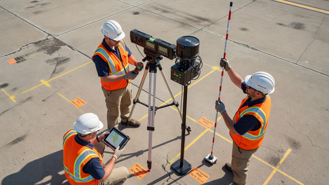
Precise Level Survey
First-Order, Class I level surveys remain the gold standard for vertical settlement measurement, achieving an accuracy of ±0.3√K mm where K is the distance in kilometers. This method uses an optical or digital automatic level and a calibrated rod with invar strip graduations. The survey establishes a network of benchmarks on stable deep foundations (typically driven piles or bedrock piers) and measures settlement points on the pavement surface relative to these fixed references. Repeated surveys at regular intervals produce settlement-versus-time curves that reveal the rate and magnitude of differential movement.
The ASTM E1364 — Standard Test Method for Measuring Road Roughness by Static Level Method provides two accuracy classes for pavement profile measurement: Class 1 (profile error less than 2% of IRI) and Class 2 (profile error less than 5% of IRI). For forensic settlement investigation, the static level method provides the highest vertical accuracy of any field measurement technique.
LiDAR Scanning
Terrestrial LiDAR (Light Detection and Ranging) uses laser pulses to create high-density point clouds of pavement surfaces with typical accuracy of ±2 to 6 mm vertical resolution at ranges up to 100 m. The scanner emits up to 1 million laser pulses per second and records the time-of-flight return to calculate three-dimensional coordinates for each point. The resulting point cloud, containing millions of coordinate measurements per scan station, is processed to create a Digital Elevation Model (DEM) of the pavement surface.
Change detection between sequential LiDAR surveys at intervals of months or years reveals settlement rates as low as 1-5 mm per year. Color-coded deviation maps display the spatial distribution of settlement across the pavement, directly identifying zones of maximum differential movement. For airport pavements, mobile LiDAR systems mounted on vehicles can survey entire runways at traffic speeds, scanning up to 2 million points per second.
Differential GPS and RTK GNSS
Real-Time Kinematic (RTK) GPS provides vertical accuracy of ±2 to 5 cm with a base station and rover configuration. The base station transmits correction data to the rover, eliminating atmospheric and satellite orbit errors through differential correction. While less accurate than optical leveling or LiDAR, RTK GPS offers significant advantages in speed and coverage area. A single surveyor can collect hundreds of settlement readings per hour across an entire airfield pavement network. For higher accuracy requirements, network RTK services using multiple reference stations achieve vertical accuracies approaching ±1-2 cm.
Inertial Profilers and Profilographs
Inertial profilers measure pavement longitudinal profile at traffic speeds using accelerometers and laser sensors to measure the vertical displacement of the vehicle body relative to the pavement surface. The output is the International Roughness Index (IRI), expressed in m/km or in/mile. Differential settlement produces characteristic IRI signatures — localized spikes in the roughness profile that correspond to settlement zones at joints, transitions, and approach slabs.
The profilograph provides a graphical record of pavement surface profile using a multi-wheeled device that mechanically traces the pavement surface. The Profile Index (PI) is calculated as the cumulative deviation from a reference line per unit distance, typically expressed in mm/km or in/mile. Profilographs are widely used for construction quality control and settlement acceptance criteria.
Drone-Based Photogrammetry
Unmanned Aerial Vehicle (UAV) photogrammetry, using structure-from-motion algorithms to process overlapping photographs into three-dimensional models, can achieve vertical accuracies of ±2 to 5 cm when Ground Control Points (GCPs) are used. Drones can survey entire airport pavement networks in a single flight, collecting thousands of overlapping images that are processed into dense point clouds and orthorectified mosaic maps. For settlement detection, repeated drone surveys at intervals of 6-12 months reveal progressive deformation patterns across large pavement areas at substantially lower cost than terrestrial surveys.
The advantage of drone-based inspection for differential settlement detection lies in its ability to cover large areas quickly while providing dense spatial coverage. A 3,000 m runway can be surveyed in a single 20-minute flight, producing a point cloud with millions of measurements that capture settlement patterns across the entire pavement surface.
Detection of Differential Settlement by Drone Survey
Drone-based detection of differential settlement leverages photogrammetric Structure-from-Motion (SfM) and aerial LiDAR technologies to produce high-resolution Digital Surface Models (DSMs) of pavement infrastructure. The workflow begins with mission planning — establishing flight parameters including altitude (typically 50-120 m above ground level), forward and side overlap (70-80% for photogrammetry), and ground sampling distance (GSD). Lower flight altitudes produce higher resolution models but require longer flight times.
Ground Control Points (GCPs) are placed at surveyed locations across the pavement surface and used to georeference the photogrammetric model to absolute coordinates. For settlement detection, at least 5 GCPs per hectare with RTK GPS coordinates provide the necessary geodetic control. The GCPs establish the reference frame against which future surveys are compared.
The drone collects overlapping images that are processed using computer vision algorithms to identify common features across multiple images. From these matching features, the software computes the camera positions and generates a sparse point cloud. Multi-view stereo (MVS) reconstruction then densifies this into a high-resolution point cloud containing tens of millions of points. The point cloud is georeferenced using the GCPs and filtered to remove vegetation and non-pavement features.
The resulting DSM is compared to the as-designed pavement surface or to previous survey datasets. Change detection algorithms compute the vertical deviation at each point, producing color-coded deviation maps that directly reveal settlement patterns. Zones of differential settlement appear as localized depressions with characteristic shape and orientation relative to pavement joints, edges, and transitions.
Drone survey for settlement detection offers several advantages over traditional methods. Coverage — a single flight covers hundreds of hectares that would require days of terrestrial survey. Spatial density — millions of measurements versus hundreds for manual survey, revealing settlement patterns that point measurements would miss. Archival — the digital model serves as a permanent record that can be compared to future surveys. Integration — settlement data can be combined with crack detection, surface condition mapping, and FOD analysis within a single inspection platform. The limitation is vertical accuracy, which at ±2-5 cm with GCPs is lower than precise optical leveling but generally sufficient for identifying settlement zones requiring further investigation.
Repair Methods for Differential Settlement
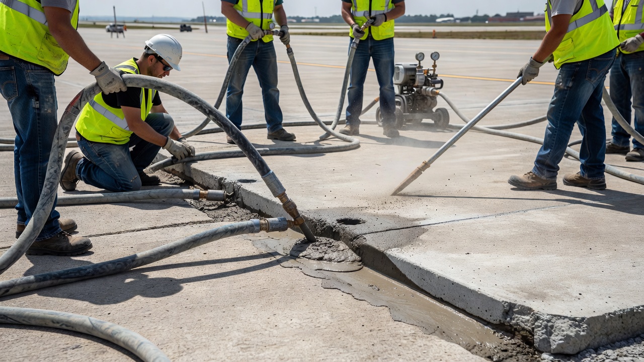
Mudjacking (Slab Jacking)
Mudjacking is the injection of a cement-sand-water slurry beneath settled concrete pavement slabs at pressures of 150 to 400 psi to lift them back to grade. The process involves drilling 40-50 mm diameter holes through the slab at planned locations, injecting the grout mixture through these holes using a positive-displacement pump, and monitoring lift using dial gauges or laser levels placed at survey points on the surface. The grout fills voids beneath the slab, compresses loose subgrade soils, and hydraulically lifts the slab as the injection pressure overcomes the slab self-weight.
The typical grout mixture consists of 1 part Portland cement to 2-4 parts sand by volume, with sufficient water to produce a pumpable slurry with a slump of 150-200 mm. The slurry density ranges from 1,800 to 2,200 kg/m³, and compressive strength after curing reaches 3-7 MPa at 28 days. Mudjacking costs range from $3 to $8 per square foot and requires 24-48 hours of curing time before traffic reopening. The primary limitation is that the grout adds weight to the pavement system, which may accelerate further settlement if the underlying subgrade has not been adequately stabilized. Additionally, mudjacking is effective only for slabs that are structurally intact — severely cracked slabs require replacement rather than lifting.
Polyurethane Foam Injection
Polyurethane foam jacking uses high-density closed-cell foam injected through pea-sized (10-15 mm) holes in the pavement. The foam consists of two liquid components — isocyanate and polyol resin — that react when mixed at the injection point, expanding to 20-30 times their liquid volume within seconds and curing to full strength within 15 minutes. The final foam density ranges from 40 to 60 lb/ft³ (640-960 kg/m³), and the closed-cell structure prevents water infiltration.
Polyurethane jacking offers several advantages over mudjacking: cure time of 15 minutes versus 24-48 hours for mudjacking, enabling same-day traffic reopening; lightweight — the foam adds minimal dead load to the subgrade, reducing the risk of further settlement; precise lift control — the expanding foam provides centimeter-level lift control; and waterproofing — the closed-cell foam seals the subgrade against moisture infiltration. Cost ranges from $9 to $14 per square foot with a service life of 10-20 years.
Slab Replacement
When concrete slabs are severely cracked, faulted, or the underlying subgrade has experienced significant consolidation, full-depth slab replacement is the definitive repair. The deteriorated slab is saw-cut to a clean rectangular shape, broken and removed with a hydraulic breaker, and the subgrade is recompacted or stabilized before placing new concrete.
The procedure requires dowel bar retrofitting at transverse joints to restore load transfer. Dowel bars of 32-38 mm diameter, 450 mm long are installed into drilled holes at mid-depth of the slab, grouted with epoxy or non-shrink grout, and aligned parallel to the pavement surface and centerline. Joints are sealed with silicone sealant (ASTM C920) to prevent moisture infiltration. Slab replacement costs range from $8 to $20 per square foot and provides a 15-25 year service life depending on traffic loading and subgrade conditions. Curing time of 7-14 days before traffic reopening is a significant operational constraint for airport applications.
Subgrade Stabilization
Subgrade stabilization alters the engineering properties of the soil to increase strength, reduce compressibility, and control volume change. Lime stabilization (3-8% by dry weight of soil) is effective for plastic clay soils. Lime reacts with clay minerals through cation exchange, flocculation, and pozzolanic reactions to reduce plasticity, increase workability, and develop long-term strength gains. Cement stabilization (5-10% by weight) is suitable for granular and low-plasticity soils, producing rapid strength gain through hydration reactions that bind soil particles together. Fly ash (10-30% by weight) provides pozzolanic reactions for soil stabilization at lower cost than cement, with typical unconfined compressive strengths of 300-800 psi at 28 days.
Stabilization is applied by spreading the stabilizer on the prepared subgrade surface, dry mixing to the specified depth (typically 150-300 mm), adding water to bring the mixture to optimum moisture content, compacting to specified density, and curing before pavement placement.
Deep Soil Improvement
For deep soft soil deposits that cannot be treated by surface stabilization, deep mixing methods provide effective ground improvement. Deep Soil Mixing (DSM) uses large-diameter auger mixing tools (2-8 ft diameter) that penetrate to depths of 20-150 ft, blending cement or lime slurry with the in-situ soil to create treated soil columns with strengths 5-12 times the untreated soil strength. Stone columns (also called vibro-replacement columns) are constructed by introducing dense aggregate into the ground using a vibrating probe, creating columns that reinforce the soil mass, accelerate consolidation, and increase bearing capacity by 2-4 times while reducing total settlement by 40-70%.
Compaction Grouting
Compaction grouting involves injecting stiff, low-slump grout (typically less than 25 mm slump) under high pressure into loose soils or voided zones. The grout forms growing bulbs that densify the surrounding soil through displacement rather than permeation. Injection pressures range from 200 to 600 psi at the pump, with the grout bulb expanding until it encounters sufficient confining resistance from the densified soil. Compaction grouting is effective for treating loose fills, natural voids, and zones of undermining beneath existing pavements without requiring excavation.
Prevention of Differential Settlement
Preventing differential settlement begins during geotechnical site investigation. A thorough subsurface exploration program using soil borings, test pits, and in-situ testing (Standard Penetration Test, Cone Penetration Test, and pressuremeter testing) identifies zones of variable soil conditions, soft compressible layers, and potential problematic soils. The investigation must be sufficiently dense to capture the variability across the pavement footprint — a single boring at each end of a runway is inadequate to characterize a complex subsurface profile.
Subgrade preparation during construction is the primary line of defense. Specifications typically require the following minimum compaction standards: 95% of Modified Proctor maximum dry density (ASTM D1557) for base and subbase layers, 95% for the top 150 mm of subgrade beneath pavements, and 90-92% for subgrade fill below 150 mm depth. Moisture content must be maintained within ±2% of optimum moisture content during compaction. Verification testing at the frequency of 1 density test per 2,000-5,000 ft² per lift provides quality control documentation.
Drainage design is critical to long-term prevention of differential settlement. Surface drainage provides cross-slope of 1.5-2.0% for asphalt and 1.0-1.5% for concrete to rapidly remove precipitation. Subsurface drainage using edge drains, underdrains, and daylighting provides removal of groundwater and infiltrated water before it can saturate the subgrade. Open-graded base layers with permeability greater than 10⁻² cm/s allow rapid drainage of water trapped within the pavement structure. The AASHTO drainage coefficient (Cd) rates drainage quality from Excellent (time to drain 50% of saturation = 2 hours) to Poor (time to drain > 1 month) and adjusts structural layer coefficients accordingly.
Expansive soil mitigation includes removal and replacement of highly expansive soils (EI greater than 90) to a depth of at least 600-900 mm, chemical stabilization with lime (3-8% by weight), moisture barriers (geosynthetic vapor barriers extending beyond pavement edges), and proper drainage to prevent moisture migration beneath the pavement.
Transition zone design at the interface between cut and fill sections, between flexible and rigid pavement types, and at bridge approaches requires careful geotechnical detailing. Approach slabs at bridges are designed to span the settlement-prone zone immediately behind the abutment, transitioning the vertical grade change from a localized fault to a gradual slope. Geosynthetic reinforcement (geogrids) placed at the base of fills and approach embankments distributes loads and reduces differential movement.
Construction monitoring and quality assurance with proof-rolling of the prepared subgrade, plate bearing tests (ASTM D1195/D1196) to verify subgrade modulus, and falling weight deflectometer (FWD) testing of completed pavement sections provide verification that the constructed pavement will perform as designed.
Long-term monitoring using settlement plates, inclinometers, and periodic precision level surveys or drone-based photogrammetry identifies developing differential settlement before it reaches critical thresholds, enabling proactive maintenance that prevents major structural damage. The recommended monitoring frequency for critical structures is quarterly during the first year after construction (when settlement rates are highest), semi-annually during years 2-3, and annually thereafter until settlement rates stabilize below 1 mm per year.
Frequently Asked Questions
Uniform settlement lowers the entire pavement or structure by the same amount without introducing distortion, angular rotation, or cracking. For example, a building settling 25 mm evenly across its foundation will not experience structural distress. Differential settlement, by contrast, produces relative vertical displacement between adjacent points, creating angular distortion (δ/L), tensile cracking, joint faulting, and serviceability problems. Allowable differential settlement limits are typically more restrictive than total settlement limits in geotechnical codes.
The most common causes are variable subgrade conditions (lateral changes in soil type or stiffness), poor compaction during construction (below 95% of Modified Proctor density), expansive clay soils undergoing cyclic shrink-swell, moisture infiltration weakening subgrade support, undermining from leaking utilities or internal erosion, frost heave and thaw weakening, and consolidation of soft soils under fill embankments. Airport pavements are particularly sensitive because of heavy aircraft loads and strict surface tolerance requirements.
Differential settlement is measured using precise level surveys (First-Order, Class I accuracy of ±0.3√K mm), terrestrial and aerial LiDAR scanning (2-6 mm vertical accuracy), RTK GPS survey (2-5 cm vertical accuracy), inertial profilers for IRI measurement, and profilographs for longitudinal profile deviation. For airport pavements, FAA AC 150/5380-6C specifies investigation when deviations exceed 6 mm under a 4.5 m straightedge. Drone-based photogrammetry with Ground Control Points can achieve 2-5 cm accuracy over large pavement areas.
Key visual indicators include longitudinal cracking along pavement joints or mid-slab, transverse cracking at irregular intervals, faulting (vertical step-off) at transverse joints typically measured in millimeters, ponding of water where surface depressions collect rainfall, stepped cracks in adjacent structures, tilting of retaining walls or bridge abutments, and a rough riding surface. At bridge approaches, the bump at the end of the bridge is a classic settlement indicator occurring within approximately 6 m of the abutment.
Repair methods include mudjacking (cement-sand slurry injected at 150-400 psi to lift slabs), polyurethane foam injection (15-minute cure time, closed-cell waterproof foam), slab replacement with full-depth saw-cutting and dowel bar retrofitting, subgrade stabilization using lime (3-8% for clay soils) or cement (5-10% for granular soils), deep soil mixing, stone columns for soft soil improvement, compaction grouting to densify loose fills, and drainage improvements such as edge drains and open-graded base layers to prevent moisture-related settlement.
ICAO Annex 14 does not prescribe explicit numerical settlement tolerances but requires that pavement surfaces be maintained to prevent FOD and ensure safe aircraft operations. FAA AC 150/5380-6C specifies that pavement surface deviations exceeding 6 mm under a 4.5 m straightedge warrant investigation. FAA AC 150/5320-6G addresses settlement indirectly through subgrade compaction requirements (95-100% of Modified Proctor density), treatment of swelling soils, and the use of the Cumulative Damage Factor (CDF) in mechanistic-empirical pavement design. For concrete joint faulting, runway tolerances are Low (< 6 mm), Moderate (6-13 mm), and High (> 13 mm).
Differential settlement at bridge approaches, commonly known as the bump at the end of the bridge, affects approximately 25% of highway bridges in the United States and costs over $100 million annually in repairs. Settlement occurs from consolidation of approach embankment fill, compression of natural subgrade beneath the fill, and abutment rotation. Approximately 80% of the total settlement occurs within the first 6 m from the abutment. The Texas DOT classifies approach settlement severity on a 0-2 scale, and vertical accelerations exceeding 5.0 m/s² on the approach pavement are considered unacceptable for vehicle safety.
Yes. Ground Penetrating Radar (GPR) can detect subsurface voids and loss of subgrade support before surface distress becomes visible. LiDAR change detection from repeated surveys can identify progressive settlement rates of 1-5 mm per year. Inclinometers installed beneath fills measure lateral displacement and settlement profiles at depth. Automated Total Stations (AMTS) provide continuous 24/7 monitoring of settlement points with ±0.5-5.0 mm accuracy. Fiber optic distributed strain sensors embedded in pavement or subgrade can detect strain anomalies correlated with developing settlement zones.
Detect Differential Settlement with Drone Surveys
TarmacView uses AI-powered drone inspection to detect and quantify differential settlement across airport pavements, runways, taxiways, and bridge approaches. Our platform generates precise settlement maps and prioritizes repair zones.
Faulting at Joints and Cracks in Concrete Pavements
Faulting is the vertical displacement at a transverse joint or crack in concrete pavement, creating a 'step' felt by vehicles crossing the joint. It results fro...
D-Cracking (Durability Cracking) in Concrete Pavements
D-cracking is a pattern of closely spaced crescent-shaped cracks near joints, edges, and cracks in PCC pavements, caused by freeze-thaw deterioration of suscept...
Delamination is the separation of concrete layers along a plane approximately parallel to the surface, creating subsurface voids detectable by hammer sounding, ...
37 min read
Concrete Defects
Bridge Inspection
+3
Cookie Consent We use cookies to enhance your browsing experience and analyze our traffic. See our privacy policy.