Tie Bar
Tie bars are deformed steel bars placed across longitudinal joints in concrete pavement to prevent lane separation and hold adjacent slabs tightly together. Unl...
28 min read
Concrete Pavement
Joint Design
+3
Dowel bars are smooth, round steel bars placed across transverse joints in jointed plain concrete pavement (JPCP) to transfer wheel loads between adjacent slabs while allowing horizontal joint movement. Dowel bar condition and load transfer efficiency are critical inspection items for airport PCC runways. Covers design, placement, corrosion, misalignment, and retrofit using dowel bar retrofit (DBR).
A dowel bar is a smooth, cylindrical steel rod placed transversely across a joint in jointed plain concrete pavement (JPCP) to provide mechanical load transfer between adjacent concrete slabs. The dowel bar’s primary function is to transfer vertical wheel loads from the loaded slab to the neighboring unloaded slab as an aircraft or vehicle crosses the joint, thereby reducing the vertical deflection and tensile bending stress at the slab edge. This load transfer mechanism directly mitigates the development of faulting — the differential vertical displacement between slabs that creates a step at the joint and degrades ride quality and safety.
Unlike deformed reinforcing bars (rebar) that bond to concrete along their entire length, dowel bars are deliberately smooth and round, with at least one half of the bar debonded from the concrete through the application of a bond-breaking compound, grease, or a plastic sleeve. This debonding detail is fundamentally important: the dowel must resist vertical shear forces to transfer loads, but it must also allow the joint to open and close horizontally as the concrete slabs expand and contract with diurnal and seasonal temperature changes. A dowel that is bonded on both sides of the joint restrains this horizontal movement, generating tensile stresses that can crack the slab.
At airports, dowel bars are installed in transverse contraction joints (sawn or formed joints that control the location of shrinkage cracking) and transverse construction joints (joints between adjacent paving placements such as at the end of a day’s production). The FAA requires dowels in all transverse construction joints and in transverse contraction joints for pavements serving aircraft heavier than 100,000 lb (45,360 kg) when the pavement is not designed to rely solely on aggregate interlock for load transfer. Properly functioning dowel bars are the single most important mechanical element determining the long-term structural performance of airport concrete pavements.
The physics of dowel action involves a complex interaction of bearing stress between the steel bar and the surrounding concrete, shear stress within the bar itself, and bending of the bar under load. When an aircraft wheel load approaches the joint on one slab, the vertical deflection of that slab engages the embedded half of the dowel. The dowel then transfers a portion of that load — typically between 30 and 50 percent depending on joint stiffness, slab thickness, subgrade support, and dowel characteristics — into the adjacent slab. The dowel bar essentially bridges the joint, distributing the applied load across two slabs instead of one. This load-sharing reduces the peak tensile stress at the bottom of the loaded slab by 25 to 40 percent compared to an undoweled joint, significantly extending fatigue life. The theoretical basis for dowel load transfer was established by Westergaard’s early analytical work on concrete pavement stresses, later refined by Timoshenko and Lessels who developed the beam-on-elastic-foundation model that remains the analytical backbone of modern dowel design. Contemporary finite element models, such as those implemented in FAARFIELD and the FAA’s three-dimensional finite element analysis framework, account for the nonlinear concrete-dowel interaction including the formation of a slight gap around the dowel due to repeated loading and concrete consolidation.
Dowel bar dimensions are not arbitrary; they are prescribed by regulatory agencies based on decades of full-scale testing and field performance data. The FAA AC 150/5320-6G (Airport Pavement Design and Evaluation) provides explicit dimensional requirements in Table 3-6, which ties dowel diameter and spacing to the thickness of the concrete slab. This relationship reflects the fundamental engineering principle that thicker slabs distribute loads over a wider area, reducing the shear demand on individual dowels but also requiring proportionally larger dowels to maintain stiffness compatibility between the slab and the joint.
The complete FAA dowel dimensions table is reproduced below, incorporating the values from FAA AC 150/5320-6G and earlier editions (6E, 6F) that remain consistent in their core recommendations:
| Slab Thickness | Dowel Diameter | Dowel Length | Dowel Spacing (center-to-center) |
|---|---|---|---|
| 6–7 in (152–178 mm) | 3/4 in (20 mm) | 18 in (457 mm) | 12 in (305 mm) |
| 7.5–12 in (191–305 mm) | 1 in (25 mm) | 19 in (483 mm) | 12 in (305 mm) |
| 12.5 in and greater (>318 mm) | 1-1/4 in (32 mm) | 20 in (508 mm) | 12 in (305 mm) |
The standard 12-inch (305 mm) center-to-center spacing places dowels at regular intervals across the full width of the paving lane, ensuring that every aircraft wheel path crossing the joint encounters at least two or three active dowels. For a typical 25-foot (7.6 m) wide runway paving lane, this translates to approximately 24 to 25 dowels per transverse joint. The number of dowels per wheel path is critical: research by the Iowa State University National Concrete Pavement Technology Center shows that at least two dowels must be engaged per wheel load to prevent excessive bearing stress concentrations that can crush the surrounding concrete and initiate joint deterioration.
Dowel length is set to provide sufficient embedment on each side of the joint. Half the total length is embedded in each slab, so an 18-inch (457 mm) dowel provides 9 inches (229 mm) of embedment per slab. This embedment depth must exceed the minimum required to develop the dowel’s shear capacity without concrete bearing failure. The American Concrete Pavement Association (ACPA) recommends a minimum embedment length of eight times the dowel diameter on each side of the joint. For a 1-inch (25 mm) diameter dowel with 9 inches of embedment, the embedment ratio is 9:1, comfortably exceeding the minimum 8:1 ratio.
Dowel coatings serve two distinct purposes: bond-breaking and corrosion protection. The portion of the dowel on one side of the joint — typically one-half of its length — must be treated with a bond-breaking compound to prevent adhesion between the steel and the surrounding concrete, ensuring free horizontal movement. This bond-breaker is commonly a thin layer of form-release oil, paraffin wax, or a factory-applied epoxy debonding coating. Some specifications call for a plastic sleeve that encases one end of the dowel, creating both a bond-break and a small void space at the bar end to accommodate the slight longitudinal translation that occurs as joints permanently open over time.
Corrosion protection of dowel bars has evolved significantly over the past two decades. Historically, bare carbon steel dowels were common but proved vulnerable to corrosion in the presence of moisture and deicing chemicals penetrating through unsealed or poorly sealed joints. The University of California Pavement Research Center (UCPRC) conducted an extensive laboratory corrosion study (UCPRC-RR-2005-10) comparing bare carbon steel, flexible epoxy-coated steel (green), non-flexible epoxy-coated steel (purple and gray), stainless steel clad, grout-filled hollow stainless steel, and microcomposite steel (MMFX 2). The study’s findings were definitive: bare carbon steel dowels should not be used in any environment where chlorides are present. Epoxy-coated carbon steel dowels provide adequate protection but are susceptible to coating damage during shipping, handling, and placement — every examined epoxy-coated bar exhibited one or more coating holidays (defects), particularly along the cut ends and edges. The study recommended strict quality control for holiday detection and mandatory epoxy coating of bar ends.
For high-risk environments such as mountain passes subject to heavy deicer application and marine coastal airports with airborne chloride exposure, the research recommended upgrading to stainless steel clad, hollow stainless steel, or microcomposite steel dowels. The Wisconsin DOT conducted a parallel five-year field evaluation comparing MMFX 2 microcomposite steel dowels against conventional epoxy-coated dowels in 9-inch JPCP and found that both dowel types performed comparably in terms of LTE retention, with the MMFX 2 dowels exhibiting no measurable corrosion after five years in a harsh freeze-thaw environment with regular deicing salt application. The unit cost premium for corrosion-resistant dowels — typically 30 to 100 percent over epoxy-coated carbon steel — must be weighed against the lifecycle cost of premature joint failure, DBR rehabilitation, or full-depth slab replacement triggered by corroded dowels locking joints.
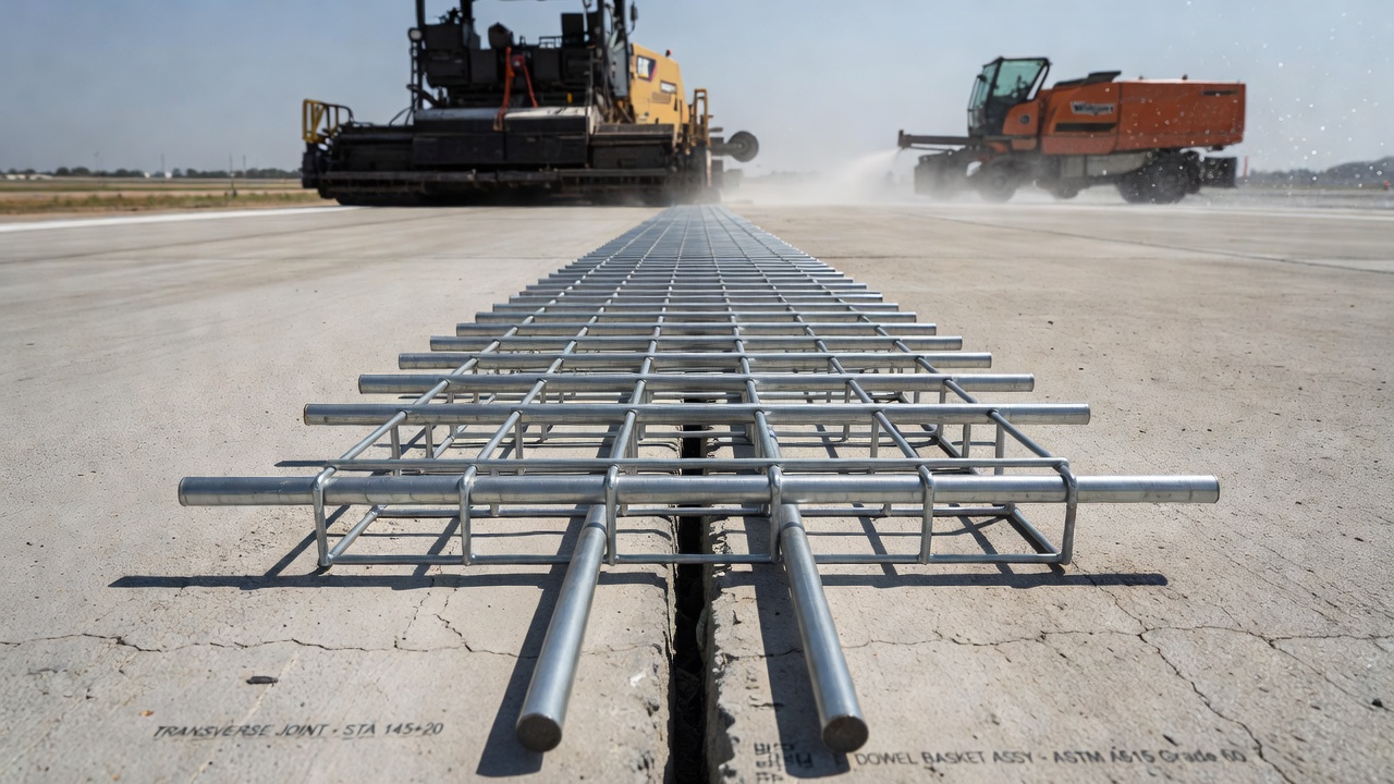
The placement accuracy of dowel bars during construction directly determines whether the joint will perform as intended or become a source of premature distress. Dowel bars can be placed using two methods: pre-placed dowel basket assemblies secured to the subbase or base course prior to concrete paving, or dowel bar inserters (DBI) mounted on the slipform paver that vibrate dowels into the fresh concrete behind the paving machine. Each method carries distinct alignment risks and quality control requirements.
Pre-placed dowel baskets consist of steel wire frames — typically fabricated from No. 4 or No. 5 deformed reinforcing bars — that hold individual dowels at the specified height, spacing, and alignment. The basket assembly is staked or nailed to the base course before concrete placement. The basket must be rigid enough to resist displacement during concrete placement and consolidation. FAA specifications require that dowels be positioned at mid-depth of the slab, within a tolerance of ±1/4 inch (6 mm) vertically. The horizontal alignment tolerance is typically ±1/4 inch per foot of dowel length (20 mm/m), meaning a 20-inch dowel may not deviate more than approximately 0.4 inches (10 mm) from true perpendicular to the joint over its entire length. The pre-placed method generally achieves superior alignment accuracy compared to the inserter method but requires additional labor and time during construction, as paving operations must proceed carefully around the fixed baskets.
Dowel bar inserters automate the placement process, inserting individual dowels or groups of dowels into the freshly placed concrete behind the paver’s slipform pan. This method is faster and eliminates the need for baskets, but it introduces alignment variability because the dowel is pushed through plastic concrete that offers resistance to penetration. The Nebraska Department of Transportation conducted an extensive evaluation of dowel bar inserter practices (NDOR Research Project M036) using MIT Scan-2 magnetic imaging tomography to measure the alignment of over 2,300 joints constructed with DBIs. The study found that longitudinal translation — the deviation of the dowel’s center point from the joint line — was the most common form of misalignment, with most dowels falling within a range of ±2 inches (51 mm) of the joint. While the majority of dowels met specification tolerances, the study identified a meaningful correlation between inserter maintenance and calibration frequency and alignment quality, recommending that DBIs be recalibrated after every 1,500 to 3,000 linear feet (450–900 m) of paving.
Dowel embedment refers to the depth of concrete cover above and below the bar. Standard practice places dowels at the slab mid-depth, which for a 12-inch (305 mm) slab means the dowel centerline is 6 inches (152 mm) from both the top and bottom surfaces. In thicker slabs exceeding 14 inches (356 mm), some agencies position dowels slightly above mid-depth — typically at 40 percent of slab thickness from the top — to better resist the higher bending stresses that occur near the top of the slab under aircraft wheel loads. Embedment below the dowel is equally important; insufficient concrete cover below the dowel increases the risk of bearing stress failure at the dowel-concrete interface and can lead to the formation of a vertical crack propagating downward from the dowel.
Dowel lubrication or bond-breaking treatment is mandatory on at least one end of every dowel to ensure the joint can open and close freely. A non-degrading bond-breaker such as a factory-applied debonding coating, a heavy coating of form-release oil, or a 0.030-inch (0.76 mm) thick plastic sleeve covering 7 to 8 inches (178–203 mm) of one half of the bar is industry standard. Sleeves must include an end cap or compressible foam insert at the bar tip to create a small expansion pocket. Without this pocket, the translating bar end would bear against the concrete at the end of the sleeve, generating a point load and potentially spalling the concrete. The unbonded length must be sufficient to accommodate the anticipated joint opening, which for a 20-foot (6.1 m) slab spacing in a climate experiencing a 100°F (56°C) annual temperature range can be as much as 0.15 inches (3.8 mm) per joint. The coefficient of thermal expansion of concrete is approximately 5.5 × 10⁻⁶ per °F, so a 20-foot slab subjected to a 100°F temperature drop contracts by about 0.13 inches (3.3 mm), confirming the need for an effective bond-breaker over the full expected range of movement.
Load Transfer Efficiency (LTE) is the quantitative measure of a joint’s ability to transfer load from one slab to the adjacent slab. It is expressed as a percentage and is defined in FAA AC 150/5320-6G as the ratio of the deflection of the unloaded slab to the deflection of the loaded slab at the joint, measured under a known applied load. The standard deflection-based formulation (LTEδ) is:
LTEδ = (δu / δl) × 100%
where δu is the maximum vertical deflection measured on the unloaded (leave) slab and δl is the maximum vertical deflection measured on the loaded (approach) slab at the joint, both under the same applied impulse load. A joint with perfect load transfer would theoretically exhibit identical deflections on both slabs (LTE = 100%), while a joint with zero load transfer — such as a fully opened crack with no aggregate interlock and no dowels — would exhibit zero deflection on the unloaded slab (LTE = 0%).
FAA guidance indicates that LTE values of 70 to 75 percent or higher are generally acceptable for airport rigid pavements. Values below 60 percent typically trigger consideration of rehabilitation, particularly if accompanied by measurable faulting or corner cracking. The threshold is not absolute; it depends on aircraft loading severity, traffic volume, and the presence of other distresses. A joint with LTE of 65 percent may be acceptable on a lightly trafficked general aviation taxiway but unacceptable on a primary runway serving wide-body aircraft.
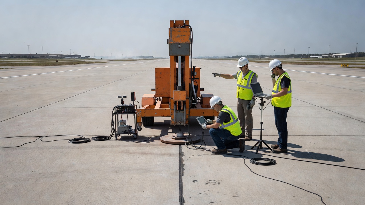
The primary tool for measuring LTE in the field is the Falling Weight Deflectometer (FWD) or its heavy-load counterpart, the Heavy Weight Deflectometer (HWD). The FWD/HWD operates by dropping a mass onto a loading plate — typically 12 inches (300 mm) in diameter for airport testing — producing an impulse load that simulates a moving aircraft wheel. The standard test configuration specified in ASTM D4694 positions the loading plate on one side of the joint with the plate edge tangent to the joint line. Multiple deflection sensors (typically seven to nine geophones) are arranged in a linear array, with the first sensor centered on the loading plate and the remaining sensors extending onto the unloaded slab. The key measurement points are the sensor directly under the load (δl) and the first sensor on the far side of the joint, typically 12 inches (300 mm) from the load center (δu).
FAA AC 150/5320-6G, Appendix C provides detailed procedures for nondestructive testing (NDT) using FWD-type devices. The appendix specifies a three-tier load level typically corresponding to 12,000, 24,000, and 36,000 lb (53, 107, and 160 kN) for airport pavements. Testing at multiple load levels is important because LTE can be load-dependent — joints with degraded aggregate interlock often show lower LTE at higher loads as interlock mechanisms are overcome. The FAA also recommends testing under temperature conditions representative of the critical season, since LTE varies with joint opening width: narrow joints in hot weather produce higher aggregate interlock contributions (potentially inflating LTE), while wide joints in cold weather reduce interlock and reveal the true contribution of the dowel bars.
Stress-based LTE (LTEσ) is an alternative metric that measures load transfer efficiency in terms of tensile stress reduction rather than deflection transfer. LTEσ is computed by comparing the maximum tensile stress at the bottom of the loaded slab in the doweled joint configuration to the stress in an undoweled configuration. Research at Rowan University comparing stress-based and deflection-based LTE for airfield rigid pavements demonstrated that LTEσ is consistently lower than LTEδ — meaning deflection-based measurements overstate the structural benefit of load transfer. Under moving aircraft gear loads, typical LTEσ values for properly doweled joints range from 35 to 55 percent, compared to LTEδ values of 75 to 90 percent for the same joints. The practical implication is that pavement designers should not assume that a joint with 80 percent deflection-based LTE is transferring 80 percent of the stress; the actual stress reduction is more modest.
Dowel bar misalignment occurs when installed dowels deviate from their specified position and orientation relative to the joint. Misalignment is categorized into four primary types:
Horizontal skew — the dowel is rotated in the horizontal plane, such that it is not perpendicular to the joint line. This is the most detrimental form of misalignment because it directly restrains joint opening and closing. As the slabs contract and the joint widens, a horizontally skewed dowel binds against the concrete on both sides of the joint, generating high tensile stresses parallel to the joint. These restraint stresses can exceed the tensile strength of the concrete, producing transverse cracks that initiate at the dowel location and propagate across the slab. Finite element analysis by the FHWA LTPP program quantified this effect: a horizontal skew of only 1/4 inch over 18 inches (equivalent to an angle of approximately 0.8 degrees) can increase joint restraint stresses by 60 to 80 percent compared to a perfectly aligned dowel.
Vertical tilt — the dowel is angled in the vertical plane, usually with one end higher or lower than the other. Vertical tilt does not restrain horizontal joint movement directly, but it reduces the effective bearing area between the dowel and the surrounding concrete. A vertically tilted dowel concentrates bearing stresses along a narrow contact band rather than distributing them over the full projected diameter, increasing the risk of concrete crushing at the dowel-concrete interface. Additionally, if the vertical tilt is severe enough to place one end of the dowel too close to the slab surface — within 2 inches (51 mm) of the top — the reduced cover can lead to surface spalling or even expose the dowel to direct deicer contact.
Longitudinal translation — the entire dowel is shifted longitudinally such that its center is not aligned with the joint line. This places different embedment lengths on each side of the joint, with the shorter embedment side potentially providing insufficient development length to resist shear. If embedment falls below four dowel diameters on either side, the risk of pullout or concrete cone failure increases significantly.
Vertical translation — the entire dowel is shifted upward or downward from mid-depth. This alters the lever arm for load transfer and can place the dowel in a region of higher or lower concrete confinement. Dowels placed too close to the top or bottom surface may not be adequately confined and can contribute to surface spalling or bottom-initiated cracking.
The FHWA Long-Term Pavement Performance (LTPP) Data Analysis Program report FHWA-HRT-20-070 represents the most comprehensive field investigation of dowel misalignment effects to date. The study used MIT (Magnetic Imaging Tomography) scanning — specifically the MIT Scan-2 device — to nondestructively measure the alignment of dowels at 121 LTPP test sections across the United States. MIT Scan-2 technology works by generating a pulsed magnetic field that induces eddy currents in the steel dowels, with sensors measuring the response to reconstruct the three-dimensional position and orientation of each bar. The analysis found that the majority of dowels in LTPP sections met alignment tolerances, and the study concluded that while dowel misalignment is a contributing factor to joint distress, its effects are generally secondary to other variables such as slab thickness, traffic loading, climate severity, and base type. No definitive statistical relationship was established between the joint score (a composite misalignment index) and the incidence of cracking or spalling across most states.
However, the FHWA study did identify a measurable relationship between dowel misalignment and the rate of long-term LTE loss. Using the equivalent dowel diameter concept — a methodology from NCHRP Report 637 that computes the effective diameter of a perfectly aligned dowel array that would produce the same joint stiffness as the actual misaligned array — the researchers found that incorporating equivalent dowel diameter into AASHTOWare Pavement ME Design models produced less biased predictions of long-term LTE than using nominal dowel diameter. This finding confirms that misalignment degrades load transfer over time, even if the immediate effect on initial LTE is small. For airport pavements, where the consequences of joint failure are severe and repair access is highly constrained, maintaining alignment tolerances of ±1/4 inch vertical and ±1/4 inch per foot horizontal is a prudent construction quality requirement.
Dowel bar corrosion is a progressive failure mechanism that compromises both the structural capacity of the joint and its ability to accommodate horizontal slab movement. The corrosion process in concrete-embedded steel follows a well-established two-stage model: an initiation stage during which aggressive agents — primarily chloride ions from deicing chemicals or carbon dioxide from the atmosphere — penetrate through the joint sealant and along the dowel-concrete interface to depassivate the protective alkaline film on the steel surface, followed by a propagation stage during which active corrosion reduces the steel cross-section and generates expansive corrosion products.
For dowel bars, the initiation stage is inherently shorter than for other reinforced concrete elements because of the direct exposure pathway through the joint opening. Even in well-sealed joints, moisture and dissolved chlorides can reach the dowel through three routes: downward infiltration through the joint sealant system, lateral ingress from the unsealed sides of the pavement lane, and capillary rise from the subbase through the joint bottom. The UCPRC corrosion study quantified this vulnerability by measuring half-cell potentials on dowels embedded in concrete beams with simulated joints. Bare carbon steel dowels exhibited active corrosion potentials (more negative than -350 mV versus a copper-copper sulfate reference electrode, indicating a greater than 90 percent probability of active corrosion) within 30 days of exposure to a 3.5 percent sodium chloride solution.
The accumulation of corrosion products — primarily iron oxides and hydroxides that occupy a volume two to six times greater than the parent steel — creates a particularly damaging condition at doweled joints. As the dowel corrodes within the confined space of its concrete embedment, the expanding rust layer exerts radial pressure on the surrounding concrete. This pressure can initiate longitudinal cracking along the dowel line, which further accelerates chloride ingress and creates a self-reinforcing cycle of deterioration. More critically, the corrosion product buildup on the dowel surface increases the friction between the dowel and concrete, progressively locking the joint against horizontal movement. A joint that can no longer open to relieve thermal contraction stresses will crack at an adjacent location — typically at the next joint or mid-panel — transferring and concentrating the problem.
Epoxy coating is the most widely adopted corrosion protection strategy for dowel bars. Fusion-bonded epoxy coatings applied per ASTM A775 provide a dielectric barrier that electrically isolates the steel from the concrete pore solution. The coating specification requires a minimum thickness of 7 mils (0.18 mm) and a maximum of 12 mils (0.30 mm), with strict limits on the number and size of allowable holidays. However, the UCPRC study found that field-handled epoxy-coated dowels invariably have coating damage, particularly along cut ends (where the bar was sheared to length after coating), along the edges at the bar ends, and at points of contact with the steel dowel basket during assembly and concrete placement. The study’s specific recommendation that bar ends be coated with epoxy and that quality control include holiday detection using a high-voltage pinhole detector (typically 67.5 to 90 V per mil of coating thickness) has been adopted by several state highway agencies for critical pavement applications.
Stainless steel dowels eliminate the corrosion initiation problem by using alloys that resist chloride-induced depassivation. Solid stainless steel bars of Type 316LN or duplex 2205 stainless steel have been used in extreme environments, though their cost — approximately four to eight times that of epoxy-coated carbon steel on a per-bar basis — limits their application. Stainless steel clad dowels, which consist of a carbon steel core metallurgically bonded to a stainless steel outer layer (typically 0.030 to 0.060 inch or 0.76 to 1.52 mm thick), offer a cost compromise at roughly two to three times the cost of epoxy-coated dowels while providing stainless-level corrosion resistance at the critical dowel-concrete interface. The MMFX 2 microcomposite steel represents a third alternative: a low-carbon, chromium-alloyed steel that forms a stable, adherent passive layer in chloride environments without requiring a separate coating or cladding. Its corrosion resistance derives from the alloy chemistry rather than a physical barrier, eliminating concerns about coating damage during construction.
The ability to assess dowel bar condition, position, and alignment without destructive coring is essential for both construction quality assurance and in-service pavement evaluation. Three nondestructive testing (NDT) technologies dominate current practice: Ground Penetrating Radar (GPR), Magnetic Imaging Tomography (MIT Scan) , and visual inspection through coring.
Ground Penetrating Radar operates by emitting high-frequency electromagnetic pulses (typically 1.0 to 2.6 GHz for concrete pavement applications) into the pavement surface and recording the reflections from subsurface interfaces where dielectric properties change. Steel dowels produce strong, hyperbola-shaped reflections in GPR profiles because of the high dielectric contrast between metal (essentially a perfect electrical conductor) and concrete (dielectric constant 6 to 12). By towing a GPR antenna array across the pavement at survey speeds of 5 to 15 mph (8 to 24 km/h), hundreds of joints can be scanned per day, making GPR the most efficient technology for network-level dowel condition surveys. FAA AC 150/5320-6G, Appendix E formally recognizes GPR as an accepted NDT method for airport pavement evaluation, detailing its application for layer thickness measurement, void detection, and reinforcement location.
GPR can detect three categories of dowel-related anomalies: missing dowels (no reflection where expected), severely misaligned dowels (reflections that deviate from the regular spatial pattern of a properly aligned array), and corroded dowels with significant cross-section loss (reduced reflection amplitude and/or phase changes at the metal-concrete interface). However, GPR has limitations for dowel assessment. It cannot reliably measure the degree of corrosion in early stages, it cannot quantify alignment deviations smaller than approximately 0.5 inches (13 mm), and its interpretation for individual bar verification requires signal processing expertise. GPR is best suited as a screening tool to identify joints warranting more detailed investigation, rather than as a single source of acceptance/rejection decisions.
MIT Scan-2 is the current industry standard for high-precision dowel alignment measurement. Developed by Magnetic Imaging Tools GmbH in Germany and refined through multiple FHWA and NCHRP research programs, MIT Scan-2 uses a portable magnetic tomography scanner that is rolled across the pavement surface directly over the joint. The device generates a magnetic field that induces eddy currents in the embedded steel dowels; the magnetic response is measured by an array of sensors and processed by the onboard computer to reconstruct the three-dimensional position (x, y, z) and orientation (horizontal skew, vertical tilt) of every dowel in the joint. The system produces results in less than 60 seconds per joint and achieves a stated accuracy of ±3 mm (0.12 inch) in position and ±1.5 degrees in orientation. The FHWA LTPP study used MIT Scan-2 exclusively for the 121 test sections surveyed, confirming its suitability for regulatory compliance verification. Many state DOTs now specify MIT Scan-2 testing as part of the acceptance criteria for dowel bar placement, with pay factor adjustments tied to joint score or individual alignment tolerances.
Visual inspection through coring remains the definitive — albeit destructive — method for confirming dowel condition when GPR or MIT Scan data indicate anomalies. The standard coring procedure involves drilling a 4-inch (102 mm) diameter core through the pavement centered on a dowel location, extracting the core, and visually examining the dowel for corrosion, coating condition, and concrete-dowel interface condition. The FAA recommends a minimum of three cores per feature (runway, taxiway, apron) at joint locations representing the range of observed conditions. Coring also permits direct measurement of chloride ion concentration at the dowel depth (using acid-soluble chloride testing per ASTM C1152), which provides a quantitative basis for predicting future corrosion risk. A chloride concentration exceeding 0.025 percent by weight of concrete (the commonly cited threshold for corrosion initiation in conventionally reinforced concrete) at the dowel depth indicates a high probability that active corrosion is occurring or imminent.
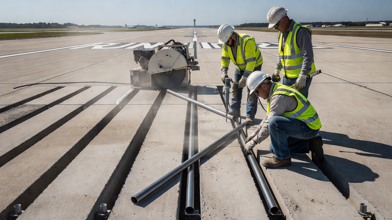
Dowel Bar Retrofit (DBR) is a concrete pavement preservation technique that restores load transfer across existing transverse joints and working cracks by installing dowel bars into slots cut into the hardened concrete. DBR was originally developed in the 1980s through research sponsored by the Federal Highway Administration (FHWA) and first deployed at scale in Puerto Rico, where undoweled JPCP on high-traffic routes was experiencing rapid faulting development. The technique has since been adopted by highway agencies and airport authorities worldwide as a cost-effective alternative to full-depth slab replacement or overlay.
The DBR construction process follows a strict sequence of operations. First, slot cutting is performed using a gang-mounted diamond-blade saw that cuts parallel slots — typically 2.5 to 3 inches (64 to 76 mm) wide and 18 to 24 inches (457 to 610 mm) long — centered on the joint, perpendicular to the joint line. For a standard interstate or runway joint, three to four slots are cut per wheel path, with at least two dowels installed per wheel path. After cutting, the concrete within the slot area is removed, the slot bottom is cleaned, and any standing water is blown out with compressed air. A dowel bar — typically the same diameter as the original design dowels — is placed into each slot, centered on the joint, and supported at the correct elevation using plastic chairs or metal supports. The debonded half of the dowel must be oriented correctly, and a compressible joint filler board is placed at the joint line within the slot to re-form the joint opening.
The dowel is then encapsulated using a high-early-strength patching material — typically a magnesium phosphate concrete, a fast-setting calcium sulfoaluminate cement-based mortar, or a polymer-modified cementitious grout — that achieves the required opening strength within 4 to 6 hours. This rapid strength gain is essential for airport applications where pavement closure windows are severely constrained. The patch material must bond to the existing concrete, match the thermal expansion characteristics of the host slab, and resist the same environmental exposures as the surrounding pavement. After the patch material has cured, the joint is sawed open through the patch to the full joint depth, cleaned, and resealed with a hot-pour or silicone joint sealant to restore the watertight integrity of the joint system.
The performance of DBR under heavy loading has been validated through multiple full-scale accelerated pavement testing programs. The University of California Pavement Research Center conducted Heavy Vehicle Simulator (HVS) testing on DBR-rehabilitated JPCP sections on US 101 near Ukiah, California. The HVS applied a total equivalent loading of approximately 11 million ESALs to each of two DBR sections — one with retrofitted sawn joints and one with retrofitted transverse cracks — without a single fatigue failure occurring in the retrofit patches or dowels. LTE improved from pre-retrofit values in the range of 50 to 60 percent to post-retrofit values exceeding 85 percent, and LTE remained stable throughout the trafficking period. The control section without DBR, in contrast, showed progressive damage to aggregate interlock and declining LTE with trafficking. The Washington State DOT and Minnesota DOT have similarly documented 10 to 15 years of satisfactory DBR performance in field deployments, with the primary failure mode being debonding of the patch material from the host concrete rather than dowel or joint failure.
DBR is appropriate for pavements that meet specific eligibility criteria. The National Concrete Pavement Technology Center (CP Tech Center) recommends DBR for JPCP sections with less than 10 percent slab replacement, average faulting between 3 mm (1/8 inch) and 13 mm (1/2 inch) , and sound concrete in the lower portion of the slab confirmed by coring. Pavements with extensive durability cracking (D-cracking), alkali-silica reactivity (ASR), or severe base erosion are poor candidates because these conditions will continue to deteriorate independently of joint load transfer. DBR is often combined with diamond grinding to restore surface smoothness and profile in a single rehabilitation intervention, achieving both structural improvement at the joints and functional improvement of the riding surface.
Airport portland cement concrete (PCC) pavements present unique challenges for dowel bar design and joint load transfer beyond those encountered in highway pavements. The principal differentiators are the magnitude and configuration of aircraft wheel loads, the spatial distribution of traffic across wide pavement lanes, and the operational criticality that demands near-zero tolerance for joint-related distress that could generate foreign object debris (FOD).
Aircraft gear loads are substantially heavier than highway truck loads and are applied through tire pressures that can reach 200 to 250 psi (1.38 to 1.72 MPa) for wide-body aircraft. The Boeing 777-300ER main landing gear, for example, imparts approximately 55,000 lb (245 kN) per tire on a six-wheel dual-tandem configuration. This loading is applied across a tire contact area roughly 20 inches (508 mm) long by 15 inches (381 mm) wide, resulting in a bearing pressure on the pavement surface that is approximately two to three times greater than a typical highway truck tire. The higher bearing pressure propagates through the slab thickness and concentrates at the dowel-concrete interface, demanding larger-diameter dowels and closer spacing than highway designs.
FAA AC 150/5320-6G specifies dowel dimensions and spacing based on slab thickness (Table 3-6), but additional design considerations apply for specific aircraft and traffic conditions. The FAARFIELD pavement design software incorporates the structural contribution of doweled joints through the finite element response model, accounting for joint stiffness as a function of dowel diameter, spacing, slab thickness, and subgrade support. FAARFIELD’s rigid pavement design module treats joints as planes of reduced stiffness rather than free edges, computing the combined effect of dowel load transfer and aggregate interlock on critical tensile stresses. The software does not directly design the dowels but assumes that dowels meeting Table 3-6 requirements provide load transfer sufficient to achieve the structural credit embedded in the FAA failure model.
Airport joint spacing interacts directly with dowel demand. FAA Table 3-7 provides recommended maximum joint spacings for rigid pavements, typically 15 to 20 feet (4.6 to 6.1 m) depending on slab thickness and subbase type. Shorter joint spacings reduce the absolute magnitude of joint opening and therefore reduce the demands on the joint sealant and dowel alignment tolerances, but they increase the total number of joints — and therefore the total number of dowels — in the pavement. For a 10,000-foot (3,048 m) runway with 18.75-foot (5.7 m) joint spacing, approximately 534 transverse joints must be doweled across the runway width, requiring in excess of 12,800 individual dowel bars for a single runway lane. This scale underscores why minor improvements in dowel material unit cost, placement speed, or durability translate into economically significant lifecycle differences at the project level.
Tie bars — deformed reinforcing bars placed across longitudinal joints — complement dowel bars in the airport joint system. While dowels transfer vertical loads across transverse joints, tie bars prevent longitudinal joints from opening and maintain aggregate interlock load transfer between adjacent paving lanes. Tie bars are not designed to transfer vertical shear; they are intended to hold the longitudinal joint tightly closed. FAA specifications require No. 4 or No. 5 deformed bars, typically 30 to 36 inches (762 to 914 mm) long, spaced at 30 to 40 inches (762 to 1,016 mm) along the longitudinal joint. The distinction between dowel bars (smooth, debonded, transverse joints, shear transfer) and tie bars (deformed, bonded, longitudinal joints, tension retention) is fundamental to understanding the jointed concrete pavement system as an integrated load transfer network.
For in-service airport pavement evaluation, FAA AC 150/5320-6G Chapter 5 and Appendix C provide the framework for assessing joint load transfer as part of a comprehensive structural evaluation. The evaluation process begins with a Pavement Condition Index (PCI) survey per ASTM D5340 to identify joints exhibiting faulting, spalling, or corner cracking — the visible manifestations of inadequate load transfer. Joints with PCI distress ratings of medium or high severity trigger FWD/HWD testing to quantify LTE. The FAA methodology uses the measured LTE in conjunction with backcalculated slab and subgrade moduli to compute the cumulative damage factor (CDF) in FAARFIELD, which determines whether the pavement has sufficient remaining structural life for the projected future traffic. Joints with LTE below 60 to 70 percent in critical runway areas — particularly in the primary touchdown zone — typically prompt consideration of DBR, partial-depth repair, or full-depth slab replacement depending on the extent and severity of deterioration.
The interaction between joint load transfer and stabilized subbases — cement-treated base (CTB), lean concrete base, or asphalt-treated base — introduces additional design considerations for airport pavements. Stabilized subbases provide a stiff, erosion-resistant platform that reduces vertical deflections and maintains uniform support under repeated loading. This reduces the shear demand on dowel bars because a portion of the load transfer occurs through the base layer beneath the joint. However, if the stabilized base cracks or erodes beneath the joint — a common distress in poorly drained pavements — the load previously carried by base support shifts abruptly to the dowels, potentially overloading them. FAA design philosophy therefore treats base layer contribution as a reliability enhancement rather than a substitute for adequate dowel design, and Table 3-6 dimensions apply regardless of subbase type.
In summary, the dowel bar system in airport concrete pavements operates at the intersection of structural mechanics, materials science, construction quality control, and long-term durability management. From initial design per FAA dimensional tables through placement verification with MIT Scan-2, to periodic LTE measurement with FWD/HWD, and ultimately to rehabilitation via dowel bar retrofit when performance degrades, every phase of the dowel bar lifecycle demands rigorous engineering attention. The consequences of underperformance — faulted joints, FOD-generating spalls, and unplanned runway closures — reinforce why this seemingly simple steel bar remains one of the most carefully studied and specified components in airport pavement engineering.
Assess and improve load transfer in your airport concrete pavements with expert evaluation, dowel bar retrofit design, and construction support. Ensure long-term pavement performance.
Tie bars are deformed steel bars placed across longitudinal joints in concrete pavement to prevent lane separation and hold adjacent slabs tightly together. Unl...
Transverse joints are sawed or formed cuts across PCC pavement slabs at regular spacing (typically 4.5-6 m for JPCP) to control transverse cracking from thermal...
Load transfer devices (dowel bars, tie bars, aggregate interlock, keyed joints) transfer wheel loads across joints and cracks in concrete pavements, preventing ...