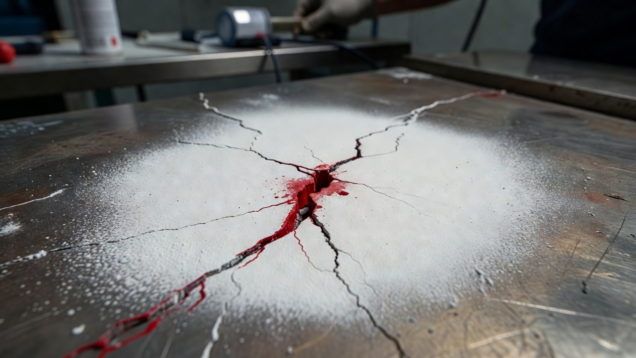
Dye Penetrant Testing (PT) is a surface NDT method where a colored or fluorescent liquid penetrant is applied to a clean surface, drawn into surface-breaking discontinuities by capillary action, then revealed by a developer after excess penetrant is removed. It detects cracks, porosity, and laps in non-porous materials (metals, ceramics, some plastics). Covers procedure, sensitivity levels, and applications in steel and concrete inspection.
Dye Penetrant Testing (PT) for Surface Defects
Principle of Operation: Capillary Action
Dye Penetrant Testing (PT), also designated as Liquid Penetrant Inspection (LPI) or Penetrant Testing (PT), is a surface non-destructive testing method that detects discontinuities open to the surface in non-porous materials. The method is among the oldest NDT techniques, originating in the late 1800s when railroad maintenance shops used the oil-and-whiting method — immersing parts in used machine oil, wiping off excess, then coating with powdered chalk. Oil trapped in surface cracks would bleed out and stain the white coating, revealing defects through a principle still used in modern penetrant testing.
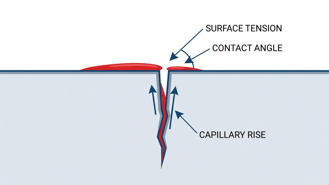
The physical foundation of PT is capillary action, the tendency of a liquid to penetrate or migrate into small openings without external forces. Capillary action occurs when the adhesive forces between the liquid molecules and the solid surface are stronger than the cohesive forces within the liquid itself. For a liquid in a narrow opening such as a crack, the rise height follows the capillary rise equation: h = (2γ cos θ) / (ρgr), where h is the capillary rise height, γ is surface tension, θ is the contact angle between the liquid and the solid surface, ρ is liquid density, g is gravity, and r is the crack or pore radius. Critically, this equation reveals that capillary force increases as flaw size decreases — smaller discontinuities exert stronger capillary draw, a counterintuitive but essential property that makes PT capable of detecting nanometer-scale surface openings.
The contact angle (θ) determines whether a liquid will wet a surface and enter a crack. A contact angle of 0° produces complete wetting and spontaneous spreading across the surface. Angles approaching 90° or greater cause the liquid to bead up and resist entry into tight openings. Commercial penetrants are formulated to achieve very low contact angles on metal surfaces through the addition of surfactants and wetting agents that reduce surface tension from the 72 dynes/cm of water down to the 25-35 dynes/cm range typical of penetrants. This ensures thorough surface coverage and efficient capillary entry into the finest defects.
Surface tension is the force required to expand or pull apart the surface of a liquid, caused by cohesive forces holding surface molecules together. These forces cause liquid droplets to assume spherical shapes — the smallest surface area for a given volume. Penetrant performance depends critically on surface tension. If the surface tension is too high, the penetrant will not enter tight cracks. If too low, the penetrant may run off vertical surfaces or be difficult to remove from the surface without also removing penetrant from defects. Penetrant manufacturers carefully balance surface tension through proprietary formulations of carrier fluids, surfactants, and dyes.
An important consideration in capillary action is the behavior of trapped gas in closed-end flaws. When a crack or void does not extend fully through the material, the advancing penetrant compresses the air or gas trapped at the flaw tip. This compressed gas creates a back-pressure that opposes further capillary penetration, eventually reaching equilibrium when capillary pressure equals gas pressure. This is why the developer step is essential — the developer physically draws the trapped penetrant back out through reverse capillary action, creating the visible indication at the surface.
Modern penetrant testing emerged during World War II when the aircraft industry needed to inspect non-ferrous aluminum and magnesium alloys that could not be inspected with magnetic particle testing. The addition of fluorescent dyes to penetrating oils in 1941 marked a major advancement, dramatically improving sensitivity. Red visible dyes followed shortly after. Post-war developments included standardized emulsifiers, water-washable formulations, multiple sensitivity levels, and the qualification system defined by SAE AMS 2644 that governs penetrant materials today.
Penetrant Types and Classification System
The universal classification for penetrant inspection materials is defined by SAE AMS 2644 — Inspection Material, Penetrant. This specification governs penetrant material performance requirements, classification, qualification, and Qualified Products List (QPL) approval. Materials must pass qualification testing at the Air Force Research Laboratory, Wright-Patterson AFB, Dayton, Ohio and be listed on QPL-AMS-2644 before they can be used in aerospace and defense applications. The classification system has four primary categories: Type, Method, Level, and Form, with an additional Class designation for solvent removers.
Type Classification
Type I — Fluorescent Penetrant: These penetrants contain chemical compounds that emit visible light when exposed to UV-A radiation (320-400 nm, peak at 365 nm). The fluorescence mechanism involves electrons absorbing photon energy from UV light, jumping to a higher orbital shell, then returning to equilibrium by releasing energy as longer-wavelength visible light, typically yellow-green at 510-560 nm. This wavelength range corresponds to the peak sensitivity of the dark-adapted human eye under scotopic vision conditions. Type I penetrants provide the highest detection sensitivity because even minute quantities of penetrant produce highly visible indications against a dark background. The sensitivity of fluorescent penetrants is further enhanced by the human eye’s ability to detect faint light sources in dark conditions — the absolute threshold of human vision is approximately 10⁻⁶ candelas per square meter, making fluorescent indications visible at extremely low concentrations.
Type II — Visible (Color-Contrast) Penetrant: These penetrants contain a red dye (typically azo dyes such as Solvent Red 164 or C.I. Solvent Red 24) dissolved in a penetrating oil vehicle. They are viewed under natural or white light against a white developer background that provides the necessary contrast. Type II penetrants are simpler to use because they require no UV light source, making them ideal for field inspections, spot checks, and applications where electricity is unavailable. However, the United States Department of Defense prohibits the use of visible penetrant on aircraft, engines, and missiles except for parts with specific written engineering approval, due to their lower sensitivity compared to fluorescent methods.
Type III — Dual-Mode Penetrant: These penetrants are visible under both white light and UV light, though with reduced visibility in both modes compared to dedicated Type I or Type II penetrants. They are used in specialized applications where both inspection modes may be needed.
Method Classification
The Method classification defines how excess penetrant is removed from the surface after the dwell period.
Method A — Water-Washable (Self-Emulsifying): The penetrant contains an emulsifier as an integral component of the penetrant vehicle, permitting direct water removal after dwell. This method is fast, convenient, and works well on rough surfaces, threaded or grooved parts, holes, and orifices. The water spray must not exceed 40 psi (276 kPa) pressure, water temperature must be between 50-100°F (10-38°C), and the spray must be a coarse spray from a minimum distance of 12 inches (30 cm). Despite its convenience, the US Air Force and Navy prohibit Method A on all flight-critical aircraft components and all engine components without specific written engineering approval, due to the risk of over-washing and removing penetrant from shallow discontinuities.
Method B — Post-Emulsifiable Lipophilic: The penetrant is formulated for optimal penetrating and visibility characteristics but contains no emulsifier. After penetrant dwell, a separate oil-based emulsifier (lipophilic, meaning “oil-loving”) is applied to the part surface. The emulsifier chemically diffuses into the excess surface penetrant over a precisely controlled emulsification dwell time, converting it into a water-removable mixture. The emulsification time is critical — too little time leaves unremovable penetrant on the surface, while too much time allows the emulsifier to diffuse into penetrant trapped in discontinuities, washing out defect indications. Method B is also prohibited on critical rotating engine components per military specifications.
Method C — Solvent-Removable: Excess penetrant is removed using solvent applied with clean lint-free cloths or paper towels. Solvent-removable penetrants are most often used for spot inspections, field applications, and portable testing where water is unavailable or access is limited. The procedure is deceptively simple — the technician must wipe the surface with a cloth slightly dampened with solvent, using a fresh area of cloth for each wipe, and avoid applying solvent directly to the surface which could wash penetrant out of defects. Solvent removers are classified as Class 1 (halogenated), Class 2 (nonhalogenated), or Class 3 (special application) based on chemical composition.
Method D — Post-Emulsifiable Hydrophilic: This method uses a water-based remover solution (hydrophilic, meaning “water-loving”) that is supplied as a concentrate and diluted with water for use. Removal works through detergent and surfactant action rather than chemical diffusion — surfactants in the hydrophilic remover break the excess surface penetrant into small droplets and prevent reattachment to the surface. The process involves a pre-rinse with water, immersion or spray application of the hydrophilic remover with agitation, followed by a final water rinse. Method D is the standard method used by the aerospace industry because it provides excellent removal control without the risk of emulsifier diffusion into defect-trapped penetrant.
Sensitivity Levels
Sensitivity levels apply to Type I (fluorescent) penetrants only — Type II and Type III penetrants are classified solely as Level 1 (low sensitivity). The five sensitivity levels are:
Level
Designation
Typical Application
Level ½
Ultra-low sensitivity
Rough surfaces, forged surfaces, high background tolerance
Level 1
Low sensitivity
General inspections, automotive components, less critical parts
Level 2
Medium sensitivity
Most general-purpose aerospace applications
Level 3
High sensitivity
Safety-critical aerospace components, flight-critical parts
Level 4
Ultra-high sensitivity
Turbine blades, rotating components, most demanding applications
Sensitivity qualification testing uses titanium or nickel alloy panels containing laboratory-generated fatigue cracks of known sizes for fluorescent penetrants, and thermally cracked aluminum blocks for visible penetrants. Manufacturers submit samples to Wright-Patterson AFB, which assigns sensitivity levels based on standardized comparison tests. The correct sensitivity is the one that maximizes indication contrast — not necessarily the highest level. Higher sensitivity penetrants detect smaller cracks but produce stronger background fluorescence that can mask indications. A penetrant that is too sensitive for the surface condition can produce unacceptably high background that reduces detection reliability.
Developer Forms
The developer is the material applied after excess penetrant removal that draws trapped penetrant out of discontinuities and spreads it laterally to create a visible indication.
Form a — Dry Powder: Finely divided inert powders (talc, silica, calcium carbonate, magnesium carbonate, kaolin, or similar absorbent minerals) applied by dusting, immersion, or automated cloud chamber. The part must be completely dry before application. Dry powder developers produce a thin, non-uniform coating and are best suited for rough surfaces.
Form b — Water-Soluble: White powders that dissolve completely in water, forming a uniform film upon drying. Not recommended for use with water-washable penetrants because the soluble developer may act as an additional emulsifier and wash penetrant out of defects.
Form c — Water-Suspendible: Insoluble white powders suspended in water. Requires constant agitation to maintain suspension. Produces a uniform coating layer.
Form d — Nonaqueous Solvent-Based (Type I): White powder suspended in a volatile organic solvent carrier that evaporates rapidly. The aerosol spray format makes this the most common developer for fluorescent penetrant inspection, providing a thin, uniform, opaque white coating.
Form e — Nonaqueous Solvent-Based (Type II): Similar to Form d but formulated specifically for visible (red dye) penetrants. The white background provides maximum contrast for the red indications.
Form f — Special Application: For customized requirements such as high-temperature environments or specific material compatibility constraints.
Solvent Remover Classes
Solvent removers used in Method C are classified into three groups based on chemical composition:
Class 1 — Halogenated: Contain chlorine or fluorine compounds (historically 1,1,1-trichloroethane, now largely restricted under environmental regulations). High solvency power but environmental and health concerns limit their use.
Class 2 — Nonhalogenated: Aliphatic or aromatic hydrocarbon blends. Lower solvency than halogenated solvents but safer for health and the environment. Most commonly used in field inspections.
Class 3 — Special Application: For specific material compatibility requirements, such as low sulfur and chlorine content for titanium or austenitic stainless steel applications.
The Six-Step PT Procedure
The penetrant testing procedure follows a strictly defined sequence of six steps. Deviation from or omission of any step can result in failure to detect defects.
Step 1: Surface Preparation (Pre-Cleaning)
Surface preparation is the single most critical step in the entire PT process. The surface must be free of all contaminants that could block penetrant entry into discontinuities: dirt, oil, grease, paint, coatings, corrosion products, scale, welding flux, slag, moisture, and chemical residues. If the penetrant cannot enter the defect, the inspection will produce a false negative result regardless of subsequent procedural precision.
Contaminant removal methods:
Solvent cleaning — Using industrial solvents or proprietary cleaners to dissolve oils, greases, and organic contaminants
Detergent cleaning — Aqueous alkaline cleaners for general surface contamination
Vapor degreasing — Condensing solvent vapor on the part surface for precision cleaning
Chemical etching — Required when mechanical operations have smeared or peened metal over surface openings. Shot peening, honing, abrasive blasting, buffing, grinding, and sanding can all close surface openings and must be followed by chemical etching if these operations occurred prior to PT
Paint stripping — All organic coatings must be completely removed — PT cannot be performed over paint, primer, plating, or any coating system
Critical surface preparation restrictions: Mechanical cleaning methods that smear or peen metal must precede PT only if effective chemical etching is performed afterward to re-open surface-breaking discontinuities. The military technical manual USAF TO 33B-1-1 explicitly prohibits performing PT over organic coatings and requires complete removal of coatings before inspection.
Step 2: Penetrant Application
Penetrant is applied to the prepared surface by dipping, spraying, brushing, or flooding. The entire inspection surface must be completely and uniformly covered. For parts with complex geometries, dipping ensures complete coverage. For large structures or field applications, spray application using aerosol cans or spray equipment is standard. The penetrant application marks the beginning of the dwell time.
Step 3: Penetrant Dwell Time
The dwell time is the period during which the penetrant remains on the surface, allowing capillary action to draw it into surface-breaking discontinuities. Dwell time is not a fixed value — it depends on material type, product form, expected defect type, penetrant sensitivity, and temperature. The following dwell time guidelines are from ASME Section V, Article 6:
Material
Product Form
Expected Discontinuities
Dwell Time (minutes)
Carbon steel, low-alloy steel
Welds
Cracks, lack of fusion, porosity
5
Aluminum, magnesium, stainless steel
Wrought forms
Cracks, laps
10
Cast aluminum, cast magnesium
Castings
Cracks, shrinkage, porosity
10
Steel, titanium, high-temp alloys
Castings
Cracks, shrinkage, porosity
20
Most materials
All forms
Tight cracks, very fine defects
30-60
Temperature effects on dwell time: The normal temperature range for PT is 50-125°F (10-52°C). For test object temperatures between 40-50°F (4-10°C), dwell time must be doubled. Below 40°F (4°C), PT is not recommended because penetrant viscosity increases significantly, reducing capillary action. Above 125°F (52°C), penetrant may evaporate and fluorescent dyes may suffer heat fade — permanent loss of fluorescence brightness.
Important dwell time considerations: There is generally no harm in using longer dwell times provided the penetrant does not dry on the surface. If the penetrant dries during dwell, it cannot be adequately removed and will produce high background that masks defect indications. Dwell time should be increased for tight cracks, fatigue cracks, and stress corrosion cracks that are expected to be very fine.
Step 4: Excess Penetrant Removal
Excess penetrant removal is the most operator-sensitive step and the most common source of false negatives. The removal method must eliminate all surface penetrant while leaving penetrant trapped in discontinuities undisturbed.
Method A — Water-Washable Removal: Water spray at pressure not exceeding 40 psi (276 kPa), water temperature 50-100°F (10-38°C), using a coarse spray pattern from a minimum distance of 12 inches (30 cm). The spray should be directed to sweep penetrant off the surface rather than blast it. Over-washing is the single most common cause of false negatives in Method A.
Method B — Lipophilic Post-Emulsifiable Removal: Apply lipophilic emulsifier by immersion or flood for the manufacturer-specified emulsification dwell time (typically 1-5 minutes). Then rinse with water spray. The emulsification time is critical — insufficient time leaves unremovable surface penetrant, while excessive time allows the emulsifier to diffuse into defects and wash out indications.
Method C — Solvent-Removable Removal: Wipe the surface with a clean, lint-free cloth slightly dampened with solvent. Use a fresh area of the cloth for each wipe. Do not apply solvent directly to the surface — this will wash penetrant out of discontinuities. Repeat wiping with clean cloth areas until the cloth shows no penetrant residue.
Method D — Hydrophilic Post-Emulsifiable Removal: Pre-rinse with water to remove bulk surface penetrant. Immerse or spray with hydrophilic remover solution (typically 1-5% concentration in water) with gentle agitation for the manufacturer-specified time (typically 2-5 minutes). Final rinse with clean water.
Step 5: Drying and Developer Application
After excess penetrant removal, the part must be dried before developer application. Drying is typically accomplished by:
Air drying at ambient temperature (for solvent-removable methods)
Forced hot air at temperatures not exceeding 160°F (71°C) — higher temperatures can damage fluorescent dyes
Warm air cabinet with controlled temperature and air circulation
The developer is then applied according to the manufacturer’s instructions. The developer serves three functions:
Physical absorption — Draws trapped penetrant out of discontinuities through reverse capillary action
Contrast enhancement — Provides a uniform white background for visible red dye (Type II) or a dark/UV-absorbent background for fluorescent (Type I) penetrants
Indication spreading — Lateral spreading of penetrant within the developer layer enlarges the visible indication, making fine defects more apparent
Developer Dwell Time: After developer application, a minimum of 10 minutes is required for reverse capillary action to fully draw trapped penetrant out of discontinuities. The inspection must be performed within 10-60 minutes after developer application. After 60 minutes, indications can bleed out too far and diffuse, making interpretation invalid.
Step 6: Inspection and Evaluation
The final step is visual examination of the developed surface for indications.
For Type I (Fluorescent) Penetrant: Inspection is performed in a darkened area with ambient white light limited to 8-20 lux (depending on specification). The surface is illuminated with UV-A light (black light) at a wavelength of 320-400 nm with peak at 365 nm. Minimum UV-A intensity at the inspection surface is typically 1,000 µW/cm² (10 W/m²). The inspector must allow dark adaptation time (5-10 minutes minimum) for maximum visual sensitivity. Indications appear as bright yellow-green areas against a dark background.
For Type II (Visible) Penetrant: Inspection is performed under adequate white light of minimum 500 lux (50 foot-candles) at the inspection surface. Indications appear as bright red marks against a white developer background.
Evaluation criteria include:
Indication size — Length and width of the indication
Indication shape — Round, linear, or irregular
Indication location — Position relative to weld, stress concentration, or geometric features
Indication frequency — Isolated or clustered indications
Indication alignment — Orientation relative to expected stress directions
Acceptance criteria are defined by the applicable standard or specification (AWS D1.5 for bridge welds, ASME Section VIII for pressure vessels, customer specifications for aerospace components). All indications exceeding acceptance limits must be marked for evaluation or repair.
Post-inspection cleaning: All penetrant materials must be completely removed from the part after inspection to prevent chemical attack, cosmetic staining, or interference with subsequent processes such as painting, welding, or heat treatment.
Chemical Compositions of Penetrant Materials
The penetrant vehicle (the liquid base) is typically petroleum oil — high-boiling-point kerosene fractions, mineral oils, or proprietary hydrocarbon blends. Key physical properties specified by AMS 2644 include: viscosity (affects entry speed into cracks — high viscosity enters slowly but clings better to vertical surfaces), specific gravity (typically less than 1.0 since most penetrants are organic and lighter than water; water contamination sinks to the tank bottom), flash point (minimum 200°F or 93°C for open-tank use per AMS 2644), and volatility (low volatility preferred to minimize evaporation, drying on parts, fire hazard, and toxicity).
Fluorescent dyes used in Type I penetrants are based on coumarin, naphthalimide, or benzoxazole derivatives. These compounds are selected for their high quantum efficiency (conversion of absorbed UV light to visible light), photostability (resistance to fading under UV exposure), and solubility in the penetrant vehicle. The dyes are formulated to emit at 510-560 nm (yellow-green), which corresponds to the peak sensitivity of the dark-adapted human eye.
Visible dyes in Type II penetrants are red azo dyes such as Solvent Red 164 or C.I. Solvent Red 24. These dyes provide maximum contrast against the white developer background and are soluble in the hydrocarbon vehicle system.
Emulsifiers:
Lipophilic emulsifiers (Method B) — Oil-based surfactants, ready-to-use. Work through chemical diffusion into the surface layer of penetrant.
Hydrophilic emulsifiers (Method D) — Water-based concentrates (typically nonionic surfactants combined with detergents), diluted with water before use. Work through detergent action without chemical diffusion into defect-trapped penetrant.
Developers:
Dry powder (Form a) — Finely divided inert powders such as talc, silica, calcium carbonate, magnesium carbonate, or kaolin
Water-soluble (Form b) — Modified starches or synthetic polymers that dissolve completely in water
Water-suspendible (Form c) — Insoluble white powders suspended in water with suspension agents
Nonaqueous (Forms d/e) — White powder suspended in volatile organic solvent (typically acetone, isopropanol, or similar rapid-evaporation carriers)
Chemical restrictions apply for specific materials. Sulfur and halogen limits are required when testing austenitic stainless steels (to avoid embrittlement during subsequent heat treatment) and titanium alloys (to avoid corrosion at elevated temperatures). Low-sulfur/low-chlorine penetrants (typically less than 200 ppm each) are available for these applications. Oxygen compatibility requires non-oil-based penetrants for oxygen system components because oil residues can explode or burn violently in oxygen.
Sensitivity Levels in Detail
The sensitivity level of a penetrant system is the most important factor in determining its ability to detect fine defects. The sensitivity-background tradeoff is the fundamental engineering consideration: higher sensitivity penetrants detect smaller cracks but produce stronger background fluorescence that can mask indications. Lower sensitivity penetrants have less background but cannot detect the finest indications. The correct sensitivity is the one that maximizes indication contrast — the ratio of indication brightness to background brightness.
Level ½ (Ultra-Low Sensitivity): Used primarily for surfaces with significant roughness, such as as-forged or as-cast surfaces. The high background that would be produced by a higher-sensitivity penetrant on these rough surfaces would mask any defect indications. Level ½ penetrants are formulated to minimize background while still providing adequate sensitivity for the defect sizes of concern on rough surfaces.
Level 1 (Low Sensitivity): Suitable for general industrial inspections where the defect size of interest is relatively large. Common in automotive, heavy equipment, and structural steel fabrication where specifications do not require detection of very fine cracks.
Level 2 (Medium Sensitivity): The most common sensitivity level for general-purpose aerospace manufacturing and maintenance. It balances detection capability with acceptable background levels on most surfaces.
Level 3 (High Sensitivity): Required for safety-critical aerospace components including flight control systems, primary structural elements, and pressure vessels. Level 3 penetrants can detect fatigue cracks in the range of 1-3 µm in width.
Level 4 (Ultra-High Sensitivity): The highest available sensitivity, used for the most demanding applications including turbine engine rotating components (disks, blades, shafts), where a single undetected crack could result in catastrophic failure. Level 4 penetrants can detect cracks as fine as 150 nm under optimal conditions but require extremely clean surfaces and careful processing to manage background levels.
The selection of sensitivity level should be based on the governing specification for the component being inspected. When no specification dictates the sensitivity level, evaluation on actual production parts with known defect types is recommended to determine the optimal sensitivity for the specific application.
PT for Steel Bridge Inspection
The Federal Highway Administration (FHWA) recognizes dye penetrant testing as a valid NDT method for steel bridge inspection, particularly for detecting surface-breaking cracks in welded connections, fracture-critical members, and fatigue-prone details. PT is applied to bridge components where magnetic particle testing (MT) cannot be used due to non-ferromagnetic materials or access constraints.
Applications in bridge inspection:
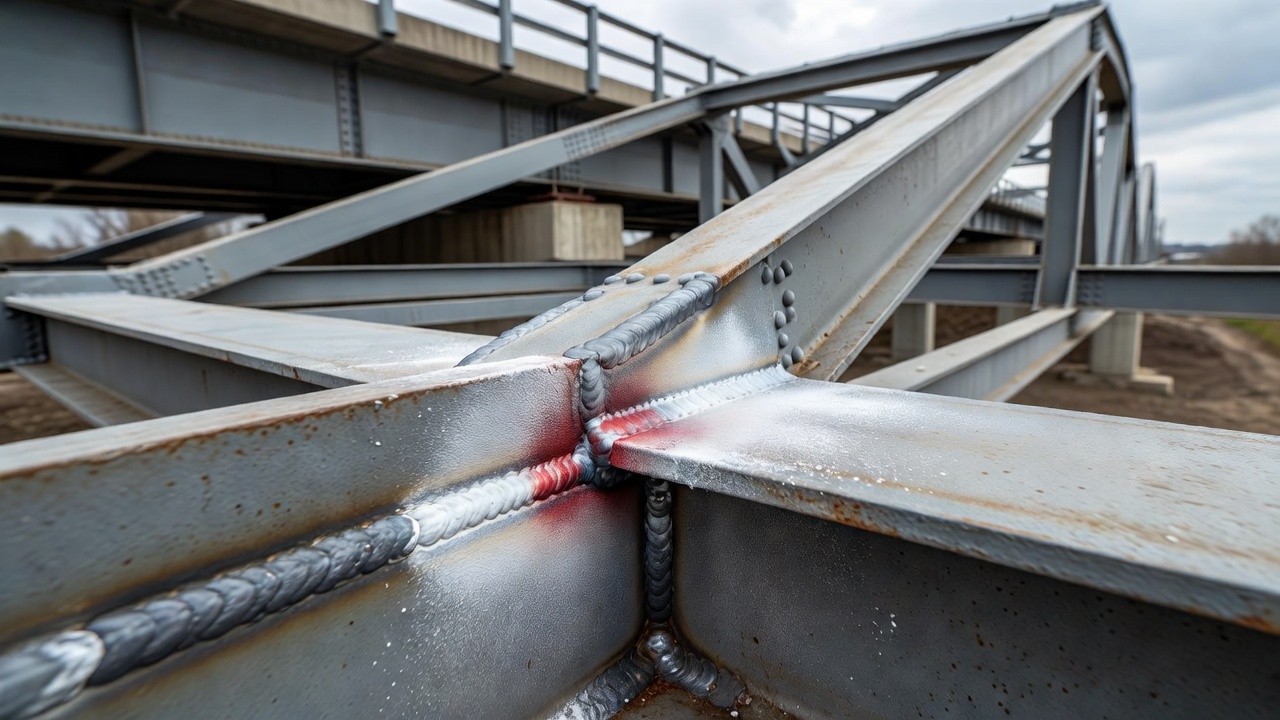
Weld inspections — Surface-breaking cracks in welded girder connections, cover plate terminations, stiffener-to-flange welds, and field splice welds
Fatigue crack detection — Cracks at weld toes, cope holes, diaphragm connections, and other stress concentration points on fracture-critical members
Base metal crack detection — Cracks in rolled shapes, gusset plates, and connection plates
Anchor bolt and pin inspection — Thread roots, fillet radii, and stress concentration zones in bridge bearings, pins, and hangers
Procedure for bridge field inspection: Bridge PT is typically performed using the solvent-removable (Method C) method with visible dye (Type II) penetrant in portable aerosol kits. The procedure involves: cleaning the inspection area with solvent to remove dirt, grease, and loose rust; grinding or wire brushing to expose bare metal if necessary; applying penetrant by aerosol spray with appropriate dwell time (10-20 minutes for fatigue crack detection); removing excess penetrant with solvent-dampened cloths; applying nonaqueous developer (Form e) from aerosol spray; and inspecting after 10-60 minutes developer dwell time under adequate white light.
Limitations for bridge inspection: PT can only detect surface-breaking defects — internal defects, embedded slag, or subsurface fatigue cracks that have not propagated to the surface cannot be detected. Rough weld surfaces can produce false indications from penetrant trapped in surface irregularities. PT requires the bridge member surface to be at the appropriate temperature (50-125°F, 10-52°C) and free of coatings. Paint must be stripped from the inspection area before PT can be performed. After inspection, all penetrant residues must be cleaned from the bridge member.
PT for Weld Inspection
Dye penetrant testing is widely used for weld inspection in fabrication shops and field construction. It is specified as an acceptance method in several welding codes including AWS D1.1 (Structural Welding Code — Steel) and AWS D1.5 (Bridge Welding Code). PT is typically applied to welds where radiography or ultrasonic testing cannot provide adequate coverage due to joint geometry, access limitations, or material thickness considerations.
Types of weld discontinuities detectable by PT:
Discontinuity
Description
Typical PT Indication
Hot cracks
Solidification cracks that form at elevated temperatures during weld cooling
Irregular, branching linear indications along weld centerline
Cold cracks
Hydrogen-induced or delayed cracking in the heat-affected zone
Sharp, straight linear indications typically parallel to weld axis
Crater cracks
Cracks at the termination point of the weld bead
Star-shaped or multiple short linear indications at the crater
Porosity
Gas pockets trapped in solidifying weld metal
Round, circular indications distributed throughout the weld
Lack of fusion
Incomplete fusion between weld metal and base metal or between successive weld beads
Smooth, elongated linear indications at the fusion line
Undercut
Groove melted into the base metal at the weld toe that was not filled
Linear indication at the weld toe
Surface slag inclusions
Non-metallic slag trapped at the weld surface
Irregular, globular indications
Pinholes
Very small individual gas pores
Fine dot indications, often in clusters
PT procedure for weld inspection: Weld surfaces must be cleaned to bare metal, removing all slag, spatter, grinding dust, and oxides. For welds with tight geometry (narrow groove welds, fillet welds in corners), penetrant dwell time should be increased to 15-20 minutes to ensure adequate penetration. Developer should be applied in a thin, uniform coat — excessive developer can mask fine indications. Inspection should focus on the weld face, weld toes (where fatigue cracks typically initiate), and the heat-affected zone adjacent to the weld.
Advantages of PT for weld inspection:
Low cost compared to radiographic testing (RT) or ultrasonic testing (UT)
Portable — can be performed in the field on erected structures without power requirements (visible dye method)
Visual clarity — indications are clearly visible on the weld surface, providing immediate confirmation of defect presence
No special power requirements for visible-dye method
Can inspect welds on non-ferromagnetic materials (austenitic stainless steels, aluminum, titanium)
Limitations for weld inspection:
Surface-breaking only — embedded slag, internal lack of fusion, or volumetric defects are not detected
Rough weld surfaces can create false indications from penetrant trapped in surface roughness
Post-cleaning required — penetrant residues must be removed from welds that will later be painted or placed in service
Temperature constraints — weld temperature must be within the specified range (40-125°F, 4-52°C)
Weld surfaces must be thoroughly cleaned before PT
Acceptance criteria for weld indications: AWS D1.5 (Bridge Welding Code) specifies that any linear indication (length greater than three times width) is unacceptable. Rounded indications (length equal to or less than three times width) must meet specific size limits based on the weld thickness. Indications occurring at a rate of more than four in any 6-inch (150 mm) weld length are also unacceptable regardless of individual size.
PT for Concrete — Fundamental Limitations
Dye penetrant testing is fundamentally unsuitable for concrete and other porous materials. This limitation is clearly stated in all authoritative NDT references including ASTM E1417, SAE AMS 2644, and USAF TO 33B-1-1. Understanding why PT fails on concrete is essential for inspectors and engineers planning NDT programs.
Why PT fails on concrete:
Absorption into bulk material — Concrete is a highly porous material with a complex pore structure, capillary voids, and microcracks throughout its volume. When penetrant is applied, it seeps into this intrinsic porosity rather than remaining localized in specific defect locations. The penetrant is absorbed throughout the entire surface area, not just at crack openings.
Retention of penetrant — Once penetrant enters the concrete’s porous structure, it cannot be removed by any practical method. Wiping, solvent cleaning, or water washing cannot extract penetrant from the interconnected pore network. This leaves permanent staining on the concrete surface.
No defect-specific indications — Developer applied to a penetrant-soaked porous surface shows uniform coloration rather than localized indications at defect locations. The entire surface fluoresces or shows red coloration, making it impossible to distinguish between intrinsic porosity and actual cracks.
False positives — The uniform absorption of penetrant into the concrete surface produces indications across the entire inspected area, which could be misinterpreted as widespread defects.
Alternative methods for concrete crack detection:
Visual inspection — Direct observation with crack width measurement using crack microscopes or graduated comparator cards
Ultrasonic Pulse Velocity (UPV) — Detects internal cracks and measures crack depth through changes in pulse transit time
Impact-Echo — Detects delaminations and planar cracks through stress wave reflection analysis
Ground Penetrating Radar (GPR) — Can detect moisture-filled cracks and subsurface anomalies
Infrared Thermography — Detects delaminations and moisture accumulation through surface temperature patterns
Proprietary water-based dye stains — Some specialized products exist for concrete surface crack mapping, but these are not classified as penetrant testing under AMS 2644 or ASTM E165
Other materials incompatible with PT:
Anodized aluminum — The porous anodic coating absorbs penetrant, producing high background
Powdered-metal products — Inherent connected porosity absorbs penetrant throughout the part
As-cast surfaces with high roughness — Mechanical trapping of penetrant in surface irregularities
Graphite and carbon materials — Porosity and absorption issues
Wood and particle board — Highly porous
Organic coatings (paint, varnish, plating) — Must be completely stripped before PT
Dense ceramics with open porosity — Testing limited to fully dense, glazed ceramics
PT vs Magnetic Particle Testing (MT)
Dye penetrant testing and magnetic particle testing are complementary surface NDT methods that share some applications but have fundamentally different physical principles and capabilities. Understanding when to use PT versus MT — and when to use both — is critical for effective inspection planning.
Capability
Penetrant Testing (PT)
Magnetic Particle Testing (MT)
Material restriction
Non-porous materials only
Ferromagnetic materials only (iron, nickel, cobalt, and their alloys — primarily steel)
Detectable discontinuities
Surface-breaking only
Surface and near-surface (subsurface up to 1-2 mm)
Non-magnetic materials
Works on all non-porous (Al, Ti, Cu, Mg, plastics, ceramics)
Cannot be used on non-ferromagnetic materials
Complex geometries
Excels on complex geometries (all surfaces covered at once)
Requires magnetic field setup; complex geometries may need multiple magnetizations
Surface is rough or has thin coatings that cannot be stripped
PT chemical handling and disposal are undesirable
Complementary use in aerospace and bridge inspection: In many facilities, both methods are used on the same component — MT on steel parts and PT on aluminum alloy parts of the same assembly. For example, aircraft landing gear assemblies typically use MT on steel components (axles, pistons) and PT on aluminum components (forgings, castings) using the same inspection station with different processing procedures.
Standards Governing PT
Dye penetrant testing is governed by a comprehensive framework of international, national, and industry-specific standards that define material requirements, procedures, calibration, personnel qualification, and acceptance criteria.
ASTM E1417/E1417M — Standard Practice for Liquid Penetrant Testing: The primary process standard for PT in the United States. It establishes minimum requirements for conducting liquid penetrant examination of nonporous metal and nonmetal components. It replaces MIL-STD-6866. The standard covers all Type/Method/Level/Form/Class combinations from SAE AMS 2644 and defines general procedures, calibration requirements, and reporting. Applicable to in-process, final, and maintenance (in-service) examinations.
ASTM E165/E165M — Standard Practice for Liquid Penetrant Testing for General Industrial Components: Contains detailed how-to information for developing the detailed procedures required by E1417. Covers equipment requirements, surface preparation, penetrant application, dwell time, removal techniques, developer application, inspection, evaluation, and reporting. This is the standard most often referenced in industrial and infrastructure PT specifications.
SAE AMS 2644 — Inspection Material, Penetrant: The classification standard for penetrant materials. Defines Type (I fluorescent, II visible, III dual), Method (A water-washable, B lipophilic PE, C solvent-removable, D hydrophilic PE), Level (½, 1, 2, 3, 4), Form (a dry powder, b water-soluble, c water-suspendible, d/e nonaqueous, f special), and Class (1 halogenated, 2 nonhalogenated, 3 special). Governs qualification testing and QPL listing through Wright-Patterson AFB.
ASME Section V, Article 6 — Liquid Penetrant Examination: Governs PT in pressure vessel and boiler applications. Specifies dwell times, temperature correction factors, developer dwell times, and acceptance criteria for nuclear and pressure vessel components. The dwell time tables from Article 6 are the most widely referenced in industry.
AWS D1.5 — Bridge Welding Code: References PT as an acceptable NDT method for weld inspection in steel bridge fabrication and field welding. Defines acceptance criteria for PT indications in bridge welds.
AWS D1.1 — Structural Welding Code — Steel: References PT for weld inspection in general structural steel applications. Defines procedures and acceptance limits.
ISO 3452 — Non-Destructive Testing — Penetrant Testing: The international standard series covering PT. ISO 3452-1 covers general principles, ISO 3452-2 covers testing of penetrant materials, ISO 3452-3 covers reference test blocks, and ISO 3452-4 covers equipment.
NAS-410 — Certification and Qualification of Nondestructive Test Personnel: Governs NDT personnel certification in the aerospace industry. Defines training hours, experience requirements, and examination requirements for PT personnel at Level I, II, and III. Also referenced by ASNT SNT-TC-1A for industrial applications.
USAF TO 33B-1-1 / NAVAIR 01-1A-16-1 / TM 1-1500-335-23 — Joint Tri-Service Technical Manual: The most comprehensive procedural document for penetrant inspection of military aircraft. Contains detailed requirements for all aspects of PT including material qualification, process control, dwell times, sensitivity verification, and equipment requirements.
Advantages and Limitations of PT
Advantages
High sensitivity to fine surface defects. Fluorescent penetrant testing at Level 3-4 sensitivity can detect surface-breaking cracks as narrow as 150 nanometers. This sensitivity makes PT one of the most effective methods for detecting fatigue cracks, stress corrosion cracks, and other fine surface discontinuities in critical components.
Applicable to a wide range of materials. PT works on virtually any non-porous material: all metals (ferrous and non-ferrous), ceramics, glasses, certain plastics, and composites. This versatility makes PT applicable across aerospace, automotive, power generation, chemical processing, bridge inspection, and general manufacturing.
Complex geometry capability. Because penetrant is applied as a liquid that conforms to any surface, PT can inspect complex geometries that are difficult or impossible to test with other NDT methods. Threaded parts, gears, splined shafts, and internal passages can all be inspected simultaneously.
Large area inspection. PT can inspect large surface areas in a single process. Batch processing of multiple small parts is efficient. For large structural components, the entire critical area can be inspected in one application.
Portable and field-deployable. Aerosol penetrant kits enable PT to be performed anywhere without external power or specialized equipment. This makes PT ideal for field inspection of bridges, pipelines, storage tanks, and in-service equipment.
Immediate visual results. PT indications are directly visible on the surface, providing immediate confirmation of defect location, size, and orientation. No signal interpretation or complex data analysis is required.
Low initial equipment cost. Compared to ultrasonic, radiographic, or eddy current testing, PT requires minimal capital investment. The primary costs are consumable penetrant materials.
Limitations
Surface-breaking defects only. PT cannot detect subsurface defects, internal voids, or embedded discontinuities. A defect must be open to the surface for penetrant to enter.
Non-porous materials only. PT cannot be used on porous materials such as concrete, wood, unglazed ceramics, powder metal parts, or anodized aluminum. The penetrant is absorbed into the bulk material, producing uninterpretable results.
Multiple process steps. The six-step PT procedure takes 15-70 minutes depending on dwell time requirements. This is slower than MT for ferromagnetic parts and significantly slower than visual inspection.
Operator-dependent results. PT is highly dependent on operator skill and attention to detail. Improper cleaning, inadequate dwell time, over-washing during removal, or incorrect developer application can all cause false negatives.
Surface preparation requirements. Surfaces must be clean, dry, and free of all contaminants. Coatings, paint, plating, grease, oil, moisture, and chemical residues must be completely removed. This preparation time can be significant for in-service components.
Chemical handling and disposal. PT uses solvents, penetrant chemicals, and developers that require proper handling, storage, and disposal. Health and safety considerations include flammability, inhalation hazards, skin contact, and environmental regulations governing waste disposal.
Temperature sensitivity. PT performance degrades outside the 50-125°F (10-52°C) range. Low temperatures increase penetrant viscosity and reduce capillary action. High temperatures cause penetrant evaporation, fluorescent dye degradation, and increased fire risk.
Post-inspection cleaning required. All penetrant and developer residues must be completely removed after inspection. This adds time and cost, particularly for components that will later be painted, welded, or placed in high-temperature service.
No permanent record. PT indications are transient — they exist only during the inspection window (10-60 minutes after developer application). Photographic documentation is essential for creating permanent records. The indication may change or disappear as the developer dries or the penetrant continues to spread.
False indications from surface roughness. Rough surfaces, scratches, machining marks, and surface porosity can trap penetrant and produce false indications that are difficult to distinguish from genuine defects.
Historical Development of PT
Liquid penetrant inspection is one of the oldest NDT methods. Its origins trace to the late 1800s when railroad maintenance shops developed the oil-and-whiting method. Parts were immersed in used machine oil, wiped clean of excess oil, then coated with a suspension of powdered chalk (whiting) in alcohol. Oil trapped in surface cracks would bleed out by capillary action and stain the white chalk coating, revealing defects as dark lines.
Key milestones in PT development:
Late 1800s: Oil-and-whiting method used in railroad shops for detecting cracks in locomotive and rail car components
1930s: Magnetic particle testing (MT) superseded oil-and-whiting for steel parts, but non-ferrous metals (aluminum, magnesium) used increasingly in aircraft required an alternative method
1941: Fluorescent dyes added to penetrating oils at the request of the aircraft industry, dramatically improving sensitivity. Robert C. Switzer and Joseph L. Switzer of the Switzer Brothers company (later Day-Glo Color Corporation) developed the first commercial fluorescent penetrant
1942-1945: Red visible dyes introduced for applications where UV light was unavailable. The war effort drove rapid development of penetrant formulations, application methods, and standardization
1949: First military specification for penetrant inspection published (MIL-I-6866)
Post-WWII: Rapid development of emulsifiers, water-washable formulations, multiple sensitivity levels, and standard developers
1970s-1980s: SAE AMS 2644 and ASTM E165/E1417 established as the primary standards. Qualification testing formalized at Wright-Patterson AFB
1990s-present: Environmental regulations drove replacement of halogenated solvents, reduction of VOC emissions, and development of water-based formulations. Sensitivity levels refined and expanded to Level 4
Today, PT remains one of the most widely used NDT methods worldwide, valued for its simplicity, sensitivity, versatility, and low cost. Despite advances in eddy current, ultrasonic, and radiographic methods, PT continues to be specified for critical inspections across aerospace, power generation, bridge inspection, and general manufacturing. The method’s reliance on a trained human inspector for evaluation — rather than automated signal interpretation — ensures that it will remain a valuable tool in the NDT arsenal for the foreseeable future.
Frequently Asked Questions
Dye penetrant testing can detect surface-breaking cracks as narrow as 150 nanometers (0.15 micrometers) in width under optimal conditions using fluorescent penetrants at sensitivity Level 4 (ultra-high sensitivity). In practical field applications, the typical detection threshold is approximately 1-2 micrometers for fluorescent methods and 5-10 micrometers for visible dye methods. Detection capability depends on penetrant sensitivity level, surface cleanliness, crack geometry, dwell time, developer application technique, and inspection conditions including UV light intensity and ambient light levels.
Dye penetrant testing is fundamentally unsuitable for concrete and other porous materials. Concrete contains an extensive network of capillary pores, microcracks, and air voids throughout its bulk volume. When penetrant is applied, it is absorbed into this intrinsic porosity rather than remaining localized in specific defect locations. The developer then shows uniform coloration across the entire surface rather than distinct indications at defect sites. For concrete crack detection, alternative methods such as visual inspection, ultrasonic pulse velocity, impact-echo, ground-penetrating radar, or infrared thermography are appropriate. Proprietary water-based dye stains exist for concrete surface crack mapping but these are not classified as penetrant testing under AMS 2644 or ASTM E165.
Water-washable penetrants (Method A) contain an emulsifier integrated directly into the penetrant formulation, allowing excess surface penetrant to be removed directly by water spray. This method is fast and convenient but carries higher risk of over-washing shallow discontinuities. The US Air Force and Navy prohibit Method A on all flight-critical aircraft and engine components for this reason. Post-emulsifiable penetrants (Method B for lipophilic, Method D for hydrophilic) contain no emulsifier in the penetrant itself. After penetrant dwell, a separate emulsifier is applied that renders only the surface layer of excess penetrant water-removable. The penetrant trapped inside discontinuities is unaffected, providing more reliable detection of fine defects. Method D (hydrophilic post-emulsifiable) is the standard method used by the aerospace industry.
SAE AMS 2644 defines five sensitivity levels for Type I (fluorescent) penetrants and one level for Type II (visible) penetrants. Level 1/2 (ultra-low sensitivity) is used for rough surfaces where high background fluorescence would mask indications. Level 1 (low sensitivity) is used for general inspections and less critical components. Level 2 (medium sensitivity) is the most common general-purpose aerospace grade. Level 3 (high sensitivity) is used for safety-critical aerospace components. Level 4 (ultra-high sensitivity) is the highest level, used for turbine blades and rotating components. Visible (Type II) and dual-mode (Type III) penetrants are classified only as Level 1. Sensitivity levels are determined through standardized testing at the Air Force Research Laboratory at Wright-Patterson AFB using titanium fatigue crack panels.
Dye penetrant testing (PT) and magnetic particle testing (MT) are complementary surface NDT methods with distinct capabilities. PT works on any non-porous material including aluminum, titanium, magnesium, copper, austenitic stainless steels, ceramics, and plastics. MT works only on ferromagnetic materials (iron, nickel, cobalt, and their alloys). PT detects only surface-breaking discontinuities, while MT can detect both surface and shallow subsurface defects (up to 1-2 mm depth). PT requires a clean, non-porous surface and a multi-step process (clean, apply, dwell, remove, develop, inspect), while MT is a faster single-step process for ferromagnetic parts. PT excels at complex geometries because all surfaces are covered simultaneously, while MT requires establishing a magnetic field that may be difficult in complex shapes. For steel bridge inspection, MT is generally preferred for ferromagnetic components, while PT is used for non-ferrous components such as aluminum alloy parts in the same assembly.
Dwell times vary by material, product form, and expected defect type according to ASME Section V Article 6. For carbon and low-alloy steel welds, the minimum dwell time is 5 minutes for detecting cracks, lack of fusion, and porosity. For wrought aluminum, magnesium, and stainless steel forms, the recommendation is 10 minutes. For cast aluminum and cast magnesium, 10 minutes is required for cracks, shrinkage, and porosity. For cast steel, titanium, and high-temperature alloys, 20 minutes is standard. For very tight cracks and fine defects in most materials, 30 to 60 minutes may be required. When the test object temperature is between 40-50°F (4-10°C), dwell time must be doubled. The normal temperature range for PT is 50-125°F (10-52°C). Developer dwell time is a minimum of 10 minutes, and inspection must be completed within 10-60 minutes after developer application.
Dye penetrant testing is governed by several key standards depending on the industry and jurisdiction. ASTM E1417/E1417M is the standard practice for liquid penetrant testing of nonporous metal and nonmetal components, establishing minimum requirements for conducting examinations. ASTM E165/E165M provides detailed how-to information for developing procedures. SAE AMS 2644 is the aerospace material specification that defines penetrant material classification (Type, Method, Level, Form, Class) and qualification requirements. ASME Section V Article 6 governs PT for pressure vessel and boiler applications. For bridge inspection, AASHTO and AWS D1.5 reference penetrant testing procedures. In aerospace, NAS-410 governs personnel certification. The joint tri-service technical manual USAF TO 33B-1-1 / NAVAIR 01-1A-16-1 is the most comprehensive procedural document for military aircraft penetrant inspection.
Need Infrastructure NDT Inspection Services?
TarmacView provides expert non-destructive evaluation services for bridges, airfield pavements, and concrete infrastructure. Contact our team to learn how our NDT methods including dye penetrant testing can support your inspection program.
Magnetic Particle Testing (MT) for Steel Structures
Magnetic Particle Testing (MT) is a surface and near-surface NDT method for ferromagnetic materials where magnetic flux leakage at discontinuities attracts fine...
Non-Destructive Testing (NDT) encompasses methods to evaluate material properties, detect defects, and assess structural condition without causing damage. For i...
Eddy Current Testing for Surface and Near-Surface Defects
Eddy Current Testing (ET) uses electromagnetic induction to detect surface and near-surface defects in conductive materials and to measure material properties —...
34 min read
Non-Destructive Testing
NDT
+7
Cookie Consent We use cookies to enhance your browsing experience and analyze our traffic. See our privacy policy.