Edge cracking in asphalt pavements refers to crescent-shaped or fairly continuous longitudinal cracks that intersect the pavement edge and are located within 0.6 m (2 ft) of the pavement edge adjacent to the shoulder. It results from lack of lateral support, shoulder drop-off, poor drainage, frost action, and traffic encroachment. Per FHWA LTPP Distress Identification Manual, severity is classified as Low, Moderate, or High based on material breakup and loss. Measurement is in linear meters. Edge cracking applies only to pavements with unpaved shoulders. Differentiation from longitudinal cracking and preventive edge-support maintenance solutions are covered.
Definition and Location of Edge Cracking
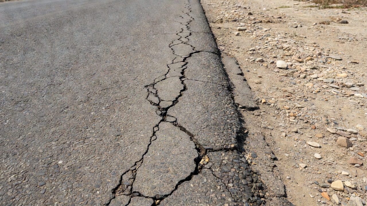
Edge cracking is a specific type of pavement distress officially defined in the Federal Highway Administration (FHWA) Long-Term Pavement Performance (LTPP) Distress Identification Manual (DIM) , Fifth Revised Edition, publication number FHWA-HRT-13-092. According to the manual, edge cracking is characterized as crescent-shaped cracks or fairly continuous cracks that intersect the pavement edge and are located within 0.6 meters (approximately 2 feet) of the pavement edge adjacent to the shoulder. This distress type applies exclusively to pavements that have unpaved shoulders — a critical distinction that separates edge cracking from other crack types that may appear in a similar location but on pavements with paved shoulders.
The LTPP Distress Identification Manual explicitly states: “Includes longitudinal cracks outside of the wheel path and within 0.6 m of the pavement edge.” This inclusion is important because it recognizes that edge cracking manifests in two morphological forms — the classic crescent-shaped cracks that curve and intersect the pavement edge (also referred to as cracking due to their distinctive half-moon pattern), and longitudinal-oriented cracks that run parallel to the pavement centerline but are confined to the outermost 0.6 m strip of the pavement surface. Both morphologies are classified under the same distress type because they share the same underlying causes and require the same repair strategies.
The location of edge cracking is specifically defined by the DIM. The crack pattern must be within 0.6 m (2 ft) of the pavement edge — the boundary between the traveled way and the shoulder. The crack or cracks must intersect the pavement edge — meaning they are physically connected to the edge of the paved surface, not isolated cracks that happen to be near the edge but do not reach it. The shoulder adjacent to the cracked edge must be unpaved — earthen, gravel, or grass, without a paved surface. If the shoulder is paved, the same crack would be classified as a non-wheelpath longitudinal crack (Type 4b) rather than edge cracking.
The unit of measurement for edge cracking, per the LTPP DIM, is meters of pavement edge affected at each severity level. The combined quantity of edge cracking cannot exceed the total length of the section being surveyed. This means that if a 100-meter section has edge cracking along 40 meters of its edge, the maximum possible recorded quantity is 40 meters, regardless of how many individual crack segments exist within that 40-meter stretch.
Edge cracking is classified as Distress Type ACP 3 in the LTPP DIM, and as Distress Type 07 in the ASTM D6433 Standard Practice for Roads and Parking Lots Pavement Condition Index Surveys. In the ASTM system, edge cracking is measured in linear feet rather than meters, but the same severity classification system applies: Low, Medium (Moderate), or High severity.
The importance of correctly identifying edge cracking lies in its diagnostic value — it indicates a specific set of structural and environmental deficiencies at the pavement edge that differ fundamentally from those causing other crack types. An inspector who correctly identifies edge cracking is immediately alerted to potential problems with shoulder support, edge drainage, or frost action that would not be indicated by longitudinal cracking in the wheelpath or by fatigue cracking. This diagnostic specificity makes proper distress identification essential for selecting the correct maintenance and repair strategy.
Causes of Edge Cracking
Edge cracking arises from a combination of structural, environmental, and traffic-related factors that concentrate stress at the pavement edge. Unlike distresses that occur primarily in the wheelpath (such as fatigue cracking), edge cracking is fundamentally a support-related failure — the pavement edge lacks the lateral confinement, vertical support, or drainage protection necessary to withstand the combination of traffic loads and environmental forces.
Lack of Lateral Support
The single most common cause of edge cracking is insufficient lateral support from the shoulder. In a properly functioning pavement system, the shoulder provides horizontal confinement that prevents the pavement structure from spreading outward under traffic loading. When the shoulder fails to provide this confinement — because it is too narrow, too steep, composed of erodible material, or poorly compacted — the pavement edge becomes a free edge with no lateral restraint.
The mechanics of lateral support failure are straightforward. When a vehicle tire passes near the pavement edge (within 0.3 to 0.6 m of the edge), the vertical load generates horizontal tensile stresses at the bottom of the asphalt layer. In the interior of the pavement, these tensile stresses are carried by the adjacent pavement structure. At the edge, however, there is no adjacent structure to carry these stresses — the unpaved shoulder provides negligible tensile resistance. The result is a concentration of tensile stress at the pavement edge that exceeds the tensile strength of the asphalt, causing cracks that initiate at the bottom of the asphalt layer and propagate upward to the surface.
Shoulder drop-off — a vertical or near-vertical difference in elevation between the pavement surface and the shoulder surface — exacerbates lateral support failure. When a vehicle tire drops off the pavement edge onto a lower shoulder surface, the impact loading on the pavement edge is significantly higher than normal rolling loads. This impact loading can cause instantaneous cracking of the pavement edge, particularly in older or more brittle asphalt mixtures. The FHWA publication “Best Practices for Pavement Edge Maintenance” (ROSA P, DOT 66489) identifies shoulder drop-off as a primary contributor to edge cracking and recommends prompt restoration of shoulder elevation to match the pavement surface.
Shoulder material shrinkage is another form of lateral support loss. Unpaved shoulders constructed with cohesive soils (silts and clays) undergo volume changes with moisture variation. During dry periods, the shoulder soil shrinks, pulling away from the pavement edge and creating a gap that eliminates lateral support. The gap also creates a preferential path for water infiltration, further weakening the base and subbase at the pavement edge. This shrinkage-induced edge cracking is particularly common in regions with distinct wet and dry seasons.
Poor Drainage
Poor drainage at the pavement edge is the second major cause of edge cracking. Water accumulation at the edge of the pavement structure initiates a cascade of deterioration mechanisms. When water collects in the base and subbase layers at the pavement edge — due to inadequate ditches, clogged drainage structures, or a high water table — the supporting capacity of these layers is dramatically reduced. Saturated granular materials lose 50% or more of their load-bearing capacity compared to dry conditions.
The base and subbase layers at the pavement edge are particularly vulnerable to drainage problems because they are exposed laterally through the unpaved shoulder. Water can enter these layers not only from the surface (through cracks or permeable pavement) but also laterally through the shoulder. Inadequate edge ditches that fail to collect and convey water away from the pavement structure allow water to pond against the pavement edge, saturating the base and subbase from the side.
Drainage-induced edge cracking follows a characteristic progression. First, water accumulates in the base and subbase at the pavement edge, saturating these layers and reducing their stiffness and strength. Second, under traffic loading, the saturated base and subbase deform, causing the overlying asphalt to settle and crack at the edge. Third, the cracks allow more water to enter the pavement structure, accelerating the deterioration. Fourth, the crack edges ravel and break up under traffic, widening the cracks into the characteristic crescent shape. Without drainage correction, this cycle continues until the pavement edge disintegrates completely.
Frost Action
Frost action is a major cause of edge cracking in cold climate regions, where seasonal freezing and thawing create conditions uniquely damaging to pavement edges. The mechanism involves three linked processes: frost heave (upward displacement of the pavement surface due to ice lens formation in the subgrade), spring thaw weakening (loss of subgrade strength when frozen ice lenses melt), and differential movement (uneven displacement between the pavement edge and the adjacent shoulder).
During freezing periods, water in the subgrade migrates toward the freezing front through capillary action, forming ice lenses — horizontal layers of pure ice that can be several centimeters thick. The formation of these ice lenses causes the ground surface to heave upward. Because the shoulder is typically more permeable and less compacted than the pavement structure, more water accumulates under the shoulder than under the pavement, causing greater frost heave at the shoulder than at the pavement interior. This differential frost heave between the pavement edge (less heave) and the shoulder (more heave) induces bending stresses in the asphalt layer at the pavement edge that can cause cracking.
During the spring thaw period, the ice lenses melt from the top down, releasing large quantities of water into the subgrade and base layers. The saturated subgrade at the pavement edge loses virtually all of its load-bearing capacity — in extreme cases, the California Bearing Ratio (CBR) of a thawing subgrade can drop to less than 20% of its summer value. Under traffic loading, the unsupported pavement edge settles and cracks, producing the characteristic edge cracking pattern.
The combination of differential frost heave in winter and spring thaw weakening makes edge cracking particularly severe in northern climates. Pavements in USDA Hardiness Zones 4 and colder (where minimum temperatures fall below -30°C) are at highest risk. Mitigation strategies include the use of frost-free granular base materials, installation of edge drains to remove spring thaw water, and ensuring adequate shoulder drainage to prevent water accumulation under the shoulder.
Traffic Encroachment
Traffic encroachment — vehicles operating closer to the pavement edge than the pavement was designed to accommodate — is a significant contributing factor to edge cracking. The edge of the pavement structure is typically the weakest part of the pavement cross-section because it lacks the lateral support and load distribution capacity of the interior pavement. When traffic repeatedly loads this weak edge, the asphalt layer fails in fatigue much sooner than it would in the interior of the lane.
Load proximity effects are critical. The stress in the subgrade at the pavement edge under a wheel load positioned at the edge is approximately 1.5 to 2.5 times higher than the stress under the same load positioned at the center of the lane. This stress concentration factor increases as the shoulder support deteriorates. A vehicle whose outer tire tracks consistently within 0.3 m of the pavement edge can effectively reduce the fatigue life of the pavement edge by a factor of 10 or more compared to the interior wheelpath.
Wide vehicles such as buses, trucks with wide axles, and agricultural equipment are particularly damaging to pavement edges because their tire paths frequently extend close to or beyond the pavement edge. On roads with narrow lane widths (less than 3.3 m), even passenger vehicles may encroach on the pavement edge, particularly on curves where the rear wheels track inside the front wheels.
Road geometry factors that increase traffic encroachment include: narrow lane widths (less than 3.3 m), tight curves (radius less than 100 m) where rear-wheel tracking shifts toward the pavement edge, absence of paved shoulders (which allows drivers to feel less constrained), and absence of edge line markings (which provide visual guidance to keep vehicles away from the edge).
FHWA LTPP Severity Classification
The FHWA LTPP Distress Identification Manual defines three severity levels for edge cracking, based on the degree of material breakup and loss along the affected pavement edge. These severity levels are applied during visual field surveys and directly influence the Pavement Condition Index (PCI) score calculated per ASTM D6433.
Low Severity is defined as cracks with no breakup or loss of material. At this severity level, the cracks are primarily cosmetic — they are visible on the pavement surface but no material has been dislodged from the crack edges. The crack width is typically less than 6 mm (1/4 inch), and the crack edges are intact and sound. The cracks may be single crescent-shaped cracks or short longitudinal segments, but they have not yet developed the raveled, broken edges that characterize higher severity levels. Low severity edge cracking is primarily a moisture infiltration concern — if left unsealed, water can enter the crack and begin damaging the base and subbase layers. At this stage, crack sealing is highly effective and cost-efficient, typically costing $0.50-$1.50 per linear foot.
Moderate Severity is defined as cracks with some breakup and loss of material for up to 10 percent of the length of the affected portion of the pavement. At this severity level, the crack edges have begun to deteriorate — aggregate particles are dislodged, and small pieces of the crack edge have broken away under traffic loading. The crack width typically ranges from 6 mm to 25 mm (1/4 to 1 inch), and the crack edges are rough and irregular. Moderate severity edge cracking represents the transition from a crack to a structural defect. The breakup of material along the crack edge creates stress concentrations that accelerate further cracking and raveling. At this stage, crack sealing may still be effective after cleaning and preparing the crack, but it is approaching the point where more extensive repairs will be needed.
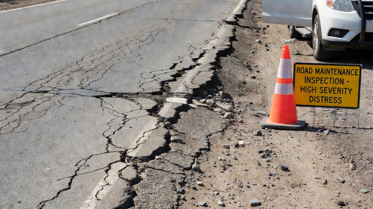
High Severity is defined as cracks with considerable breakup and loss of material for more than 10 percent of the length of the affected portion of the pavement. At this severity level, the pavement edge is actively disintegrating. The crack width typically exceeds 25 mm (1 inch), and significant portions of the crack edge have broken away, creating a pitted, raveled surface. Multiple interconnected cracks may be present, and loose material may be scattered along the pavement edge. High severity edge cracking represents a structural failure of the pavement edge that cannot be effectively repaired by crack sealing alone. At this stage, removal and replacement of the affected pavement section, combined with shoulder reconstruction and drainage improvement, is the appropriate repair strategy.
The severity classification system is designed to be applied in a binary fashion at graded intervals along the pavement edge. The inspector walks or drives along the pavement edge, noting the beginning and end points of each severity level. For example, a 100-meter section might have 30 meters of low severity cracking, 20 meters of moderate severity, 10 meters of high severity, and 40 meters with no cracking. The total of all severity levels cannot exceed the total section length (100 meters in this example).
The LTPP DIM explicitly states that when edge cracking and fatigue or block cracking exist and overlap in the same area, both should be rated. This means that an area near the pavement edge that exhibits both edge cracking and fatigue cracking (alligator pattern) should be recorded as edge cracking (in linear meters) and also as fatigue cracking (in square meters). This dual-rating rule is important for accurate PCI calculation, as each distress type contributes independently to the deduct value.
Differentiation from Longitudinal Cracking
Distinguishing edge cracking from longitudinal cracking is one of the most important — and potentially confusing — aspects of pavement distress identification. Both crack types can appear as linear cracks running approximately parallel to the pavement centerline, but they differ fundamentally in location, morphology, applicable shoulder conditions, causal mechanisms, and repair strategies.
Location criteria are the primary differentiating factor. Edge cracking is specifically defined as cracks occurring within 0.6 m (2 ft) of the pavement edge adjacent to the shoulder, that intersect the pavement edge. Longitudinal cracking can occur anywhere in the lane — in the wheelpath (Type 4a), outside the wheelpath (Type 4b), or anywhere else parallel to the pavement centerline. A crack running parallel to the centerline at 0.8 m from the pavement edge is longitudinal cracking, not edge cracking, because it falls outside the 0.6 m zone. A crack at 0.4 m from the edge but that does not intersect the edge is also longitudinal cracking.
Morphology differences are also significant. Edge cracking is characterized by crescent-shaped cracks that curve toward and intersect the pavement edge. These crescent or half-moon shapes are highly distinctive and are not seen in longitudinal cracking. Where the crack follows a fairly continuous longitudinal path within 0.6 m of the edge, the edge cracking may look similar to longitudinal cracking, but the crescent-shaped segments and the connection to the pavement edge confirm it as edge cracking.
Shoulder condition is a critical differentiating factor. Edge cracking applies only to pavements with unpaved shoulders. If the shoulder is paved with asphalt or concrete, the same morphological crack pattern within 0.6 m of the edge is classified as non-wheelpath longitudinal cracking (Type 4b) , not edge cracking. This distinction exists because the paved shoulder provides lateral support that fundamentally changes the causal mechanism — a crack in this location on a paved-shoulder road is more likely caused by fatigue or reflective cracking than by lateral support failure.
Causal mechanism differences are important for selecting appropriate repair strategies. Edge cracking is caused by lack of lateral support, shoulder drop-off, poor edge drainage, or frost action at the edge. Longitudinal cracking is caused by fatigue loading, poor joint construction, reflective cracking from underlying layers, or top-down cracking from thermal stresses. A repair strategy appropriate for one may be ineffective for the other.
Severity classification systems differ between the two crack types. Edge cracking severity is based on the percentage of crack length with breakup and loss of material (none for Low, up to 10% for Moderate, more than 10% for High). Longitudinal cracking severity is based on crack width (≤ 6 mm for Low, 6-19 mm for Moderate, > 19 mm for High) and the presence of adjacent random cracking.
Measurement methods also differ. Edge cracking is measured in linear meters of pavement edge affected at each severity level, with a maximum equal to the section length. Longitudinal cracking is measured in linear meters of individual crack length at each severity level, with each crack measured separately and summed within the section.
Characteristic
Edge Cracking (ACP 3)
Longitudinal Cracking (ACP 4)
Location
Within 0.6 m of pavement edge
Anywhere in the lane
Edge intersection
Must intersect pavement edge
Not required
Shoulder type
Unpaved shoulders only
Any shoulder type
Typical morphology
Crescent-shaped, curved, intersecting edge
Straight, parallel to centerline
Primary cause
Lack of lateral support, drainage, frost
Fatigue, joint construction, reflection
Severity basis
Material breakup and loss (%)
Crack width (mm)
Measurement unit
Meters of affected edge
Meters of crack length
Deduct value impact
Varies by severity and extent
Varies by severity and extent
The practical implication for pavement inspectors is clear: when a crack is observed near the pavement edge, the inspector must determine whether the crack intersects the edge, whether the shoulder is unpaved, and whether the crack falls within the 0.6 m zone. Only when all three conditions are satisfied should it be recorded as edge cracking. In all other cases, it should be recorded as the appropriate type of longitudinal cracking.
Measurement of Edge Cracking
The measurement of edge cracking follows standardized procedures defined in the LTPP Distress Identification Manual and ASTM D6433. Accurate measurement is essential for calculating the Pavement Condition Index (PCI) and for tracking the progression of edge deterioration over time.
Measurement protocol per FHWA LTPP DIM: The inspector records the length in meters of pavement edge affected at each severity level. The combined quantity of edge cracking cannot exceed the length of the section being surveyed. For example, in a 100-meter pavement section, the inspector might record: Low severity edge cracking = 30 m, Moderate severity = 15 m, High severity = 5 m, No cracking = 50 m. The total of all severity levels (30 + 15 + 5 = 50 m) would not exceed the section length of 100 m.
Measurement protocol per ASTM D6433: For Pavement Condition Index surveys, edge cracking (Distress Type 07) is measured in linear feet at each severity level (Low, Medium, High). The same rule applies — the total measured length cannot exceed the sample unit length. The standard survey method defines the sample unit as approximately 2,500 square feet (232 square meters) for asphalt concrete roads, typically 100 feet (30.5 m) long by one lane width.
Distinguishing severity segments along the pavement edge: The inspector must determine where each severity level begins and ends along the pavement edge. The transition between severity levels is not always sharp — there may be a gradual progression from low to moderate severity. In such cases, the DIM recommends rating the entire affected portion at the highest severity level present if the severity levels cannot be clearly distinguished. For example, if a 20-meter stretch of pavement edge has low severity cracking along its entire length but the last 3 meters show moderate severity breakup, the entire 20-meter stretch should be rated at moderate severity (the higher level) if the transition is gradual and the severity levels cannot be cleanly separated.
Dual rating rule: When edge cracking and fatigue or block cracking exist and overlap in the same area, both should be rated. This means the inspector records the linear meters of edge cracking AND the square meters of fatigue or block cracking in the overlapping area. The dual rating is necessary because each distress type contributes independently to the PCI deduct value calculation.
Field measurement techniques: The inspector can measure edge cracking using a measuring wheel, tape measure, or by pacing (with calibration). For automated surveys using pavement imaging vehicles, edge cracking is identified and measured using image analysis algorithms that detect crack patterns within the defined edge zone. The automated method must be capable of reliably distinguishing edge cracks from longitudinal cracks based on the 0.6 m edge zone criterion and the crack-edge intersection requirement.
Quality assurance: The LTPP DIM requires that measurements be recorded to the nearest 0.1 m (or 0.5 ft in ASTM system). The survey map sheets should show the crack configuration, location relative to the pavement edge, and severity level boundaries. Photographic documentation is recommended for QA/QC purposes and for tracking changes over time.
Implications for Pavement Structure
Edge cracking has significant implications for the structural integrity and service life of the pavement. Understanding these implications is essential for prioritizing repairs, allocating maintenance budgets, and designing preventive measures for new construction.
Structural weakening of the pavement edge: Edge cracking represents a localized structural failure of the pavement at its lateral boundary. The crack itself reduces the effective thickness of the asphalt layer at the edge, and the associated material breakup and loss further reduce the structural capacity of the affected area. In high severity edge cracking, the pavement edge can lose 50% or more of its effective structural cross-section within the cracked zone.
Moisture infiltration acceleration: Every crack is a pathway for water to enter the pavement structure. Edge cracks are particularly problematic because they are located at the pavement edge — the same location where water naturally collects due to inadequate drainage. Water entering through edge cracks saturates the base and subbase layers, reducing their load-bearing capacity and accelerating the deterioration of the entire pavement structure. The combination of edge cracking and poor drainage creates a self-reinforcing deterioration cycle — cracks allow water in, water weakens the support, weakened support causes more cracking.
Progression to other distress types: Untreated edge cracking frequently progresses to more severe distress types. The most common progression is from edge cracking to raveling — the loss of aggregate from the pavement surface at the crack edge. As raveling progresses, the crack widens and deepens, eventually forming a pothole at the pavement edge. Edge cracking can also progress to edge failure — the complete disintegration of the pavement edge, creating a rough, uneven surface that is hazardous to traffic and allows even more water infiltration.
Load transfer reduction: The pavement edge is the part of the pavement system that transfers loads from the pavement structure to the shoulder and, ultimately, to the subgrade. Edge cracking disrupts this load transfer mechanism, concentrating stress at the crack tip and accelerating the progression of the crack both longitudinally (along the pavement edge) and transversely (toward the center of the lane).
Safety hazards: Edge cracking creates safety hazards for road users. The cracks themselves can cause vehicle handling issues (particularly for motorcycles and bicycles), and the associated breakup and loss of material creates loose aggregate on the pavement surface that can reduce skid resistance. In severe cases, edge cracking can produce a drop-off between the pavement surface and the shoulder, creating a tripping hazard for pedestrians and a vehicle control hazard for drivers who wander off the pavement edge.
Drainage system impact: Edge cracking is both a symptom and a cause of drainage system problems. The cracks allow water to bypass the edge drainage system, entering the pavement structure directly. Over time, this can erode the base and subbase materials, carrying fines into the drainage system and clogging edge drains, ditches, and culverts. The resulting drainage failure then accelerates the deterioration of the pavement edge, creating a worsening cycle.
Accelerated pavement deterioration: Research has shown that pavements with untreated edge cracking deteriorate significantly faster than those without edge cracking. A study by the Texas Transportation Institute found that edge cracking can reduce pavement service life by 3 to 7 years depending on the severity of the cracking, the quality of the shoulder support, and the effectiveness of the drainage system. Early intervention — crack sealing at the low severity level — can restore the pavement to near-original condition and prevent further deterioration. Delaying repair until moderate or high severity requires more extensive and expensive repairs and may permanently reduce the structural capacity of the pavement.
The structural implications of edge cracking underscore the importance of including edge cracking in pavement condition surveys and incorporating it into pavement management system decision-making. Ignoring edge cracking because it occurs at the pavement edge rather than in the wheelpath is a mistake — edge cracking is a warning signal that the pavement structure is failing at its lateral boundary, and if left unaddressed, the failure will propagate inward and reduce the service life of the entire pavement.
Detection of Edge Cracking by Artificial Intelligence
The application of artificial intelligence (AI) and computer vision to pavement distress detection has advanced rapidly in recent years, and edge cracking presents specific challenges and opportunities for automated detection. AI-based detection systems can significantly improve the speed, consistency, and objectivity of edge cracking surveys compared to manual visual inspection.
Detection challenges specific to edge cracking: Edge cracking is one of the more difficult distress types for AI systems to detect reliably, for several reasons. The crack morphology is variable — crescent-shaped cracks are morphologically different from longitudinal edge cracks, and an AI model must recognize both as the same distress type. The 0.6 m edge zone must be precisely defined in the image coordinate system, requiring accurate knowledge of the camera position relative to the pavement edge. The intersection with the pavement edge — a defining characteristic of edge cracking — requires the AI to recognize the boundary between the paved surface and the unpaved shoulder, which can be visually indistinct in some conditions. The variable lighting conditions at the pavement edge (shadows from adjacent vegetation, varying shoulder color and texture) can confuse AI models trained on interior pavement images.
Image processing techniques for edge crack detection: Modern AI-based pavement distress detection typically uses convolutional neural networks (CNNs) or transformer-based architectures that have been trained on large datasets of annotated pavement images. The detection pipeline generally involves: image acquisition (from survey vehicles, drones, or smartphones), image pre-processing (normalization, enhancement, geometric correction), crack segmentation (pixel-level identification of crack pixels), crack classification (assignment of each crack segment to a distress type), and crack quantification (measurement of crack length and severity).
CNN-based approaches use deep learning architectures such as U-Net, ResNet, YOLO (You Only Look Once), and Mask R-CNN for crack detection and segmentation. For edge cracking specifically, the AI model must incorporate spatial context information — it must know where the pavement edge is in the image to determine whether a crack falls within the 0.6 m zone. This requires either explicit edge detection (identifying the pavement-shoulder boundary) or implicit edge learning (training the model on images where edge cracks have been annotated along with their spatial location relative to the edge).
Automated severity classification using AI requires the model to assess material breakup and loss along the crack edge. This is more complex than simple crack detection, as it requires the AI to distinguish between a clean crack edge (low severity) and a raveled, broken crack edge (moderate or high severity). Deep learning models trained on severity-annotated datasets can achieve this distinction with accuracy rates exceeding 85% for low vs. high severity, with moderate severity being the most difficult to classify reliably.
Light Gradient Boosting Machine (LightGBM) approaches: Research published in the Journal of Soft Computing in Civil Engineering (2023) demonstrated that feature-based machine learning methods using steerable filters and projection integrals in combination with LightGBM classifiers can achieve accuracy rates exceeding 96% for pavement crack pattern recognition, including identification of cracks in the edge zone. These methods extract hand-crafted features from pavement images and use them to train the LightGBM classifier. The advantage of this approach over deep learning is that it requires less training data and computational resources, making it suitable for smaller-scale pavement management applications.
Data requirements for AI edge crack detection: Training an AI model for edge crack detection requires a large, diverse, and annotated dataset. Each training image must be annotated at the pixel level or object level with the crack type (edge crack vs. other crack types), severity level (low, moderate, high), and spatial relationship to the pavement edge. The dataset must include examples of edge cracking across a range of conditions: different pavement types, shoulder types, climate zones, lighting conditions, and severity levels. Public datasets such as the LTPP database, the CrackTree200 dataset, and the GAPs (German Asphalt Pavement Distress) dataset provide some edge crack images, but these datasets are generally small relative to the needs of deep learning models.
Integration with GIS and pavement management systems: AI-detected edge cracking data can be integrated with geographic information systems (GIS) and pavement management systems (PMS) for network-level analysis. The detected cracks are georeferenced (typically using GPS coordinates from the survey vehicle), allowing the PMS to track edge cracking progression over time, correlate edge cracking with other pavement data (traffic volume, pavement age, shoulder type, drainage characteristics), and prioritize maintenance interventions based on the severity and extent of edge cracking across the network.
Automated detection systems for edge cracking are still evolving, but they offer the potential for dramatically increased survey productivity (thousands of lane-kilometers per day versus a few kilometers per day for manual walking surveys), consistent classification (eliminating inter-inspector variability), and objective data for pavement management decision-making.
Edge Support and Drainage Solutions
Effective mitigation of edge cracking requires addressing the root causes — inadequate lateral support, poor drainage, frost action, and traffic encroachment. The most successful repair strategies combine shoulder restoration (providing lateral confinement), drainage improvement (removing water from the pavement edge), and structural reinforcement (strengthening the pavement edge against traffic loads).
Shoulder Restoration and Edge Support
Restoring adequate lateral support is the first priority in edge cracking repair. The shoulder must provide confinement that prevents the pavement structure from spreading outward under traffic loading. For low to moderate severity edge cracking without significant structural damage, shoulder restoration may be sufficient to arrest further deterioration.
Shoulder widening adds material to the unpaved shoulder to increase its width and provide a larger bearing area for lateral support. The minimum shoulder width recommended for adequate lateral support is 1.5 m (5 ft) , with wider shoulders (2.4-3.0 m) preferred for higher-traffic roads. The added shoulder material should be compacted to at least 95% of maximum dry density (per AASHTO T99 or T180) to ensure it provides effective lateral confinement.
Shoulder reshaping restores the shoulder cross-slope to promote drainage away from the pavement edge. The recommended shoulder cross-slope is 4-6% (4-6 cm per meter), which is steeper than the typical pavement cross-slope of 1.5-2.5%. This steeper slope ensures that water drains off the shoulder surface rather than ponding against the pavement edge.
Shoulder material selection is critical for long-term performance. The ideal shoulder material is a granular material with low plasticity (Plasticity Index < 6), high friction angle (> 35°), and good drainage characteristics. Cohesive soils (silts and clays) should be avoided for shoulder construction because they shrink and swell with moisture changes, creating gaps at the pavement edge and providing inconsistent lateral support.
Geogrid Stabilization for Shoulder Reinforcement
Geogrid stabilization has emerged as a highly effective technique for reinforcing pavement shoulders and preventing edge cracking. Geogrids are polymer grid structures placed within the shoulder aggregate layers to provide mechanical interlock and confinement.
Mechanism of geogrid stabilization: The geogrid interlocks with the shoulder aggregate through its apertures, creating a mechanically stabilized layer that has higher tensile strength and stiffness than the un reinforced aggregate. The geogrid confines the aggregate laterally, preventing the outward spreading that leads to edge cracking. The stabilized shoulder provides continuous, uniform lateral support to the pavement edge, maintaining this support even under varying moisture conditions.
Tensar geogrid systems for shoulder stabilization use biaxial or triaxial geogrids with aperture sizes designed to interlock with the specific aggregate gradation used in the shoulder. The geogrid is placed at the base of the shoulder aggregate layer, typically 150-300 mm below the shoulder surface. The stabilized shoulder layer acts as a semi-rigid lateral support system for the pavement edge, distributing traffic loads over a wider area and reducing stress concentrations at the pavement edge.
3D geocell systems (such as Presto Geosystems GEOWEB system) provide a three-dimensional confinement system for shoulder stabilization. The geocell is a three-dimensional, honeycomb-like structure that is filled with aggregate, creating a stiff, self-contained layer that provides exceptional lateral support. Field studies have demonstrated that geocell-stabilized shoulders reduce edge maintenance by a factor of 3 or more compared to unstabilized shoulders.
Drainage Solutions
Improving edge drainage is the second critical component of edge cracking mitigation. Without effective drainage, water will continue to accumulate at the pavement edge, weakening the base and subbase layers and driving the deterioration cycle.
Edge ditches are the primary drainage system for pavement edges. The ditch must be deep enough to keep the water table at least 0.6 m below the pavement surface, and wide enough to convey the design storm runoff without overtopping. Vegetated ditches require periodic cleaning and reshaping to maintain their capacity.
Subsurface edge drains (pipe drains) are installed parallel to the pavement edge, typically at the base of the pavement structure, to collect and remove water from the base and subbase layers. The drain pipe is wrapped in a geotextile filter fabric to prevent clogging and placed in a trench with permeable backfill (typically clean, washed gravel). The drain outlet must be properly graded to discharge to a suitable outlet without endangering the pavement structure.
Shoulder underdrains are a specialized drainage system for problem areas where edge cracking is caused by poor subsurface drainage. The underdrain consists of a perforated pipe in a gravel-filled trench, installed longitudinally along the pavement edge, with lateral outlets spaced at regular intervals. The underdrain intercepts groundwater flow before it reaches the pavement structure and removes it through the outlet system.
Drainage maintenance is essential for long-term performance. Ditches must be cleaned of sediment and vegetation annually, or more frequently in areas with high sediment loads. Outlet pipes must be inspected for blockage and cleaned as needed. Drainage structures (culverts, catch basins) must be inspected and maintained to ensure they continue to function at their design capacity.
Crack Sealing at the Pavement Edge
Crack sealing is an effective preventive maintenance treatment for low severity edge cracking. The goal of crack sealing is to prevent water infiltration through the crack, slowing the deterioration cycle and extending the service life of the pavement.
Sealant selection for edge cracks should consider the crack width and the climatic conditions at the site. For narrow cracks (less than 6 mm), a low-viscosity sealant may be appropriate. For wider cracks (6-25 mm), a high-elasticity sealant that can accommodate crack movement is required. Hot-applied rubberized asphalt sealants are the most commonly used type for edge crack sealing.
Crack preparation is critical for sealing success. The crack must be cleaned of debris, vegetation, and loose material using compressed air, a wire brush, or a router. The crack walls must be dry and at a temperature above 4°C (40°F) for proper sealant adhesion. In cold climates, the crack may need to be heated before sealant application to ensure proper bonding.
Sealant application fills the crack with sealant, leaving a slight overband (1-2 mm above the pavement surface) to allow for sealant shrinkage and to ensure complete filling of irregular crack walls. The sealed crack must be protected from traffic until the sealant has cured sufficiently.
Full-Depth Edge Repair
For high severity edge cracking with considerable breakup and loss of material, full-depth repair is required. The repair involves removing the damaged pavement and shoulder material, reconstructing the edge support system, and replacing the pavement structure.
Removal area should extend at least 0.3 m beyond the visible crack damage on both sides and be at least 0.6 m wide. The removal depth should be full depth of the asphalt layer. The base and subbase layers should be inspected and replaced if damaged by water infiltration.
Reconstruction involves placing and compacting new base material to the proper grade and cross-slope, placing a tack coat on the vertical faces of the existing pavement (to ensure bond between old and new material), and placing and compacting new HMA in lifts not exceeding 75 mm (3 inches) for each lift.
Shoulder restoration is performed concurrently with the pavement repair. The shoulder is graded to the proper cross-slope, compacted, and finished to match the elevation of the adjacent pavement edge. If geogrid stabilization is to be used, the geogrid is placed at the appropriate depth within the shoulder aggregate.
Drainage correction is performed as part of the repair. The edge ditch is cleaned, reshaped, or reconstructed as needed. Subsurface drains are installed if the site has a history of drainage problems. The repaired section is monitored for the first 12 months to ensure the edge cracking does not recur.
The selection of the appropriate repair strategy depends on the severity and extent of edge cracking, the condition of the shoulder, the drainage characteristics of the site, the traffic level, and the available budget. A cost-benefit analysis should consider not only the initial repair cost but also the expected service life extension and the avoided future maintenance costs. In most cases, early intervention (crack sealing at low severity) is the most cost-effective strategy, with benefit-cost ratios of 5:1 or higher compared to delayed repair at moderate or high severity.
Frequently Asked Questions
Per the FHWA LTPP Distress Identification Manual (Fifth Revised Edition, FHWA-HRT-13-092), edge cracking is defined as crescent-shaped cracks or fairly continuous cracks which intersect the pavement edge and are located within 0.6 m of the pavement edge adjacent to the shoulder. It applies only to pavements with unpaved shoulders. The distress includes longitudinal cracks outside of the wheel path and within 0.6 m of the pavement edge. Edge cracking is recorded in meters of pavement edge affected at each severity level, and the combined quantity of edge cracking cannot exceed the length of the section.
The primary causes of edge cracking include: lack of lateral support from the shoulder (insufficient shoulder width, shoulder drop-off, or shoulder material shrinkage), poor drainage that weakens the base and subbase layers at the pavement edge, frost action in cold climates where freeze-thaw cycles cause non-uniform soil heave and induce bending stresses in the asphalt, traffic encroachment where vehicles repeatedly load the unsupported pavement edge, and erosion of shoulder material. The root cause is almost always inadequate structural support at the pavement edge relative to the applied loads.
The FHWA LTPP DIM defines three severity levels for edge cracking. Low severity: cracks with no breakup or loss of material. Moderate severity: cracks with some breakup and loss of material for up to 10 percent of the length of the affected portion of the pavement. High severity: cracks with considerable breakup and loss of material for more than 10 percent of the length of the affected portion of the pavement. The measurement unit is meters of pavement edge affected at each severity level.
Edge cracking differs from longitudinal cracking in several key ways. Edge cracking is specifically defined as cracks within 0.6 m of the pavement edge adjacent to the shoulder, it applies only to pavements with unpaved shoulders, and it is characterized by crescent-shaped cracks that intersect the pavement edge. Longitudinal cracking runs parallel to the pavement centerline and can occur anywhere in the lane — in the wheelpath (Type 4a) or outside the wheelpath (Type 4b). Edge cracking is measured in linear meters of affected pavement edge, while longitudinal cracking is measured as individual crack lengths. Edge cracking is caused primarily by lack of lateral support, whereas longitudinal cracking is typically related to fatigue, poor joint construction, or reflective cracking.
Per FHWA LTPP protocols, edge cracking is measured by recording the length in meters of pavement edge affected at each severity level. The combined quantity of edge cracking cannot exceed the length of the section. When edge cracking and fatigue or block cracking exist and overlap in the same area, both should be rated separately. In ASTM D6433 PCI surveys, edge cracking (Distress Type 07) is measured in linear feet at Low, Medium, or High severity. The inspector records the total length of edge affected by cracking, distinguishing between severity levels when different portions of the edge exhibit different degrees of deterioration.
Effective maintenance strategies for edge cracking depend on the severity and extent of the damage. For low severity cracks, crack sealing prevents moisture infiltration and further raveling. For moderate severity, crack sealing combined with shoulder restoration (adding shoulder material and ensuring adequate lateral support) addresses the root cause. For high severity with considerable breakup and loss of material, removal and replacement of the affected pavement edge combined with shoulder reconstruction is required. Long-term preventive measures include: ensuring the shoulder has adequate width and compaction, improving edge drainage through ditches and subdrains, using geogrid stabilization for shoulder reinforcement, and designing pavement edges with sufficient structural capacity for anticipated traffic loads.
No. Per the FHWA LTPP Distress Identification Manual, edge cracking applies only to pavements with unpaved shoulders. On pavements with paved shoulders, cracks in the same location (within 0.6 m of the pavement edge) are classified as longitudinal cracking (non-wheelpath) rather than edge cracking. This distinction is important because the causes and repair strategies differ significantly between paved and unpaved shoulder conditions. The presence of a paved shoulder provides lateral support that prevents the development of edge cracking as a distinct distress type.
Frost action is a significant cause of edge cracking in cold climate regions. During freeze-thaw cycles, water in the subgrade and base layers freezes and expands, causing non-uniform frost heave. This frost heave is typically more severe at the pavement edge where the shoulder (often more permeable and less compacted) allows greater water accumulation. The upward heave lifts the pavement edge and induces bending stresses in the asphalt layer that can result in cracking. During spring thaw, the saturated subgrade loses supporting strength, further exacerbating edge cracking under traffic loading. The combination of differential frost heave and spring thaw weakening makes edge cracking particularly problematic in northern climates.
Need Professional Pavement Edge Inspection?
TarmacView provides expert pavement condition assessments including edge cracking detection, severity classification, and airport pavement consulting with ICAO and FHWA-compliant inspection protocols.
Longitudinal Cracking in Asphalt and Concrete Pavements
Longitudinal cracks run parallel to the pavement centerline or direction of travel. Causes include poor construction joint bonding, reflective cracking from und...
Transverse Cracking in Asphalt and Concrete Pavements
Transverse cracks run perpendicular to the pavement centerline, most commonly caused by thermal contraction at low temperatures or reflective cracking from unde...
Alligator cracking — also called fatigue cracking — is an interconnected crack pattern resembling alligator skin that indicates structural failure of the asphal...
30 min read
pavement-defects
Asphalt Pavement
+3
Cookie Consent We use cookies to enhance your browsing experience and analyze our traffic. See our privacy policy.