Edge drains are longitudinal subsurface drains installed along pavement edges to intercept and remove water from the pavement structure, preventing water-related distress such as pumping, faulting, and freeze-thaw damage. Edge drain condition assessment is a critical component of comprehensive pavement drainage inspection for airport and highway pavements.
Pavement Edge Drain — Longitudinal Subsurface Drainage System for Water Removal
A pavement edge drain is a longitudinal subsurface drainage system installed along the edge of a pavement structure to intercept, collect, and remove water that infiltrates through the pavement surface, joints, cracks, and pavement-shoulder interfaces. Edge drains consist of a perforated collector pipe placed in a narrow trench lined with geotextile filter fabric and backfilled with clean permeable aggregate. They serve as the terminal collection and conveyance element of the pavement subsurface drainage system, collecting water that migrates laterally through the permeable base layer and discharging it through outlet pipes to roadside ditches or storm drain systems.
Edge drains are distinguished from general underdrains by their specific function and location: they are installed longitudinally along the pavement edge, dedicated to collecting water from the pavement structure itself, rather than intercepting groundwater from adjacent terrain. The terms edge drain, longitudinal drain, collector drain, and pavement edge underdrain are used interchangeably in FAA and FHWA guidance documents.
Definition and Purpose
The fundamental purpose of pavement edge drains is to remove free gravitational water from the pavement structural section within a specified time frame after a rainfall event. Water enters pavements through multiple pathways: infiltration through surface cracks and joints (the largest source, accounting for up to 40% of rainfall per Minnesota DOT studies), lateral flow from shoulders and adjacent terrain, upward capillary rise from a high water table, and vapor condensation beneath impermeable surfaces. Once inside, this water becomes trapped if no drainage path exists.
Per the FAA Advisory Circular 150/5320-5D (Airport Drainage Design), Appendix G, the specific purposes of subsurface pavement drainage — including edge drains — are to:
Remove surface infiltration water that enters through cracks, joints, pavement-shoulder interfaces, and pores in the pavement surface
Intercept and drain water generated by freeze-thaw action
Prevent buildup of hydrostatic water pressure beneath pavements
Control groundwater where the water table is high
Prevent water from being trapped between impermeable layers
The FAA requires subsurface drainage for all airport pavements except those in non-frost areas with subgrade permeability greater than 6 m/day (20 ft/day), or flexible pavements in non-frost areas with total structure thickness less than 200 mm (8 inches) above the subgrade. For rigid pavements, special care is required to ensure water drains rapidly from beneath the slab regardless of these exemption criteria. When a drainage layer (permeable base) is present, collector edge drains are mandatory.
The ICAO Aerodrome Design Manual (Doc 9157, Part 3 — Pavements, 3rd Edition, 2022) discusses pavement drainage in Appendix 6 (Pavement Operations and Maintenance Related Guidance), noting that drainage is critical to pavement life. ICAO refers users to State practices — primarily FAA guidance in the United States — for detailed design specifications.
The AASHTO Guide for Design of Pavement Structures defines drainage quality based on time-to-drain: excellent drainage removes 50% of free water within 2 hours, good within 1 day, fair within 1 week, and poor within 1 month. Pavements with excellent drainage experience dramatically longer service lives than those with poor drainage, as the duration of saturation — and therefore the opportunity for moisture-related damage — is minimized.
Edge Drain Design Standards
Edge drain design is governed by FAA AC 150/5320-5D, Appendix G (Design of Subsurface Pavement Drainage Systems) and FAA AC 150/5370-10H, Item D-705 (Pipe Underdrains for Airports). These documents provide comprehensive specifications for all components of the edge drain system.
When Edge Drains Are Required
FAA Appendix G specifies mandatory subsurface drainage for:
All pavements in frost areas
All pavements where subgrade permeability is less than 6 m/day (20 ft/day)
All pavements with a drainage layer (permeable base) — edge drains are mandatory
Rigid pavements regardless of exemptions (due to the critical need for water removal beneath slabs)
Edge drains are not required only for:
Pavements in non-frost areas with subgrade permeability exceeding 6 m/day (vertical drainage is sufficient through permeable subgrade)
Flexible pavements in non-frost areas with total thickness above subgrade less than 200 mm (8 in)
Pipe Types and Specifications
Per FAA AC 150/5320-5D §G-6.2.2, collector pipe materials include:
Pipe Type
Specification
Typical Application
Corrugated Polyethylene (CPE)
AASHTO M 252
Standard edge drain — flexible, economical
PVC (smooth, rigid)
AASHTO M 278, Class PS46
Where higher rigidity is required
ABS (acrylonitrile butadiene styrene)
Flexible/perforated
Special applications
Geocomposite edge drains (strip drains)
FAA modification required
Only for pavements without a drainage layer
All plastic pipe installed under airfield pavements must comply with Item D-701 (Pipe for Storm Drains and Culverts) in AC 150/5370-10.
Pipe Size
The minimum diameter for all collector edge drains is 150 mm (6 inches) per FAA §G-6.2.3. Larger pipe sizes are computed using Manning’s equation for full-flowing circular pipe:
English units: Q = (1.486/n) × A × (d/4)^(2/3) × s^(1/2)
Where n is the roughness coefficient: 0.013 for smooth-wall plastic or concrete pipe, 0.024 for corrugated metal pipe. A 150 mm (6 in) diameter is satisfactory for most installations except long intercepting lines or severe groundwater conditions where larger diameters are required.
Slope Requirements
The minimum slope for subdrains is 0.15% per FAA §G-6.2.1. However, Caltrans research has found that edge drains become ineffective when the longitudinal collector slope is less than 0.2%, and slopes below 1% are prone to sediment accumulation at sags. The FHWA recommends minimum 1% slope to avoid sediment deposition and to facilitate self-cleaning flow velocities.
Trench Dimensions
FAA §G-6.2.2 specifies:
Trench width: minimum 150 mm (6 in) clearance on each side of the pipe
Trench depth: minimum 300 mm (12 in) from the top of pavement subgrade to pipe centerline, plus 80 mm (3 in) clearance beneath the pipe
In frost areas with F3/F4 soils: place below frost depth if possible; if frost depth exceeds 1.2 m (4 ft), the pipe need not be deeper than 1.2 m (4 ft) from the bottom of the drainage layer
Trench side slopes in frost areas: 1V:10H within the frost depth zone at the pavement edge; 1V:4H outside traffic areas
Outlet Spacing
Per FAA §G-6.4.1, outlet spacing is a critical design parameter:
Lateral outlet pipes at intervals of 90 to 150 m (300 to 500 ft) along edge drains
Additional outlets at the low point of all vertical curves
Outlet pipe placed at approximately 45° angle from the direction of flow in the collector drain
Recommended slope from edge drain to outlet structure: 3%
Invert of outlet pipe: minimum 150 mm (6 in) above the 2-year design flow in the ditch
Dual outlet system recommended to allow flushing sections of collector drain
Outlet pipes must have the same diameter as collector drains (for pipe drains); 102-152 mm (4-6 in) diameter for geocomposite drains
Flow capacity of outlets must be greater than that of collector drains
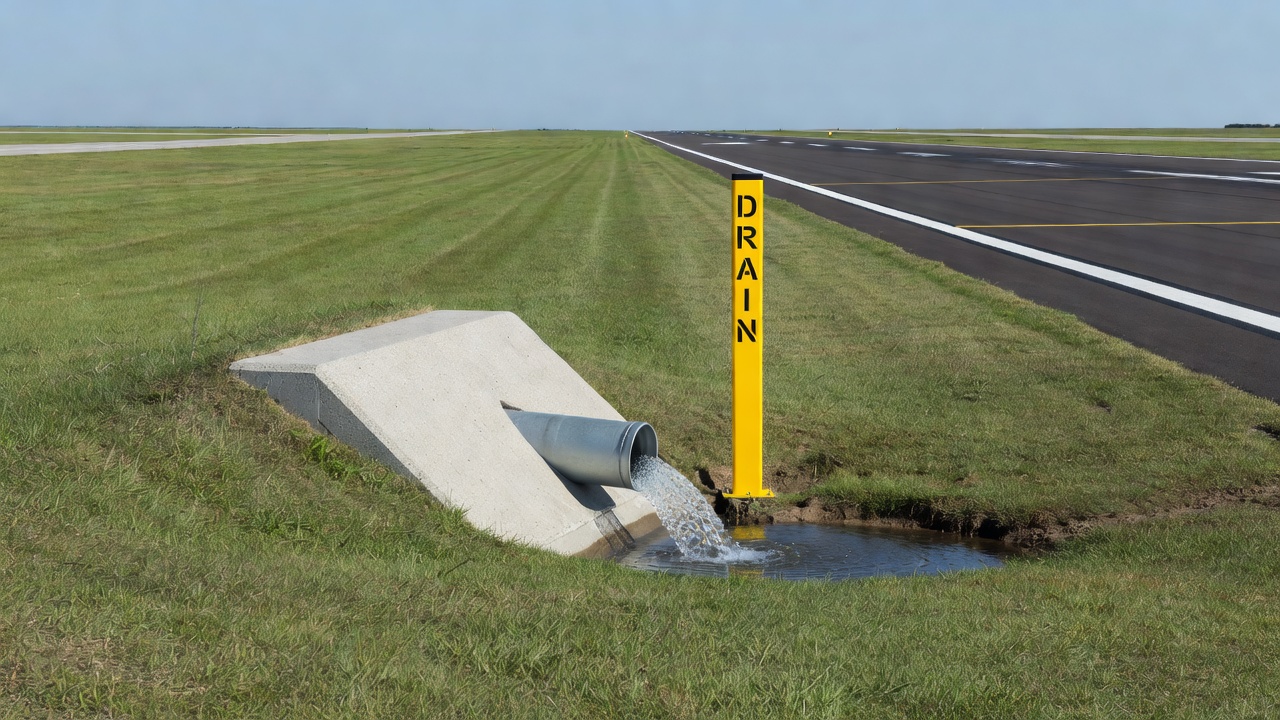
Outlet Structures
Outlet structures require:
Concrete headwall flush with the slope to not impede mowing
Easily removable rodent screens at the pipe outlet (required per FAA)
Reference markers for locating outlets during maintenance (painted arrows on shoulder, reflector disks, signs)
Dual outlet entrances to allow video inspection equipment and cleaning equipment to access the system
Manhole/Observation Spacing
Manholes on subgrade pipe drains: maximum 300 m (1,000 ft) intervals
Flushing riser between manholes and at dead ends
Manholes at principal junction points
Geotextile Wrap Specifications
The geotextile wrap around the edge drain trench is a critical component that prevents migration of fine soil particles from the adjacent subgrade into the aggregate backfill. Without proper geotextile filtration, the aggregate void spaces would progressively fill with fines, reducing drainage capacity and ultimately clogging the system entirely.
Geotextile for Edge Drain Trench Filter
Per FAA AC 150/5320-5D §G-2.7.2 and §G-6.3.2:
Nonwoven needle punch fabric (standard type for drainage applications)
AOS ≤ 0.212 mm (Apparent Opening Size) — this is the most critical specification, ensuring that the geotextile retains soil particles while allowing water passage
Geotextile fabric should NEVER be placed between the drainage layer and the edge drain — this would create a hydraulic barrier and prevent water from reaching the collector pipe
Heavier fabric is preferred over standard filter fabric since drainage layers have very high permeability and little water flows directly through the fabric
For soils with different gradations:
Soils with ≤50% passing No. 200 sieve (silt/clay fraction): AOS ≤ 0.6 mm (Sieve No. 30)
Soils with >50% passing No. 200 sieve: AOS ≤ 0.297 mm (Sieve No. 50)
Mechanical Property Requirements
Property
Requirement
Test Method
Minimum grab strength
0.6 kN (130 lbs) at 50% elongation
ASTM D4632
Minimum puncture strength
0.25 kN (55 lbs)
ASTM D4833
Survivability rating
“Very high” per AASHTO M 28890
—
For comparison, geotextile used as a separation layer beneath the drainage layer (not as edge drain wrap) requires more robust properties: minimum grab strength of 0.8 kN (180 lbs) and minimum puncture strength of 0.35 kN (80 lbs), with AOS range of 0.125 mm to 0.212 mm.
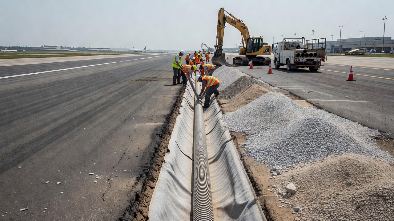
Retrofit Edge Drains
Retrofit edge drains are installed in existing pavements that were originally constructed without subsurface drainage or where the original drainage system has failed. The retrofit installation procedure involves:
Saw-cutting a trench along the pavement edge (typically at the pavement-shoulder joint)
Excavating the trench to design depth (minimum 300 mm from subgrade to pipe centerline)
Placing geotextile fabric lining the trench
Installing perforated collector pipe (minimum 150 mm diameter)
Backfilling with permeable aggregate
Connecting to outlet pipes with concrete headwalls
Marking outlets with reference markers
Performance of Retrofit Edge Drains — California DOT Study
A comprehensive Caltrans evaluation of retrofit edge drains found dramatic performance improvements:
Parameter
Undrained Pavement
With Retrofit Edge Drains
Average faulting rate
0.006 in/year
0.0003 in/year (95% reduction)
Constructed-with-drains rate
0.002 in/year
0.0005 in/year (drained portions)
The study concluded that retrofit edge drains greatly reduced the rate of step faulting of existing PCC pavements. Faulting was almost completely arrested after installation. Similar results were documented on the Valencia-Tarragona Toll Road in Spain, where faulting was nearly completely arrested following retrofit edge drain installation on a jointed concrete pavement that was experiencing rapid deterioration.
Illinois CRCP Study
Experimental edge drains installed on three continuously reinforced concrete pavement (CRCP) projects reduced punchouts by an average of 24%. The six-state concrete pavement performance study further found that edge drains increased service life for jointed concrete and JRCP, and for pavements susceptible to D-cracking, there was a large decrease in joint deterioration and pumping. In Illinois specifically, edge drains provided a 50% increase in service life in terms of joint deterioration rate.
Geocomposite Edge Drains
A geocomposite edge drain is a manufactured product using geotextiles, geogrids, geonets, and/or geomembranes in composite form, used as an edge drain in place of trench-pipe construction. Per FAA §G-1.3.6, geocomposite edge drains:
Require FAA modification to standards approval (FAA Order 5100.1) before use on AIP-funded projects
Should be considered only for pavements without a drainage layer
Feature a panel-shaped perforated plastic core (not round pipe), with a 1.5-inch slim profile permitting a narrow trench and faster installation
Offer up to twice the soil contact area compared to 4-inch round pipe, draining a given quantity of water in 60% of the time
Edge Drain Inspection
Edge drain condition assessment is a critical component of comprehensive pavement inspection. Per FAA AC 150/5320-5D §G-7, drainage systems must be inspected regularly because “an improperly maintained drainage system can cause more damage to the pavement structure than if no drainage were provided at all.”
Visual Inspection (Annual)
Per FAA §G-7.1, visual inspection at least once per year includes:
Checking for crushed outlets
Excessive vegetative growth at outlets and daylighted openings
Clogged/debris-filled daylighted openings
Condition of headwalls (cracking, spalling, displacement)
Presence of erosion at outlets
Missing rodent screens at pipe outlets
Ditch depths — measuring to ensure outlet clearance is maintained
Pavement Condition Evaluation (Every 2 Years)
Per FAA §G-7.1, the pavement condition is evaluated for moisture-related distress:
PCC pavements: pumping, faulting, D-cracking
AC pavements: fatigue cracking, stripping (moisture-induced damage)
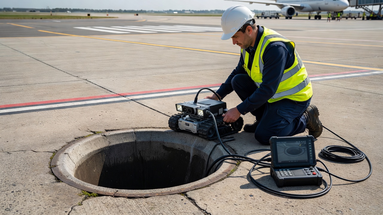
Video Inspection (As-Needed)
Per FAA §G-7.2, CCTV video inspection is performed whenever evidence of drainage-related problems is observed. Video inspection detects:
Clogged drains due to silting (sediment accumulation)
Intrusion of surrounding soil through geotextile failures
Ruptured pipes (crushed or collapsed sections)
Broken connections at joints and outlet tees
Improper connections between outlet pipe and headwall
CCTV inspection is also used for construction acceptance to detect crushed or ruptured drainage pipes, improper connections, and problems with outlet pipe-to-headwall connections before the system is covered.
The inspection equipment consists of:
Waterproof color video camera (typically 71 mm / 2.8 in diameter to negotiate 102 mm x 102 mm plastic tees)
6 high-intensity lights
Portable color control unit with 203 mm (8 in) monitor
150 m push rod with counter
VHS recorder or digital recording system
Evidence of Drainage Problems
Field indicators that trigger video inspection include:
Water ponding on the pavement surface in areas where drainage should be adequate
Wet spots or softened areas along the pavement edge
Greener or more vigorous vegetation along the drain line (indicating excess soil moisture)
Standing water at outlet structures without flow during wet conditions
Visible sediment at outlet pipes
Evidence of pumping (light-colored stains at joints extending onto shoulders)
FHWA Inspection Findings
An FHWA Video Inspection Study of highway edge drains across multiple states found that only one-third (1/3) of edge drains inspected were functional. The remaining two-thirds had significant blockages, structural damage, or other defects preventing proper operation. This alarming statistic underscores the importance of regular inspection and proactive maintenance.
Consequences of Edge Drain Failure
When edge drains fail to function, water backs up within the pavement structure, initiating a cascade of deterioration mechanisms that dramatically shorten pavement service life.
Pumping
Pumping is the ejection of water and fine soil particles from beneath concrete pavement slabs under traffic loading. When a heavy wheel load passes over a joint or crack, the slab deflects downward, pressurizing water trapped in the pavement structure. The pressurized water flows laterally, carrying suspended fine particles from the base and subgrade. When the wheel load passes, the slab rebounds, creating suction that draws more water and fines into the void beneath the slab.
The visual evidence of pumping is a light-colored stain on the pavement surface at joints and cracks, extending onto the shoulder. In advanced cases, water may be visibly ejected from joints under passing traffic. The major factors contributing to pumping are: excess water in the pavement structure, erodible base or subgrade materials, and high volumes of heavy wheel loads. Each pumping event removes more material from beneath the slab, increasing the void space and allowing greater slab deflection under subsequent loads.
Faulting
Faulting is the vertical displacement of adjacent concrete slabs at a joint, where the approach slab is higher than the leave slab. Faulting is the direct result of pumping: as fines are ejected from beneath the leave slab, a void develops. The leave slab loses support and settles under traffic loading, creating a step at the joint.
Faulting is measured in millimeters of vertical offset:
3 mm (1/8 in): Noticeable bump for vehicle or aircraft traffic
6 mm (1/4 in): Significantly increases dynamic loading, accelerating further deterioration
10 mm (3/8 in) and above: Safety hazard, particularly for aircraft where impact can damage landing gear components
Faulting propagates rapidly through a positive feedback loop: each vehicle passage increases the dynamic load at the faulted joint, which increases pumping, which accelerates material loss, which increases faulting.
Freeze-Thaw Damage
Freeze-thaw damage occurs when water trapped within the pavement structure freezes and expands. The volume expansion of water upon freezing is approximately 9%, but the damaging potential is far greater because confined expansion generates pressures exceeding 220 MPa (32,000 psi).
Three manifestations of freeze-thaw damage:
D-cracking: Aggregate particles near joints absorb water, which freezes and fractures the aggregate from within, progressing from the bottom of the slab upward
Frost heave: Formation of ice lenses in frost-susceptible subgrade soils causes upward displacement of the pavement surface — up to 60% heave in soils, 300% in laboratory conditions
Thaw weakening: When ice lenses melt in spring, the saturated soil has dramatically reduced bearing capacity — reductions of 50% or more are typical, leaving the pavement extremely vulnerable to traffic damage
The combination of frost heave and thaw weakening creates a compounded damage cycle: frost heave damages the structure during winter, and thaw weakening leaves it vulnerable during spring. Each freeze-thaw cycle ratchets the damage upward.
Subgrade Weakening
Water saturation reduces subgrade strength and stiffness dramatically:
Fine-grained soils (clays and silts): Undrained shear strength of a saturated clay subgrade may be only 10% to 20% of its strength at optimum moisture content
Granular soils: Modulus can be reduced by 50% or more compared to the same material at optimum moisture conditions
The mechanism of subgrade weakening is often invisible from the surface. A pavement may appear structurally sound while the subgrade beneath is progressively softening, losing support, and allowing excessive deflections that fatigue the surface layers. By the time distress appears at the surface, the subgrade damage is often severe and requires full-depth reconstruction.
Quantitative Damage Rates
Research has documented the devastating effect of water on pavement performance:
Source
Finding
Barenberg & Thompson (Illinois test track)
Rate of damage with excess water: 100 to 200 times greater than without
WASHO Road Test
Damage rates 70,000 times greater during spring thaw vs dry summer
AASHO Road Test
Rates of damage 40 to 50 times greater in wet vs dry periods
Cedergren (1976)
Estimated $217 billion of $329 billion in repairs (1976-1990) could be saved with well-drained pavements
FHWA drain study (1998)
Only one-third of edge drains inspected were functional
Illinois DOT
Edge drains provided 50% increase in service life
Edge Drain Maintenance
Proper maintenance is essential to keep edge drains functional. The most critical warning from FAA guidance: “An improperly maintained drainage system can cause more damage to the pavement structure than if no drainage were provided at all.” This is because a clogged drainage system traps water within the pavement structure, creating permanently saturated conditions that accelerate all forms of moisture-related distress.
Jetting (Flushing)
Per FAA §G-7.3.1, collector drains and outlets should be flushed periodically with high-pressure water jets. The purpose is to loosen and remove sediment buildup within the system. A dual outlet system facilitates this by allowing sections to be flushed in sequence.
Key parameters for effective flushing:
Flushing velocity should be sufficient to transport accumulated sediment: typically 0.6 to 1.5 m/s (2 to 5 ft/s)
Higher velocities (up to 3 m/s / 10 ft/s) may be required for consolidated or clay-rich sediment
For airport pavements, flushing water quality is important: discharge must be collected and treated if it contains fuel residues or deicing chemicals
Annual flushing is typical for most systems; more frequent flushing for areas with erodible soils
Rodent Exclusion
Rodent damage is a surprisingly common and serious problem. Rats and mice enter drainage pipes through outlets, building nests that can completely block the pipe cross-section. Rodent nests consist of organic material bound together with urine and feces, creating a dense mass that is difficult to flush.
Rodent exclusion measures:
Flap gates or one-way valves at outlet pipe ends — allow water to exit but prevent animal entry
Threaded or bolted cleanout covers with gaskets for a rodent-proof seal
Wire mesh screens at outlets (easily removable for cleaning)
Regular inspection for rodent activity: droppings at outlets, burrowing at the outlet apron, musty odors from nest material
All missing rodent screens should be repaired or replaced immediately during inspection.
Outlet Repair
Damaged pipes and headwalls — repair or replace
Missing outlet markers — replace to ensure maintenance crews can locate outlets
Area around outlets — kept mowed to prevent vegetation from blocking flow and to facilitate access
Erosion at outlets — repair with riprap aprons, concrete splash pads, or energy dissipators
Ditches — mowed, debris and silt removed periodically to maintain adequate outlet clearance (minimum 150 mm above ditch flow line)
Common Maintenance Failures Identified by FHWA
FHWA studies documented the following recurring problems:
Crushed/punctured outlets — most likely damaged during construction, left unattended for long periods
Sediment-filled drains — especially at pipe sags and slopes below 1%
Missing rodent screens at outlets
Missing outlet markers — outlets cannot be found, so no maintenance can be performed
Erosion around outlet headwalls
Shallow ditches — inadequate slopes, clogged with vegetation
Pipe collapse — identified by video inspection
90° tee connections — camera and cleaning equipment cannot navigate sharp turns
NCHRP Synthesis 285 concluded: “Maintenance efforts vary between good and nonexistent within a state and among different states. There is an apparent disconnect between maintenance, design, and construction in many state agencies. Many drainage system failures are traced to poor construction and inspection.”
Edge Drains in Airport Pavements
Airport pavement edge drains face unique demands that distinguish them from highway applications. Aircraft wheel loads are substantially higher (a Boeing 747-400 main gear tire load exceeds 22,000 kg / 48,500 lbs, compared to approximately 9,000 kg / 20,000 lbs for a heavy truck), and the consequences of pavement failure — aircraft damage, runway closure, safety incidents — are far more severe.
FAA Regulatory Requirements
The FAA requires that all edge drains under airfield pavements comply with Item D-705 (Pipe Underdrains for Airports) in AC 150/5370-10H. Plastic pipe must comply with Item D-701 (Pipe for Storm Drains and Culverts). Geocomposite edge drains require FAA modification to standards approval (FAA Order 5100.1).
Airport-Specific Design Criteria
Parameter
Airport (FAA)
Highway (Typical)
Drainage criterion
85% drainage in 24 hours (runways/taxiways)
50% drainage in 10 days
Design storm
1-hour duration, 2-year return frequency
Varies
Infiltration coefficient
0.50 (assumed)
Varies
Minimum pipe diameter
150 mm (6 in)
Often 100-150 mm (4-6 in)
Outlet spacing
90-150 m (300-500 ft)
Often up to 300 m (1,000 ft)
Wildlife hazard mitigation
Required (bird strike risk)
Not applicable
Structure height restriction
75 mm (3 in) maximum above grade within safety area
No equivalent
Wildlife Hazard Mitigation
The FAA requires that drainage features be designed to eliminate or mitigate features that could attract hazardous wildlife on or around airports. Standing water in ditches, detention basins, and outlet areas attracts birds, which pose a serious bird strike risk to aircraft. Drainage design must:
Minimize ponding and standing water
Provide steep side slopes that discourage wading birds
Incorporate covers or screens on outlet structures
Ensure outlets remain clear and flowing (stagnant water attracts wildlife)
Structure Height Restriction
Per 14 CFR Part 139, the height of any drainage structure located within a safety area is restricted to 75 mm (3 inches) or less above grade. This includes outlet headwalls, cleanout covers, and access risers. Structures exceeding this height present a collision hazard to aircraft that may inadvertently leave the paved surface.
Redundant Systems
Airport pavement subsurface drainage typically incorporates redundant systems, with both edge drains and permeable bases installed as standard practice. The FAA recommends monitoring systems to ensure continual function, particularly where pavements are constructed below the permanent or seasonally high water table. Redundancy is essential because the consequences of drainage failure at an airport are unacceptable.
Daylighted Permeable Bases
High-traffic airport pavements, particularly main runways serving commercial aviation, are often designed with daylighted permeable bases where the permeable layer extends to the embankment slope without collector pipes. This approach, endorsed by FAA standards, eliminates the risk of pipe blockage and simplifies maintenance. The daylighted base edge is sloped at 3% toward the ditch, with the bottom of the exposed edge at least 150 mm (6 in) above the 10-year storm flow line.
Edge Drain vs Permeable Base
Edge drains and permeable bases are complementary components of a complete subsurface drainage system, not alternatives. Each serves a distinct function:
Feature
Permeable Base (Drainage Layer)
Edge Drain (Collector)
Function
Horizontal drainage of water through the pavement structure
Collection and removal of water at the pavement edge
Perforated pipe (CPE/PVC) with permeable aggregate backfill
Mandatory when?
Required when subgrade permeability <6 m/day
Mandatory when drainage layer is present
Gradation
Open-graded with <2% passing No. 16 sieve
Aggregate backfill around pipe
How They Work Together
The complete drainage system has four essential components:
Open-graded base drainage layer (full width) — conveys water laterally
Edge drain (longitudinal collector pipe in trench) — collects water at pavement edge
Outlet pipes (suitably sized and spaced) — discharge water from the system
Outlet markers and protection — enable maintenance and prevent damage
Critical design principle: Each flow segment must have higher discharge capacity than the preceding segment (drainage layer → edge drain → outlet pipe → disposal). Without functioning edge drains, a permeable base is useless — water will reach the pavement edge but have no path to exit the structure.
Open-Graded Material (OGM): >1,500 m/day (>5,000 ft/day); effective porosity 0.32
Maximum lift thickness: 150 mm (6 in)
Drainage criterion (runways/taxiways): 85% drainage within 24 hours
Drainage criterion (aprons): 85% drainage within 10 days
MnDOT Comparison Study
The Minnesota DOT study (1995) comparing pavement drainage systems found:
Permeable asphalt-stabilized base drained the most water within 2 hours after rainfall ended, providing the driest conditions
All sections with permeable bases required longitudinal edge drains for effective drainage
The combination of permeable base + edge drains significantly outperformed edge drains alone with dense-graded bases
Virginia Case Study — Critical Failure Mode
A documented case study from Virginia illustrates the importance of proper edge drain connection to the permeable base. An open-graded drainage layer was not continued to the edge drain, so trapped water seeped vertically and abraded the soil cement subbase. This led to localized severe faulting, pumping, and cracking — a failure that could have been prevented by ensuring a continuous drainage path from the permeable base to the edge drain.
Pavement drainage in Appendix 6; refers to State practices
ICAO
Annex 14, Volume I
Aerodrome Design and Operations (pavement strength)
FAA
AC 150/5320-5D (2013)
Primary source — Airport Drainage Design; Appendix G is the definitive FAA guidance on subsurface pavement drainage and edge drains
FAA
AC 150/5320-6G (2021)
Airport Pavement Design and Evaluation; §3.7 drainage layers
FAA
AC 150/5370-10H
Standards for Specifying Construction of Airports (Item D-701 for pipe, Item D-705 for underdrains)
FAA
AC 150/5300-13
Airport Design (cross slopes, geometry)
FHWA
FHWA-SA-98-044
Video Inspection of Highway Edgedrain Systems
FHWA
FHWA-SA-92-008
Drainable Pavement Systems (Demonstration Project 87)
AASHTO
M 252
Corrugated Polyethylene Drainage Pipe
AASHTO
M 278
PVC Pipe (Class PS46)
AASHTO
M 28890
Geotextile Specification
Summary
Pavement edge drains are an engineered subsurface drainage component that collects and removes water from the pavement structure, preventing the cascade of moisture-related distress mechanisms — pumping, faulting, freeze-thaw damage, and subgrade weakening — that dramatically shorten pavement service life. Per FAA AC 150/5320-5D, edge drains require a minimum 150 mm diameter perforated pipe with geotextile wrap (AOS ≤ 0.212 mm), minimum 0.15% slope, and outlet spacing of 90 to 150 m. Regular inspection — visual (annual), CCTV video (as-needed), and pavement condition evaluation (every 2 years) — is essential to maintain function and identify blockages, structural damage, and outlet problems before they lead to pavement failure.
The performance data is unequivocal: well-maintained edge drains reduce faulting rates by up to 95%, increase pavement service life by 30% to 100%, and are the single most cost-effective investment in extending pavement longevity. The combination of a high-permeability drainage layer with properly designed, installed, and maintained edge drains forms the complete subsurface drainage system that FAA standards require for all airport pavements except those in the most favorable conditions.
For consultation on pavement edge drain design, inspection, and maintenance for airport or highway applications, contact our engineering team.
Frequently Asked Questions
A pavement edge drain is a longitudinal subsurface drainage system installed along the edge of a pavement. It consists of a perforated collector pipe (typically 150 mm diameter) placed in a narrow trench lined with geotextile fabric and backfilled with clean aggregate. The edge drain collects water that infiltrates through the pavement surface and drains laterally through the permeable base, then conveys it to regularly spaced outlet structures for discharge into ditches or storm drains.
Edge drains are critical for airport pavements because trapped water causes rapid structural deterioration under heavy aircraft loads. Water within the pavement structure leads to pumping (ejection of fines from beneath concrete slabs), faulting at joints, D-cracking in freeze-thaw climates, and subgrade weakening. FAA standards require subsurface drainage for all airport pavements except those in non-frost areas with highly permeable subgrade exceeding 6 m/day, or flexible pavements less than 200 mm thick in non-frost areas.
FAA AC 150/5320-5D specifies minimum 150 mm (6-inch) diameter collector pipe, minimum 0.15% slope, outlet spacing of 90 to 150 m (300 to 500 ft), and geotextile wrap with AOS not exceeding 0.212 mm for the edge drain trench filter. Pipe materials include corrugated polyethylene per AASHTO M 252 or PVC per AASHTO M 278. Outlet pipes must extend at least 150 mm above the 2-year design flow elevation in the receiving ditch.
Edge drain failure leads to water backing up within the pavement structure. FHWA research found that only one-third of inspected edge drains were functional. Consequences include pumping of fines beneath concrete slabs (ejecting material at joints), faulting with vertical displacements exceeding 3 mm, D-cracking from freeze-thaw cycles, subgrade strength reduction of 50% or more, accelerated fatigue cracking, and ultimately structural failure requiring full reconstruction. An improperly maintained drainage system can cause more damage than having no drainage at all.
Edge drains are inspected annually per FAA guidance through visual checks of outlet condition, flow, blockage, and vegetation overgrowth. CCTV video inspection is performed on an as-needed basis when drainage problems are suspected, checking for clogged drains from silting, soil intrusion, ruptured pipes, and broken connections. Maintenance includes periodic high-pressure water jetting (flushing) to remove sediment buildup, repair or replacement of damaged outlet pipes and headwalls, installation of rodent screens at outlets, and replacement of missing outlet markers.
An edge drain is a longitudinal collector pipe system at the pavement edge that collects and removes water. A permeable base is a full-width open-graded aggregate layer beneath the pavement surface with high horizontal permeability (minimum 300 m/day) that conveys water laterally to the edge drains. They work together as a complete system: the permeable base provides horizontal drainage, and the edge drains collect and discharge the water. The drainage layer alone is useless without functioning edge drains and outlets.
Yes, edge drains can be retrofitted to existing pavements by saw-cutting a trench along the pavement edge, excavating to design depth, placing geotextile fabric, installing perforated collector pipe, backfilling with permeable aggregate, and connecting to outlet pipes with headwalls. Retrofit edge drains have proven highly effective — California DOT studies found that retrofit edge drains reduced PCC faulting rates from 0.006 in/year to 0.0003 in/year, an effective 95% reduction, almost completely arresting step faulting.
Edge drain blockages are caused by sediment accumulation (particularly at pipe sags and slopes below 1%), vegetative root intrusion, rodent nesting (mice and rats build nests blocking the full pipe cross-section), crushed or punctured pipes (most likely during construction), geotextile clogging from fine soil migration, and mineral precipitate buildup on pipe perforations. Debris accumulation at outlets from mowing clippings and roadside vegetation also blocks flow. Dual outlet systems are recommended to allow flushing sections of collector drain.
FAA requires lateral outlet pipes at intervals of 90 to 150 m (300 to 500 ft) along edge drains, with additional outlets at the low point of all vertical curves. Outlet pipes are placed at approximately 45 degrees from the direction of flow in the collector drain, with a recommended slope of 3%. The outlet invert must be at least 150 mm (6 in) above the 2-year design flow elevation. Dual outlet systems are recommended to allow flushing. Rodent screens that are easily removable are required at all pipe outlets, and reference markers should be installed for locating outlets during maintenance.
In freeze-thaw climates, edge drains are critical because water in the pavement structure can freeze and expand, causing ice lens formation, frost heave (up to 60% in soils), and subsequent thaw weakening when ice melts. The thaw releases large volumes of free water that must be drained quickly. FAA specifies that in frost areas with F3/F4 soils, edge drain trenches must be placed below frost depth if possible, with side slopes of 1V:10H within the frost depth zone at the pavement edge. If frost depth exceeds 1.2 m (4 ft), the pipe need not be deeper than 1.2 m from the bottom of the drainage layer.
Optimize Your Pavement Drainage Systems
Ensure your airport or highway pavement edge drains are properly designed, inspected, and maintained to extend pavement life and ensure operational safety. Our engineering experts deliver comprehensive drainage solutions for critical infrastructure.
A drain in airport infrastructure is an engineered system for the removal of surface and subsurface water from paved areas such as runways, taxiways, and aprons...
Grooving is the cutting of transverse or longitudinal channels into runway or road pavement surfaces to improve water drainage, increase wet-weather friction, a...
29 min read
Pavement Surface
Runway Safety
+3
Cookie Consent We use cookies to enhance your browsing experience and analyze our traffic. See our privacy policy.