Bridge Bearings
Bridge bearings are critical load-transfer devices at abutments and piers that transmit superstructure forces to the substructure while accommodating thermal mo...
28 min read
Bridge components
Bridge inspection
+3
Bridge expansion joints are structural devices that accommodate thermal movement, creep, shrinkage, and live-load deflection between spans or between the deck and abutments. Covers joint types including strip seal, modular, finger plate, compression seal, sliding plate, and asphaltic plug. Details selection by movement range, waterproofing integration, installation quality, distress modes, inspection protocols, maintenance strategies, and jointless bridge alternatives.
A bridge expansion joint is a mechanical assembly installed in a deliberate gap left between adjacent bridge deck segments or between a bridge deck and its abutment. Its purpose is to allow the superstructure to expand and contract freely in response to temperature fluctuations, concrete creep and shrinkage, live-load deflections, and seismic displacements, while simultaneously sealing the gap against water, deicing chemicals, and debris. The joint must also transfer wheel loads smoothly across the gap without producing unacceptable impact forces, noise, or ride discomfort.
The primary movement that an expansion joint accommodates is thermal expansion and contraction. Bridge materials expand when temperatures rise and contract when temperatures fall. The coefficient of thermal expansion for steel is approximately 6.5 × 10⁻⁶ per degree Fahrenheit, while normal-weight concrete is about 6.0 × 10⁻⁶ per degree Fahrenheit. Per AASHTO LRFD Bridge Design Specifications Section 3.12, design temperature ranges vary from approximately 80°F in moderate climates to 150°F in cold climates for steel superstructures. For a 200-foot steel girder span in a cold climate, the thermal movement alone can exceed 2 inches between summer and winter extremes.
Secondary movements include concrete creep and shrinkage in prestressed concrete girders. Long-term creep and shrinkage typically add 0.0003 to 0.0006 inches per inch of tributary span length over the service life. For a 200-foot prestressed girder, this adds approximately 0.72 to 1.44 inches of movement at the joint, accumulating over several years after construction. Live-load girder end rotation translates to longitudinal displacement at the bearing, typically adding 0.1 to 0.3 inches on highway loadings depending on bearing offset geometry. Seismic displacement must also be considered in active zones.
The joint delivers watertightness through either an integral elastomeric seal (compression seal, strip seal gland, modular gland), a pourable sealant (silicone or polymer), or a drainage trough that collects and diverts water (finger plate joints). Joints that rely on a drainage trough rather than an integral seal are classified as open joints, and watertightness is provided by the collection and conveyance system below the joint opening. Closed joints incorporate a seal that directly prevents water passage.
According to the Florida Department of Transportation Bridge Maintenance Manual, faulty bridge deck joints contribute to the deterioration of every major bridge component — deck, superstructure, and substructure — by permitting corrosive deicing salts, water, and debris through the gap. Deck ends, beam ends, abutment seats, pier caps, and bearings are all at risk. The significance of keeping bridge joints in a good state of repair cannot be overemphasized.
Selection of the appropriate expansion joint system begins with a single critical parameter: total calculated movement range. The total movement is the sum of thermal movement, creep and shrinkage, live-load rotation, seismic displacement where applicable, and a safety factor (commonly 1.25 per state DOT practice). The joint is then specified by its rated movement capacity, which must equal or exceed this total.
The five system families map to specific movement ranges:
| Joint Type | Movement Range | Typical Span | Typical Service Life | Relative Cost |
|---|---|---|---|---|
| Compression seal | Up to 2 inches | Short to medium | 15 to 25 years | $ |
| Asphaltic plug joint (APJ) | Up to 1.5 inches | Under 60 feet | 7 to 12 years | $ |
| Strip seal | Up to 4 inches | Medium | 20 to 30 years (gland 10 to 15) | $$ |
| Finger plate | 4 to 12+ inches | Long steel girder | 30+ years | $$$ |
| Modular (MBEJ) | 4 to 32+ inches | Long, large movement | 25 to 35 years | $$$$ |
The base equation for thermal movement is ΔT = α × L × (Tmax − Tmin), where α is the coefficient of thermal expansion, L is the tributary span length contributing to the joint, and (Tmax − Tmin) is the design temperature range. For a 200-foot prestressed concrete girder in a moderate climate with a 100°F temperature range, the thermal component equals 1.44 inches. Adding 0.96 inches for creep and shrinkage and 0.20 inches for live-load rotation produces a subtotal of 2.60 inches. A 1.25 safety factor adds 0.65 inches, yielding a total design movement of approximately 3.25 inches — at the upper edge of strip seal capacity. The designer would select a 4-inch strip seal or step up to a single-cell modular system.
Skew angle profoundly affects joint selection and sizing. On skewed bridges, the joint experiences racking displacement parallel to the joint line in addition to opening and closing perpendicular to it. The WisDOT Bridge Manual specifies that on skews over 30 degrees, the actual racking displacement should be limited to 60 percent of the seal rated capacity. On skews over 45 degrees, the limit drops to 50 percent. Strip seals must be oversized to compensate for racking at high skews, and some manufacturers offer 5-inch glands for installations requiring 4 inches of movement on high-skew structures.
Bridge grade also affects joint selection. Joints on steep grades experience differential movement at the high and low sides and may require enhanced drainage provisions. Asphaltic plug joints soften above approximately 140°F and can rut under heavy slow-moving truck loads on grades, limiting their application on steep approaches. Strip seals can handle grades up to 5 percent with appropriate gland sizing.
Traffic volume and speed influence the choice between flush joints (APJ, compression seal) and joints with exposed steel rails (strip seal, modular). High-speed highways require smooth transitions without tripping hazards. Finger plate joints provide excellent ride quality at speed because the wheel never crosses an open gap — it transitions across overlapping steel. Modular joints, while watertight, produce more noise and vibration at speed compared to finger plates, which is why finger plates remain the preferred choice for long-span steel bridges carrying high-speed traffic.
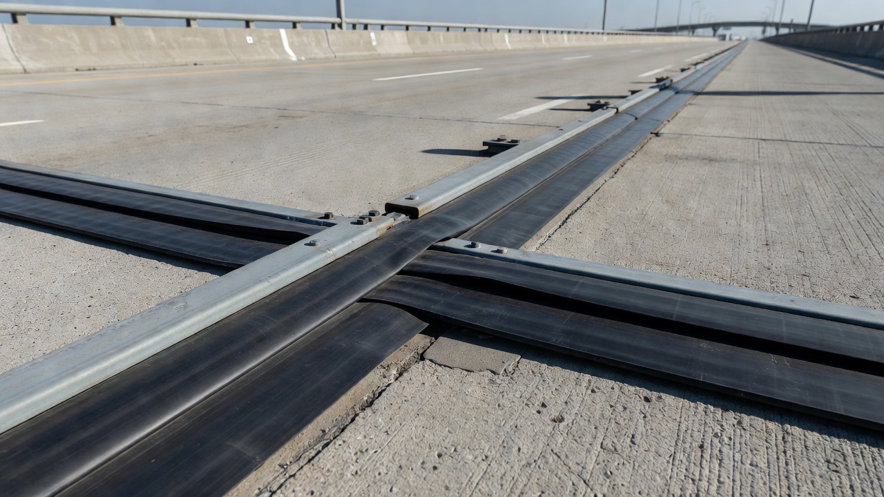
The strip seal joint is the workhorse system for typical short-to-medium span bridges. It consists of two steel edge rails — typically extruded or cast steel — anchored into concrete deck headers, with a continuous elastomeric gland (EPDM or neoprene) mechanically locked between them. The gland flexes in a V-shape as the joint opens and folds flat as the joint closes. The gland is the wearing component; the rails are the structural component that transfers wheel loads to the deck.
Strip seals dominate the 1- to 4-inch movement range because they are simple, fast to install, and the gland can be replaced without removing or disturbing the steel rails. A gland replacement is a single-shift overnight closure on a typical lane. The rails themselves typically remain in service for 20 to 30 years. Per WisDOT standards, the minimum strip seal size for new construction is 4 inches, and the minimum transverse roadway surface opening between extrusions must be 1.5 inches to facilitate gland installation.
Gland performance depends on proper installation. Per the WisDOT Bridge Manual, performance evaluations of in-service strip seal joints indicate that glands are not always installed correctly. Common errors include failure to insert both ears of the neoprene lug into the steel extrusion and installation of the gland upside down. Manufacturers are now required to label “Topside” on neoprene glands prior to shipping. The lubricant-adhesive applied during installation acts initially as a lubricant then cures to form an adhesive membrane between the contact surfaces.
Strip seals are curved up into curb and parapet sections with cover plates covering the resulting recess. Median and sidewalk sections also require cover plates. The Wisconsin DOT standard details require that for strip seal installations on skews over 45 degrees, the seal must be oversized to compensate for racking.
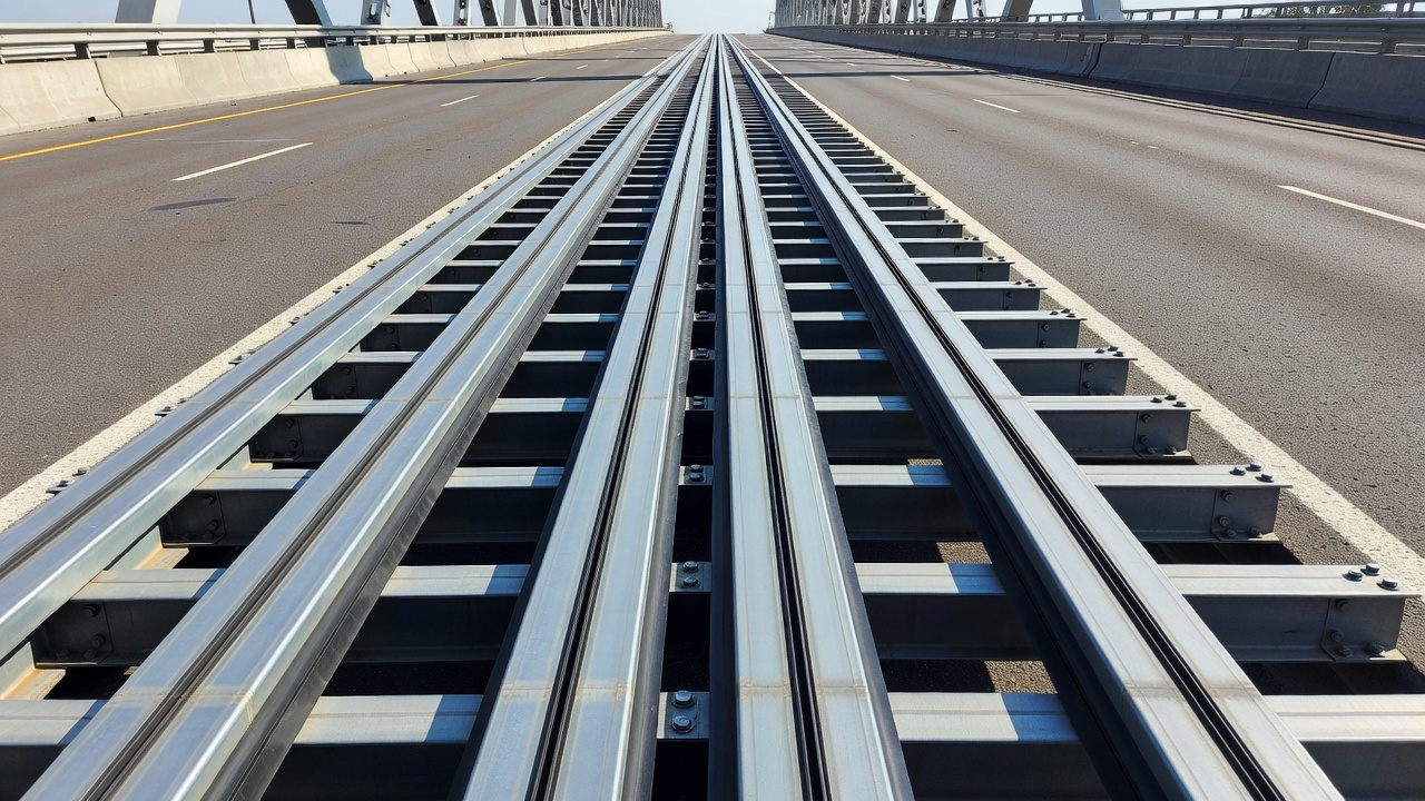
A modular expansion joint is effectively a scaled-up strip seal. Multiple parallel center beams sit between the two edge rails, each separated from the next by an elastomeric gland. Each individual gap accommodates a fraction of the total movement, multiplied by the number of cells. A 4-cell MBEJ with a 4-inch per-cell capacity gives 16 inches of total movement.
The center beams are carried on transverse support bars that slide through bearing boxes anchored into the substructure. Two design philosophies dominate: single support bar (SSB) systems use one bar per beam sliding through a single bearing per side, providing simpler kinematics and fewer wear surfaces. Multiple support bar (MSB) systems give each beam its own dedicated support bar with springs and equidistance devices, offering more redundancy under fatigue loading. Both designs are used by major DOTs; selection depends on fatigue category requirements and agency preference.
MBEJs are the most expensive joint family on a per-linear-foot basis and the most disruptive to replace. Replacement requires demolishing the deck blockout, removing the support bar bearing assembly, and recasting header concrete around the new unit. Multi-week stage construction with traffic diversion is the norm. Proactive maintenance — gland replacement and bearing inspection — is essential to delay the full replacement event.
Modular joints are governed by AASHTO LRFD Section 6 fatigue categories for the welded center-beam-to-support-bar connection. Live load rating follows AASHTO HL-93 design vehicle requirements plus project-specific permit loads. Modular geometry tolerates significant skew with proper corner detailing.
Finger plate joints use two interlocking sets of steel cantilever fingers anchored into the deck header. The fingers overlap with a small clearance and slide past one another as the joint moves. Wheel loads ride directly on the steel surface, and watertightness is handled separately by an elastomeric drainage trough suspended below the fingers.
Two finger plate types exist: cantilever fingers, supported only at the anchored root (common up to 4 inches of movement), and supported or sliding fingers, where the tips ride on a support shelf during compression, eliminating cantilever bending (used for 4 to 12+ inches of movement on heavily loaded decks). Finger length and tooth geometry are tuned to span length and traffic requirements. Some agencies require a maximum finger gap of ¾ inch parallel to traffic direction for motorcycle and bicycle compatibility.
The ride quality advantage of finger plates is substantial. The wheel never crosses an open gap — it transitions across overlapping steel. This makes finger plates the preferred joint type on long-span steel girder bridges where ride quality and noise mitigation are primary requirements. Per the WisDOT Bridge Manual, finger and sliding plate details are currently maintained only for joint maintenance and retrofitting; watertight expansion devices such as strip seals and modular types are recommended for new structures.
The drainage trough below the fingers is the actual waterproofing element and the most common failure point. Troughs clog with deicing salt sediment, pavement millings, and litter. Cleanout access through side panels and slope-to-drain detailing are critical design features. A clogged trough sends runoff directly into the bearings, defeating the entire system.
A compression seal is a preformed polychloroprene (neoprene) extrusion forced into a joint gap that is permanently narrower than the unrestrained seal width. The seal stays watertight by remaining in compression across the full thermal cycle. Two types exist: open cell seals with internal webbing that allows compression while maintaining a stable interface with the deck end, and closed cell foam seals made of low-density ethylene vinyl acetate polyethylene bonded with two-component epoxy adhesive.
Open cell compression seals accommodate movements up to 2.5 inches. Because they rely entirely on compression for watertightness, sizing is critical — the seal must be large enough for the joint opening required at the coldest temperature. Closed cell foam seals work over a range of approximately 60 percent compression and 30 percent tension, accommodating movements up to 4 inches with some products. The epoxy bonding means closed cell foam seals do not rely solely on compression for watertightness.
Per AASHTO M 297, compression seal materials for bridge applications must meet specific physical property requirements. The WisDOT Bridge Manual notes that compression seals are no longer recommended for expansion joints due to a tendency to leak over time; they are used only for longitudinal construction joints or rehabilitation projects where the existing seal has pulled out.
Installation requires thorough cleaning of joint faces, application of lubricant-adhesive to the seal sides and joint faces, proper insertion tools (hand or machine tools that compress and eject the seal — screwdrivers and pry bars are not allowed), and stretching limited to 5 percent maximum. The seal must be installed below the pavement surface with a minimum depth recess of ¼ inch.
An asphaltic plug joint is a flexible, in-place joint made by saw-cutting a blockout across the deck (typically 18 to 24 inches wide and 2 to 3 inches deep), bridging the deck gap with a steel plate, and filling the blockout with polymer-modified asphalt binder mixed with single-size aggregate. The result is a flush, pavement-like surface bonded to both deck headers.
APJs handle up to approximately 1.5 inches of total movement and are best suited for bridges under 60 feet with a single fixed bearing. The binder softens above approximately 140°F, making rutting under heavy slow-moving truck loads the dominant failure mode. Service life ranges from 7 to 12 years — shorter than steel-based systems but offset by rapid placement.
APJ shines as a retrofit. A failed strip seal or compression seal on a short bridge can be saw-cut out, the blockout cleaned, and a new APJ placed in a single overnight or weekend closure. No new headers, no anchorage drilling, no waiting for concrete cure. The minimal traffic impact often justifies the shorter lifecycle for maintenance programs managing many small bridges.
Failure modes include rutting under heavy truck loads in hot weather, longitudinal cracking over the bridging plate edge, debonding from the deck header at the blockout edge, and aggregate stripping under repeated wheel impact.
Sliding steel plate joints are semi-open joints where a steel plate slides over the gap as the joint opens and closes. Water and light debris can pass through the joint. A sealant placed in the joint prevents some water passage and prevents debris accumulation that could block movement. Modern practice favors strip seals over sliding plate joints for new construction, but sliding plate details are maintained for rehabilitation of existing installations.
Expansion joints are the single most vulnerable point in a bridge waterproofing system. The joint itself must be watertight, but watertightness also depends on the integrity of the interface between the joint and the deck waterproofing membrane. If the membrane terminates short of the joint, water entering from the wearing surface bypasses the joint seal entirely and runs down the header face.
Integration starts with the header or nosing — the material bonded to the deck and approach slab that provides a vertical surface for joint attachment and resists wheel loads. Headers are typically made of hydraulic cement concrete or elastomeric concrete (polymer concrete). Elastomeric concrete headers offer superior durability, faster cure times, and better bond to sealants. Per the FDOT Bridge Maintenance Manual, polymer concrete headers are recommended for strip seal and modular joint installations because they provide a dense, low-permeability substrate that resists chloride penetration and spalling.
The waterproofing membrane should extend to the joint header and be lapped or sealed at the interface. For asphaltic plug joints placed over an existing waterproofing system, the membrane must be intact at the saw-cut edges of the blockout. Any membrane damage at the blockout perimeter becomes a path for chloride-laden water to reach the deck.
For finger plate joints, the drainage trough is the critical waterproofing element. Troughs must be sized to handle the design storm event, sloped to drain to discharge points (typically at abutment seats or through downspouts), and provided with cleanout access panels. A clogged trough is functionally equivalent to an open joint.
For modular joints, the gland system provides the primary seal, but redundancy comes from the support bar bearing boxes, which are often configured to collect and drain any water that bypasses the primary gland. The bearing boxes should be inspected annually for evidence of leakage.
The AASHTO LRFD Bridge Design Specifications require that joint details be designed to prevent water from reaching the substructure. This includes detailing drip edges at the bottom of the joint, providing adequate overhang, and ensuring positive drainage away from the joint area.
Installation quality directly determines joint service life. Poorly installed joints fail prematurely regardless of the quality of the components. Joint installation involves multiple critical steps, each with specific quality control requirements.
Header preparation is the foundation of joint performance. The concrete or elastomeric concrete header must have clean, sound, vertical faces. Any spalls, honeycombing, or reinforcing steel exposed at the header face must be repaired before joint installation. For strip seals and modular joints, the header dimensions must match the manufacturer specifications for rail anchorage. The header must be cured to the specified strength before joint loading.
Pre-set opening is one of the most critical installation parameters. A joint that is set too wide on a hot day will go into compression beyond its rated range on a cold winter morning. The manufacturer provides a pre-set table that specifies the installation gap as a function of the ambient temperature at time of installation. The WisDOT Bridge Manual provides specific joint opening dimensions at a mean temperature of 45°F for Wisconsin installations, with instructions to show temperature tables on the plans for expansion lengths exceeding 230 feet.
Anchorage installation for steel rails and armor plates must follow the manufacturer specifications. Welded shear studs must be free of slag and of proper length. Curved or bent shear studs (common where reinforcement congestion exists) must be replaced per the contract documents. The FDOT manual notes that conflicts between bottom shear studs and K-bars in diaphragms are a recurring issue that requires careful detailing to resolve.
Neoprene gland installation for strip seals and modular joints requires proper lubrication, proper seating of both ears of the gland into the extrusion channels, and confirmation that the gland is not installed upside down. Stretching the gland more than 5 percent is not permitted. The gland should be installed in one continuous length for any given joint application.
Sealant placement for pourable joints requires a backer rod to prevent sealant from falling through the gap. The sealant should not bond to the backer rod. The sealant profile must be thinner in the middle than at the deck ends — this hourglass shape ensures that as the joint opens, the seal stretches within its thinnest cross-section at the middle, rather than at the ends where it could debond from the header.
Curing time before traffic loading is specified by the manufacturer for sealants and by the concrete specification for headers. Opening a joint to traffic before adequate cure is a common cause of premature header spalling and seal debonding.
Bridge expansion joints are among the most highly stressed and exposed components on a structure. They endure direct wheel impact, thermal cycling, ultraviolet radiation, deicing chemical attack, and debris accumulation. The following distress modes are documented in the FDOT Bridge Maintenance Manual and FHWA Bridge Preservation Guide.
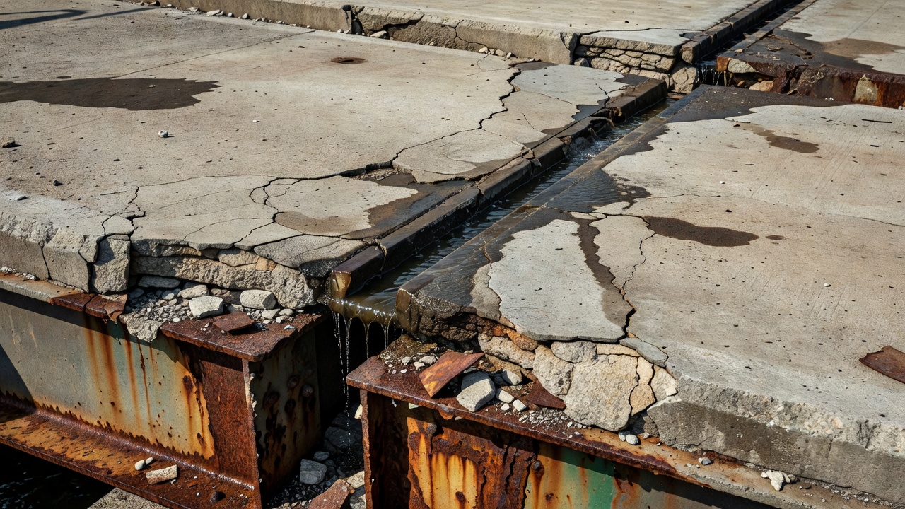
Leakage is the most consequential joint distress. Leakage allows water and chlorides to reach bearings, girder ends, end diaphragms, and abutment seats. The FDOT manual shows examples where leakage has produced major deterioration of steel beam ends, concrete end diaphragms, and bearings. Leakage can occur through the seal itself (gland tear, compression seal relaxation, sealant debonding), through the seal-to-rail interface (improper gland seating), or through the header-to-deck interface (header spalling or shrinkage cracking).
Condition of the road surface adjacent to the joint is critical. Differential settlement between the approach slab and the bridge deck produces a bump at the joint that induces impact loading. The backwall approach slab settlement drives impact loads that break header concrete, displace armor, and damage seals. This distress creates a feedback loop — the bump worsens the joint damage, which worsens the bump.
Seal condition must be assessed for neoprene glands, compression seals, and pourable sealants. Neoprene glands fail by ozone cracking, abrasion from debris, thermal aging, and chemical attack. Compression seals fail by relaxation (loss of compression force), extrusion, or adhesive bond failure. Pourable sealants fail by debonding, cohesive splitting, or hardening. The FHWA Bridge Preservation Guide recommends gland replacement at the first sign of through-cracking.
Debris accumulation within the joint gap is a primary cause of joint binding and structural damage. Incompressible materials (gravel, broken concrete, tire fragments, snowplow scrapings) packed into the joint prevent normal closure. When the deck attempts to close under cold temperatures, the trapped debris forces the deck into compression, potentially damaging the header, spalling concrete at the joint edge, or buckling the steel armoring.
Header material deterioration includes spalling at the joint edge from impact loading, cracking from shrinkage or thermal cycling, and disintegration from freeze-thaw action with deicing salts. Once the header begins to break down, the joint anchorage is compromised and the entire joint system becomes unstable.
Steel armor and rail condition must be checked for corrosion, section loss, weld cracking, anchorage loosening, and fatigue cracking at welded connections. For modular joints, the support bars and bearing boxes require particular attention. Support bar corrosion and bearing wear reduce the equidistance between center beams, causing uneven movement distribution and potential binding.
Impact damage from snowplow blades, heavy equipment, or dropped loads can break header concrete, bend armor rails, shear off anchorage studs, and tear glands. Impact damage is typically localized but requires prompt repair to prevent progression.
Bridge expansion joints are inspected as part of routine bridge inspections under the National Bridge Inspection Standards (NBIS), with the condition rating reported in the bridge inventory under item codes for joints. The FHWA Recording and Coding Guide provides standard condition rating criteria from 9 (excellent) to 0 (failed).
The inspection covers the following elements for each joint type:
For all joint types: leakage evidence on the substructure below the joint; condition of the riding surface approach; debris accumulation; header condition; anchorage condition.
For strip seals: gland condition (cracking, tearing, seating in the extrusion channels); rail condition (corrosion, wear, anchorage integrity); gland replacement history.
For modular joints: gland condition for each cell; equidistance of center beams; support bar bearing condition; drainage paths within the bearing boxes; support bar corrosion.
For finger plates: finger gap dimensions; finger tip condition (wearing, cracking, tip breakage); drainage trough condition (corrosion, clogging, punctures); trough cleanout access; evidence of water bypassing the trough.
For compression seals: seal compression (should be in compression at all temperatures); seal extrusion; adhesive bond condition; seal depth below pavement surface.
For asphaltic plug joints: surface condition (rutting, cracking, raveling); debonding at blockout edges; binder condition (softening, stripping); bridging plate condition (corrosion, displacement).
For sliding plate joints: plate condition (corrosion, wear, displacement); sealant condition; trough condition if present.
The FDOT Bridge Maintenance Manual recommends that inspection findings be documented with photographs and measurements. Joint gap width should be measured and recorded at the time of inspection, as this provides baseline data for monitoring movement. Temperature at the time of inspection should also be recorded.
A proactive joint maintenance program significantly extends joint service life and delays the costly full replacement event. The FHWA Bridge Preservation Guide emphasizes that preventive maintenance of expansion joints is more cost-effective than reactive repairs.
Routine cleaning is the most basic and important maintenance activity. Debris removal from the joint gap, drainage troughs, and bearing boxes prevents the accumulation of incompressible materials that can block movement and cause structural damage. For finger joints, the FDOT manual specifies cleanout of the trough assembly as a routine task. For compression seals and strip seals, the self-cleaning action of tire forces compressing the seal causes debris to bounce up and out — but this only works if the debris does not pack into the seal cavities.
Gland replacement is the primary maintenance activity for strip seals. Glands typically last 10 to 15 years depending on traffic, deicing chemistry, and UV exposure. Gland replacement is a lane-level operation that can be completed in a single overnight closure. The old gland is pulled out of the extrusion channels, the channels are cleaned, and the new gland is lubricated and pressed in using a tire-iron type tool.
Compression seal replacement requires removing the old seal (often by cutting and pulling), cleaning the joint faces, and installing the new seal with proper lubrication and compression. The FDOT manual provides a joint calculator methodology where the required seal width equals the sum of the expected maximum joint opening plus an oversize factor — typically ½ inch minimum.
APJ replacement is a saw-cut-and-fill operation. The old plug is removed within the blockout, the blockout is cleaned, a new bridging plate is installed if required, and the polymer-modified binder with aggregate is placed and compacted flush with the riding surface. The entire operation can be completed in 8 to 12 hours for a single-lane joint.
Header repair addresses spalled or deteriorated concrete at the joint edge. Polymer concrete (elastomeric concrete) is the preferred repair material because it cures rapidly (typically 1 to 3 hours), bonds well to existing concrete, and provides high durability under impact. The FDOT manual specifies polymer concrete for header replacement on strip seal and modular joints.
Full joint replacement is required when the steel components (rails, center beams, support bars) have deteriorated beyond repair, the headers are extensively damaged, or the joint type is being upgraded. Replacement is typically performed during a planned closure with stage construction and traffic diversion. The cost and duration vary significantly by joint type — strip seal replacement is a single-weekend operation, while modular joint replacement can require multiple weeks.
The failure of a bridge expansion joint has consequences that extend far beyond the joint itself. Leaking joints are consistently identified as the primary cause of widespread substructure deterioration in bridges, as documented by the FHWA, AASHTO, and multiple state DOT bridge inspection manuals.
Substructure deterioration begins when chloride-laden water passes through a failed joint seal and runs down the girder ends, bearings, and abutment seats. The chloride ions penetrate the concrete, depassivate the reinforcing steel, and initiate corrosion. The corrosion products expand to approximately 2 to 4 times the volume of the original steel, generating tensile stresses that crack and spall the cover concrete. On steel superstructures, the water causes corrosion of girder ends, bearing assemblies, and connection plates.
Bearing failure is a common consequence of joint leakage. Water and debris that accumulate on the bearing seat accelerate corrosion of the bearing components. For elastomeric bearings, the water can cause delamination of the elastomer layers. For steel bearings, corrosion of pins, rockers, and sliding surfaces restricts movement and induces unintended forces in the superstructure.
End diaphragm deterioration occurs where joint leakage concentrates at the girder ends. The end diaphragm — the transverse beam at the abutment — collects the runoff and deteriorates rapidly. The FDOT manual shows case studies where joint leakage caused complete deterioration of concrete end diaphragms, requiring full replacement.
Abutment seat erosion occurs where water running through the joint erodes the abutment backwall and seat. Over time, this erosion can undermine the bearing support and cause settlement of the superstructure. Soil erosion behind the abutment may also occur, creating voids that compromise approach slab support.
Structural safety implications arise when corrosion has advanced to the point of section loss in primary load-carrying members. Bridge load ratings may need to be reduced. In extreme cases, the bridge may need to be posted for reduced load limits or closed entirely until repairs are completed.
Lifecycle cost impact is substantial. The cost of replacing a failed joint plus repairing corrosion damage to substructure components can be 5 to 10 times the cost of proactive joint maintenance and timely replacement. The AASHTO Small Bridge Expansion Joints Guide specifically addresses cost-effective maintenance strategies to prevent the escalation of joint-related problems.
The most effective approach to eliminating expansion joint failure is to eliminate the joint itself. Jointless bridge construction uses integral or semi-integral abutments to create a continuous structural system without expansion joints. The FHWA Comprehensive Design Example for Prestressed Concrete Girders states that integral abutments are specifically designed to remove expansion joints at the ends of bridges, resulting in jointless bridges that provide long-term serviceability, minimal maintenance requirements, economical construction, and improved aesthetics.
Integral abutments rigidly connect the deck to the abutment, which is supported on a single row of flexible piles (typically steel H-piles). When the bridge expands or contracts, the abutment translates horizontally, and the piles flex to accommodate the movement. Since both end abutments resist the earth pressure through compression in the superstructure, the piles need not be designed for earth loads. This creates a simpler, more robust structural system.
The FHWA design guidance explains that integral abutments are generally used for straight bridges, with bridge length limits based on a total thermal movement of 4 inches (2 inches per end). This yields maximum lengths of approximately 600 feet for concrete bridges and 400 feet for steel bridges in moderate climates. Cold climates impose shorter limits. Integral abutments require select granular fill behind the abutment, lightly compacted to allow translation with minimal resistance. Sharp skew angles are limited because earth pressure forces on skewed abutments produce a torque that twists the bridge in plan.
Semi-integral abutments use a joint at the abutment face but eliminate bearings. The deck is connected to a backwall that moves with the superstructure, while the abutment stem remains stationary. This design reduces the movement demand at the approach slab and is suitable for moderate-length bridges where full integral action is impractical.
Link slabs are a joint elimination technique for continuous multi-span bridges. Instead of a joint over the pier, a reinforced concrete link slab is cast continuous over the pier, with a bond breaker over a defined length to allow rotation. Shear studs are eliminated in the link slab zone to permit the required rotation. The FHWA and FDOT manuals both provide detailed link slab design and construction guidance, including case studies of successful link slab applications.
Slab-over-backwall construction eliminates the abutment joint by extending the deck slab horizontally over the abutment backwall. The slab slides over a bearing surface as the bridge expands and contracts. This detail is used primarily on short-span bridges where thermal movements are small. The FDOT manual provides construction photos of slab-over-backwall installations showing the backwall rebar configuration and the completed bridge railing termination.
Approach slabs are essential components of jointless bridge systems. The FHWA design example specifies that approach slabs be cast on polyethylene sheets to minimize friction, tied to the abutment at one end, and supported on a sleeper slab at the other. A contraction joint at the abutment-approach slab interface provides a controlled crack location. The approach slab bridges over the backfill settlement zone that develops behind integral abutments due to abutment movement and traffic compaction.
The AASHTO LRFD Bridge Design Specifications do not contain detailed design criteria for integral abutments, so individual states have developed their own design guidelines based on past experience. This has led to two approaches: one group designs the piles to resist only gravity loads, ignoring horizontal displacement effects; the other accounts for the combined effects of gravity and horizontal displacement on pile loads and resistance. Both approaches have been used successfully within their respective length and geometric limits.
Jointless bridge construction has become increasingly popular across the United States because it eliminates the dominant source of bridge maintenance cost — expansion joint failure. The Colorado DOT Bridge Design Manual explicitly states that removing existing expansion joints during rehabilitation reduces future inspection and maintenance needs, eliminates the possibility of future joint failure, and can improve ride quality. The Federal Highway Administration continues to promote jointless bridge design through its bridge preservation programs and research initiatives.
Our team provides comprehensive bridge inspection, joint condition assessment, and maintenance planning services to extend the service life of your bridge assets.
Bridge bearings are critical load-transfer devices at abutments and piers that transmit superstructure forces to the substructure while accommodating thermal mo...
An abutment is the end support structure of a bridge that retains the approach embankment, transfers superstructure loads to the foundation, and accommodates th...
Bridge girders are the primary horizontal load-carrying beams supporting the bridge deck, spanning between piers and abutments. Common types include steel I-gir...