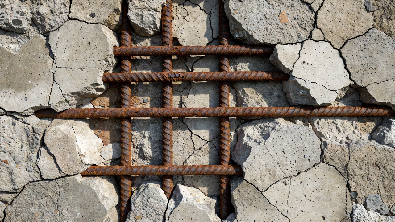
Exposed rebar is a critical structural defect where reinforcing steel becomes visible at the concrete surface due to spalling, delamination, or insufficient cover. It signals advanced deterioration and, if unaddressed, leads to rapid corrosion, section loss, and structural compromise. TarmacView’s defect head detects exposed rebar as a high-severity defect triggering Urgent repair priority.
Exposed Reinforcement in Concrete Structures
Definition and Causes
Exposed rebar — also referred to as exposed reinforcement, visible rebar, reinforcement exposure, or exposed steel — is a condition in reinforced concrete structures where the embedded steel reinforcing bars become visible at the concrete surface due to loss of the protective concrete cover. This is not a standalone material defect but rather the visible manifestation of the terminal stage of several deterioration processes — spalling, delamination, abrasion, or mechanical damage — that progressively remove or displace the concrete that normally encapsulates and protects the steel reinforcement from the environment.
The fundamental role of concrete cover in reinforced concrete is dual. First, it provides the physical barrier that separates steel from environmental aggressors — moisture, oxygen, chlorides from deicing salts or seawater, carbon dioxide from the atmosphere, and other chemical contaminants. Second, it maintains the highly alkaline chemical environment (pH 12.5–13.5) produced by cement hydration products, primarily calcium hydroxide [Ca(OH)₂] and alkali hydroxides (NaOH, KOH). This alkalinity passivates the steel surface by forming a protective nanometer-thick film of iron oxides and hydroxides — known as the passive film — that reduces the corrosion rate to negligible levels (typically 0.1–1.0 µm/year per ASTM G16 standards). When the concrete cover is lost and the rebar becomes directly exposed to the atmosphere, both protective mechanisms are simultaneously eliminated: the physical barrier disappears and the alkaline environment at the steel surface is replaced by near-neutral pH conditions from atmospheric exposure, enabling rapid active corrosion.
Inspection data from the FHWA National Bridge Inventory shows that exposed rebar is one of the most commonly reported structural defects on reinforced concrete bridges, with over 15% of all concrete bridge decks in the United States showing some degree of reinforcement exposure in the most recent reporting cycle. The economic impact is substantial: the American Society of Civil Engineers (ASCE) 2021 Infrastructure Report Card estimates that corrosion-related concrete deterioration, of which exposed rebar is the most visible indicator, costs the U.S. transportation sector approximately $8–$12 billion annually in direct repair and indirect user delay costs.
Primary Mechanisms Leading to Exposed Rebar
Corrosion-induced spalling is the most prevalent cause of rebar exposure in existing concrete infrastructure. As steel reinforcement undergoes active corrosion — either from chloride-induced depassivation or carbonation-induced depassivation — the rust products (ferrous oxides FeO, ferric oxides Fe₂O₃, and hydroxides Fe(OH)₂ and Fe(OH)₃) form expansive compounds that occupy approximately 2 to 6 times the volume of the original metallic iron consumed, as documented in ACI 222R (Protection of Metals in Concrete Against Corrosion). The exact volume expansion factor depends on the specific corrosion products formed: goethite (α-FeOOH) produces a 2–3× volume increase, lepidocrocite (γ-FeOOH) produces 3–4×, and fully hydrated ferric hydroxide can reach 5–6× volume expansion. This volumetric expansion generates tensile stresses in the surrounding concrete matrix that can reach 50 to 100 MPa under confined conditions — far exceeding the tensile strength of normal structural concrete, which typically ranges from 2 to 5 MPa (or 10–15% of its compressive strength). The resulting tensile fracture propagates from the rebar surface outward to the concrete surface along the path of least resistance, producing the characteristic spalled crater that directly exposes the underlying steel. This mechanism is self-accelerating: once spalling exposes a portion of the bar, the exposed steel corrodes faster, producing more expansive rust, which propagates the spall zone laterally along the bar.
Delamination is a closely related mechanism that often precedes visible spalling. Delamination is a planar separation within the concrete mass, typically occurring along or just above the plane of the top layer of reinforcement — which is also the plane where accumulated corrosion products generate maximum tensile stress. In bridge decks subjected to deicing salt exposure, delamination commonly develops at the interface between the top mat of transverse reinforcement and the cover concrete above it. Delaminated concrete may remain in place and appear sound from the surface, making detection by visual inspection alone unreliable. The standard detection method is acoustic sounding — chain drag on horizontal surfaces (bridge decks) and hammer tapping on vertical surfaces (columns, walls, abutments) — performed per ASTM D4580 (Standard Practice for Measuring Delaminations in Concrete Bridge Decks by Sounding). Delaminated areas produce a characteristic hollow or drum-like sound compared to the solid ringing sound of well-bonded concrete. As delamination progresses and the separated section loses its edge anchorage, it eventually displaces under traffic loading or thermal cycling and falls away, directly exposing the reinforcement.
Insufficient concrete cover during original construction is a contributing factor in a significant and often under-documented percentage of exposed rebar cases. ACI 318 (Building Code Requirements for Structural Concrete) specifies minimum cover depths based on exposure class and structural element type. The ACI 318-19 requirements for cast-in-place concrete (non-prestressed) are: 0.75 inches (19 mm) for slabs, walls, and joists not exposed to weather or in contact with ground; 1.5 inches (38 mm) for beams, columns, and other primary structural elements not exposed to weather; 2.0 inches (51 mm) for concrete exposed to deicing salts, seawater spray, or other corrosive environments; 2.5 inches (64 mm) for concrete in contact with ground; and 3.0 inches (76 mm) for concrete cast against and permanently in contact with earth. However, construction tolerances, improperly placed or displaced reinforcement ties, inadequate formwork support, or insufficient concrete consolidation (honeycombing) can result in as-built cover depths well below these specified minima. A FHWA study of 80 bridge decks across five states found that over 30% of cores showed cover depths below the specified minimum, with some locations having less than 0.5 inches (13 mm) of cover over the top mat reinforcement. When inadequate cover is combined with even moderate environmental exposure and deicing salt application, chloride ion penetration reaches the rebar depth within 3–8 years — far sooner than the 50–75 year design service life — and corrosion initiates, ultimately producing spalling and rebar exposure within 10–15 years of construction.
Mechanical damage from vehicle impact, construction equipment during rehabilitation, ice loading from frozen ponding water, or debris impact (particularly in marine environments with driftwood or ice flow) can directly fracture the concrete cover and expose reinforcement. This is particularly common at: bridge deck edges and curbs where snowplow blades strike, parapet walls and barrier rails from vehicle impact, pier columns near traffic lanes in narrow bridge configurations, parking garage ramps and expansion joint dams, and marine pile splash zones subject to debris and ice impact. Unlike corrosion-induced exposure, mechanically induced exposure typically presents clean fractures with freshly exposed steel surfaces that have not yet developed significant rust scaling. However, if the mechanical damage is left unrepaired, corrosion initiates rapidly on the newly exposed steel surface, leading to the same progressive deterioration cycle described above.
Carbonation-induced depassivation operates more slowly than chloride attack but affects large areas uniformly when present. Atmospheric carbon dioxide (CO₂) at ambient concentrations of approximately 0.04% (and rising) diffuses through the concrete pore structure and reacts with calcium hydroxide [Ca(OH)₂] — a primary cement hydration product — to form calcium carbonate (CaCO₃) through the reaction: Ca(OH)₂ + CO₂ → CaCO₃ + H₂O. This reaction progressively reduces the pore solution pH from approximately 12.5–13.5 to below 9. When the carbonation front advances to the depth of the reinforcement and the pH at the steel surface drops below approximately 11.5, the passive film becomes thermodynamically unstable and dissolves, and general corrosion initiates across the steel surface. The carbonation rate in good-quality concrete (w/cm ≤ 0.45) is typically 1–3 mm per decade, but in poor-quality concrete (w/cm ≥ 0.60) with inadequate curing, the rate can reach 10–20 mm per decade. Because carbonation-induced corrosion tends to be more uniform than the highly localized pitting characteristic of chloride attack, the resulting expansion, cracking, and spalling often affects broader areas of the element surface rather than concentrated spots over individual bars.
Freeze-thaw damage can contribute to rebar exposure in cold climates by progressively fracturing the concrete cover through cyclic ice formation and melting. When water in saturated concrete pores freezes, it expands by approximately 9% in volume, generating hydraulic pressures within the pore structure that can fracture the cement paste matrix. Over repeated freeze-thaw cycles, this damage accumulates, eventually spalling the concrete surface. In structures where the freeze-thaw spall depth approaches the reinforcement depth, the cover is lost and rebar becomes exposed. Air-entrained concrete, which contains a controlled system of microscopic air voids (typically 4–8% total air content for severe exposure per ACI 318), is highly resistant to freeze-thaw damage and is specified for all exterior concrete elements in freeze-thaw climates.
Environmental and Material Factors Governing Exposure Rate
The rate at which any of these mechanisms progresses to the point of rebar exposure depends on four primary factors: concrete quality (particularly the water-to-cementitious materials ratio, or w/cm), curing adequacy, exposure severity (chloride loading, wet-dry cycling, temperature), and reinforcement detailing (bar spacing, cover depth). ACI 318 limits the maximum w/cm to 0.40 for concrete in severe chloride exposure conditions (deicing salts, marine splash zone) and 0.45 for moderate exposure. Concretes with w/cm ratios above 0.50 have significantly higher permeability — the chloride diffusion coefficient increases by approximately 2–3× for each 0.10 increase in w/cm above 0.40, per FHWA-RD-98-144. Proper moist curing for a minimum of 7 days at 70°F (21°C) is critical for developing the dense, low-porosity microstructure that limits ion and gas transport through the cover zone, as documented in ACI 308 (Guide to Curing Concrete). Curing periods shorter than 3 days can increase near-surface permeability by up to 300% compared to 7-day curing.
The critical chloride threshold for initiating active corrosion in conventionally reinforced concrete is generally accepted as 0.15% to 0.40% total chloride ion by weight of cement (or approximately 0.6–1.6 kg/m³ of concrete), per ACI 222R. The threshold varies with concrete pH, moisture content, temperature, and steel surface condition. Below this threshold, the passive film remains stable even in the presence of significant moisture and oxygen. Once the threshold is exceeded at the steel surface, active corrosion begins regardless of whether the concrete cover remains physically intact — though the loss of cover accelerates corrosion dramatically by removing the diffusion barrier to oxygen transport and by enabling direct environmental exposure.
AASHTO Element Condition States for Exposed Rebar
The AASHTO Bridge Element Inspection Guide Manual provides the standardized national framework for classifying exposed rebar severity in bridge elements across all United States transportation agencies. Adopted in 2013 and updated through subsequent interims, this element-level framework replaced the earlier CoRe (Commonly Recognized) element system and is now mandatory for all inspections conducted under the National Bridge Inspection Standards (NBIS), codified in 23 CFR 650 Subpart C. The system enables consistent condition assessment across state boundaries, standardizes data collection for bridge management systems (BMS) such as Pontis and BrM, and supports FHWA’s reporting requirements for the National Bridge Inventory (NBI).
Exposed rebar is tracked under defect code 1090 within the reinforced concrete material condition state definitions (material code 400 as used by multiple state DOT manuals including NJDOT and IDOT). The defect applies to all reinforced concrete AASHTO National Bridge Elements (NBEs) — including decks (element 12), slabs (element 38), top flanges (element 16), girders and beams (elements 105, 110, 116), columns (element 205), pier walls (element 210), abutments (element 215), pile caps (element 220), piles (element 227), pier caps (element 234), culverts (element 241), and approach slabs (element 321).
Reinforced Concrete Condition State Matrix for Exposed Rebar (Defect 1090)
Condition State
Classification
Defect Description
Required Action
CS 1
Good
No exposed rebar present
Routine maintenance
CS 2
Fair
Exposed rebar present without measurable section loss
Monitor, schedule repair
CS 3
Poor
Exposed rebar present with measurable section loss, but does not warrant structural review
Repair with corrosion mitigation
CS 4
Severe
Exposed rebar present with measurable section loss that warrants structural review
Structural evaluation required
Condition State 1 (Good) — The element shows no visible exposed reinforcement. All reinforcing steel remains fully encapsulated by sound concrete with adequate cover depth. No delamination, spalling, or cracking has progressed to the depth of the reinforcement. This is the baseline expected condition for new construction, properly designed and constructed structures within their intended service life, and well-maintained structures with effective protective systems (waterproofing membranes, sealers, coatings). For coated or overlaid decks, condition state 1 requires that the protective system remain effective and that no distress is visible at the concrete surface.
Condition State 2 (Fair) — Exposed rebar is visible at the concrete surface, but the inspection confirms that the steel has not experienced measurable cross-section loss. The exposure may be recent (mechanical impact, newly developed spalling), the corrosion products may be superficial (light rust without scaling or pitting), or the area of exposure may be small. The remaining reinforcement cross-section remains at or near the original nominal diameter — typically meaning less than 5% section loss by area, or no measurable reduction in bar diameter when checked with a caliper to ±0.001 in (±0.025 mm) accuracy. At this condition state, the defect does not warrant structural review but does require intervention to prevent progression to measurable section loss. The inspector documents the exposed rebar area quantity in square feet (for area elements) or linear feet (for linear elements) and assigns the entire quantity of the affected element segment to CS 2 per AASHTO rules.
Condition State 3 (Poor) — Exposed rebar is present with measurable section loss. The inspector or a qualified technician measures the remaining bar diameter at the most corroded cross-section using a digital caliper or ultrasonic thickness gauge and compares it to the original nominal bar diameter from the design drawings or AASHTO standard bar sizing (e.g., #4 bar = 0.500 in nominal diameter, #5 bar = 0.625 in, #6 bar = 0.750 in). Section loss is expressed as a percentage of the original cross-sectional area. AASHTO does not prescribe a specific percentage threshold that separates condition states 3 and 4, leaving this determination to the inspecting agency’s engineering judgment. However, state DOT practice commonly applies the following conventions: CS 3 applies when section loss is present but does not exceed 15–20% of the original bar area for flexural tension reinforcement, or 10% for shear reinforcement; section loss exceeding these thresholds escalates to CS 4. Some agencies, such as Caltrans and NYSDOT, have adopted explicit numerical thresholds in their supplemental element inspection manuals.
Condition State 4 (Severe) — Exposed rebar with section loss that warrants a structural review to determine the effect on strength or serviceability of the element or bridge. This condition typically corresponds to: section loss exceeding 15–20% of the original bar cross-sectional area in primary flexural reinforcement; any measurable section loss in prestressed concrete strands; section loss that has reduced the reinforcement below the minimum required by the original design code for the applied loads; extensive corrosion that has produced longitudinal splitting cracks wider than 0.05 in (1.3 mm) along the bar; or corrosion that has caused significant bond deterioration evidenced by localized bar debonding. A licensed professional engineer must evaluate the element, perform structural analysis (typically using the remaining bar area and reduced section properties), and determine whether: the structure requires load posting or load restriction (per the AASHTO Manual for Bridge Evaluation), immediate emergency repairs are required, or the element can remain in service with scheduled repairs. The structural review findings are documented in the bridge file and incorporated into the BMS.
Measurement and Quantification Rules
The AASHTO framework requires that the quantity of element surface (area or length) associated with each condition state be recorded. For exposed rebar, the affected quantity is the area of concrete surface over which the defect is visible. The standard measurement unit follows the base element: square feet (sq ft) for deck and slab elements, linear feet (LF) for beam and girder elements, and each (EA) for discrete elements like columns.
Per the AASHTO Manual, condition state assignment follows the worst defect governs principle for each element segment. If a single element segment contains areas at both CS 2 (exposed without section loss) and CS 3 (exposed with section loss), the entire segment quantity is assigned to CS 3. This conservative approach prevents under-reporting of deterioration severity. However, state DOTs may develop alternative procedures: VDOT (Virginia DOT) allows segment splitting when defects of different severity occupy clearly separable and distinct areas within the same segment, while NYSDOT assigns the entire segment to the CS with the highest quantity of defect area.
Structural Significance of Exposed Rebar
The presence of exposed rebar is not merely an aesthetic or cosmetic concern — it represents a measurable and progressive reduction in structural capacity that, if unaddressed, can progress to structural deficiency, load posting, or catastrophic failure. The structural significance derives from three concurrent mechanisms: corrosion acceleration, section loss and reduced load capacity, and bond deterioration with loss of composite action.
Corrosion Acceleration After Exposure
When reinforcing steel is fully embedded in sound, uncarbonated concrete with adequate cover, the corrosion rate is negligible — on the order of 0.1–1.0 µm/year in the passive state, as documented in ASTM G16 (Standard Guide for Applying Statistics to Analysis of Corrosion Data). Research reported by the Strategic Highway Research Program (SHRP-S-360) and the FHWA Long-Term Bridge Performance Program has documented that once steel is exposed to the atmosphere, the corrosion rate increases by 1 to 3 orders of magnitude. In chloride-contaminated environments with cyclic wetting and drying — which represents the most aggressive exposure regime for exposed rebar — section loss rates of 50–200 µm/year have been documented. This means a #4 bar (12.7 mm diameter) can lose 0.5–2.0 mm of radius (approximately 8–28% of cross-sectional area) within a single 24-month NBIS inspection cycle if left unrepaired.
This acceleration occurs because exposure removes the diffusion barrier that previously limited oxygen transport to the steel surface. In embedded conditions, oxygen must diffuse through the concrete pore structure — a tortuous path of capillary pores, gel pores, and air voids — to sustain the cathodic reduction reaction (O₂ + 2H₂O + 4e⁻ → 4OH⁻). The oxygen diffusion coefficient in concrete with w/cm 0.40–0.50 ranges from 10⁻⁸ to 10⁻⁷ m²/s, limiting the maximum possible corrosion current density. When steel is directly exposed to ambient air, oxygen availability is effectively unlimited, and the cathodic reaction becomes activation-controlled rather than diffusion-controlled. Additionally, exposed rebar surfaces accumulate moisture and chloride ions directly from rainwater, splash, and condensation, whereas embedded steel relies on slower capillary absorption through the concrete cover. The combination of unrestricted oxygen supply, direct electrolyte contact, and chloride ion availability produces the highly aggressive corrosion environment observed on exposed reinforcement.
Section Loss and Reduced Load-Carrying Capacity
The structural capacity of a reinforced concrete member depends directly on the cross-sectional area of its reinforcement. For flexural members (beams, one-way slabs, bridge decks), the nominal moment capacity Mₙ is calculated as:
Mₙ = Aₛ × fᵧ × (d − a/2)
where Aₛ is the area of tension reinforcement, fᵧ is the steel yield strength (typically 60 ksi for ASTM A615 Grade 60 bars), d is the effective depth (distance from extreme compression fiber to centroid of tension steel), and a is the depth of the equivalent rectangular compression stress block. A reduction in Aₛ due to corrosion section loss produces a proportional reduction in flexural capacity, partially offset by a slight increase in the lever arm as the neutral axis shifts upward. For a typical bridge deck section with a reinforcement ratio of 0.3–0.5%, a 20% loss in bar cross-sectional area in the top mat (the mat closest to the deck surface and most vulnerable to corrosion) produces a 12–16% reduction in negative moment capacity at the support regions. For compression members (columns), section loss in longitudinal reinforcement reduces both the pure axial load capacity Pₙ through the steel contribution term [Aₛₜ × (fᵧ − 0.85f’c)] and the flexural capacity through reduced moment interaction strength. Column section loss is particularly critical in seismic zones, where reduced ductility from bar buckling or fracture can lead to sudden failure during earthquake loading.
The AASHTO Manual for Bridge Evaluation (MBE, 3rd Edition, 2018) provides specific guidance for evaluating the remaining capacity of structures with corroded reinforcement. Section 6 of the MBE addresses strength evaluation through load and resistance factor rating (LRFR) analysis, where the inventory rating factor (RF) for flexure is:
RF = φMₙ / (γ_LL × M_LL + γ_DL × M_DL)
where the nominal capacity Mₙ is computed using the measured remaining reinforcement area rather than the as-designed area. A bridge with exposed rebar and measured section loss may have a rating factor below 1.0, indicating structural deficiency under legal loads, requiring load posting or immediate repair.
Bond Deterioration
The bond between steel reinforcement and concrete is achieved through three mechanisms: chemical adhesion between the cement paste gel and the steel surface, friction from the clamping pressure exerted by the surrounding concrete, and mechanical interlock between the bar deformations (lugs) and the surrounding concrete keys. Corrosion products accumulating at the steel-concrete interface disrupt all three mechanisms. The expansive rust layer physically separates the bar surface from the concrete, reducing chemical adhesion to near zero. As rust builds, it exerts pressure that can fracture the surrounding concrete keys that provide mechanical interlock — particularly at the bar lugs where stress concentrations are highest. A study published in ACI Structural Journal by Almusallam et al. (1996) found that bond strength decreased by approximately 40% at 1% bar mass loss, 60% at 3% mass loss, and 80% at 5% mass loss, with the relationship following an exponential decay function. At the section loss levels corresponding to AASHTO CS 3 (5–20% cross-section loss), bond strength is typically reduced by 40–70% from the original design value, which can lead to anchorage failure and loss of composite action.
Bond failure is particularly dangerous because it can produce sudden, brittle failure modes without the warning signs of excessive deflection or cracking that would precede a flexural or shear failure. In structures where exposed rebar is accompanied by longitudinal cracking along the bar line (a common condition), the confinement that provides friction and mechanical interlock is compromised, and the effective development length of the reinforcement may be significantly increased — potentially exceeding the available anchorage length at supports or lap splice locations.
Practical Implications by Structural Element Type
For bridge decks, exposed rebar typically occurs in the top mat of reinforcement (the mat closest to the riding surface and most exposed to deicing salt splash), compromising the deck’s negative moment capacity at support regions and its resistance to punching shear from concentrated wheel loads. For girder and beam soffits, exposed rebar at the lower tension zone is particularly critical because these regions carry maximum tensile stresses under positive moment — and loss of tension reinforcement here directly reduces the member’s ability to carry flexural loads. For columns, exposed rebar reduces both axial and flexural capacity and increases the vulnerability of the remaining steel to buckling under seismic or high lateral loading. For retaining walls and abutments, exposed rebar on the backfill face (earth side) is often caused by aggressive backfill chemistry or inadequate drainage, and it compromises the wall’s ability to resist lateral earth pressures.
Detection in Visual Inspection
Visual inspection remains the primary detection method for exposed rebar under NBIS requirements for routine bridge inspections (typically every 24 months per 23 CFR 650.311) and in-depth inspections (as needed based on condition ratings). The AASHTO Manual for Bridge Element Inspection provides the detailed guidance and standardized classification system used by state DOT inspectors.
Key Visual Indicators
Inspectors look for the following characteristic signs during walk-down or close-up visual examination:
Rust staining (efflorescence/rust staining, defect 1120) — Reddish-brown, orange, or dark brown discoloration on the concrete surface, typically appearing as vertical streaks or patches directly above the reinforcement line. Staining indicates that soluble iron corrosion products (ferrous and ferric oxides) have migrated through the concrete pore structure or along cracks to reach the surface. Heavy or dark staining often correlates with advanced corrosion at depth. The AASHTO condition state definitions for rust staining distinguish between: CS 1 (none), CS 2 (surface white without build-up or leaching without rust staining), and CS 3 (heavy build-up with rust staining). Significant rust staining warrants careful investigation for underlying exposed rebar.
Longitudinal cracking (cracking, defect 1130) — Cracks running parallel to and directly above the reinforcement direction, typically directly above individual bars or along the line of a bar group. These are tensile cracks caused by the expansive pressure of corrosion products at the rebar depth and are distinct from flexural, shrinkage, or thermal cracks in their orientation and location. For reinforced concrete, AASHTO defines: insignificant cracks (< 0.012 in / 0.3 mm wide), moderate cracks (0.012–0.05 in / 0.3–1.3 mm), and wide cracks (> 0.05 in / 1.3 mm). Cracks exceeding the moderate threshold over rebar lines strongly indicate active corrosion and should be investigated for underlying rebar exposure.
Spalled areas (delamination/spall/patched area, defect 1080) — Depressions or craters where the concrete cover has completely separated and fallen away. AASHTO classifies spalls by depth (less than or greater than 1 in / 25 mm) and by diameter (less than or greater than 6 in / 150 mm). Any spall with a depth exceeding the concrete cover thickness over the nearest reinforcement will result in exposed rebar at the spall base.
Delamination — Planar separation within the concrete mass that may not be visible at the surface but is detectable through sounding. For horizontal surfaces (bridge decks), chain drag per ASTM D4580 is the standard method. A steel chain is dragged across the deck surface — sound concrete produces a clear, ringing sound while delaminated areas produce a hollow or drum-like sound. For vertical and overhead surfaces (columns, walls, girder webs, abutments), hammer sounding is used — a hammer or sounding rod is tapped across the surface at regular intervals. The acoustic difference between solid and delaminated concrete is typically detectable with minimal training. Delaminations that have propagated to the reinforcement depth will eventually spall and expose rebar.
Advanced Detection Methods
When visual inspection and sounding indicate potential exposed rebar or advanced corrosion, the following non-destructive testing (NDT) methods are used for quantification:
Method
Standard
Application
Information Provided
Cover meter (pachometer)
ASTM C876
Verify as-built cover depth over reinforcement
Cover depth in inches/mm rebar location mapping
Half-cell potential
ASTM C876
Map corrosion activity probability
Corrosion potential in mV vs. Cu/CuSO₄
Chloride content profiling
ASTM C1152 / C1218
Measure chloride concentration at rebar depth
% chloride by weight of cement
Carbonation depth
Phenolphthalein indicator
Measure carbonation front depth
pH profile vs. reinforcement depth
Ground-penetrating radar (GPR)
ASTM D6432
Map rebar location, cover, and deck condition
Bar spacing, cover depth, deterioration mapping
Infrared thermography
ISO 18436
Detect subsurface delamination
Temperature differential maps
Ultrasonic pulse velocity
ASTM C597
Evaluate concrete quality and internal defects
Pulse velocity indicating density and cracking
Galvanostatic pulse measurement
ASTM —
Measure instantaneous corrosion rate
Corrosion current density (i_corr in µA/cm²)
Inspection Coverage Requirements
NBIS-compliant element-level inspections require 100% visual coverage of all accessible concrete surfaces. For bridge decks, the inspector must traverse the entire deck area performing chain drag at intervals no greater than the reach of the chain — typically 3–5 ft (1–1.5 m) sweeps. For girder soffits, pier caps, abutment walls, and columns, the inspector must position themselves to view every square foot of surface, using ladders, under-bridge inspection units (UBIU/snooper trucks), rigging, or drones for elevated and confined-space elements. Areas with suspected deterioration must be sounded at close range — a chain dragged from a distance will not reliably detect delaminated areas smaller than approximately 1 sq ft.
Documentation Requirements
Per AASHTO element-level inspection standards, each instance of exposed rebar must be documented with: element identification (number and name), condition state (CS 2, 3, or 4), measured quantity (sq ft, LF, or EA of affected surface), photograph(s) with scale reference, GPS coordinates or station location, bar size and type (if identifiable), measured remaining bar diameter (for CS 3 and 4), and description of associated defects (spalling, cracking, rust staining). For State DOT BMS data upload, this information must be formatted per the agency’s Pontis or BrM data dictionary standards.
TarmacView Defect Head: Exposed_Rebar Label
TarmacView’s automated inspection platform incorporates a dedicated defect head (computer vision classification model) for exposed rebar detection. The model is trained on a curated and continuously growing dataset of over 30,000 labeled concrete surface images spanning bridge decks, girder soffits, pier caps, columns, abutments, retaining walls, parking structures, and building structural elements across a range of environmental exposure conditions, concrete surface finishes, and lighting conditions.
Detection Architecture
The exposed_rebar defect head uses a deep convolutional neural network (CNN) with a ResNet-101 feature extraction backbone pre-trained on ImageNet (1.2 million general images) and fine-tuned on the TarmacView concrete defect dataset using transfer learning. The architecture employs semantic segmentation (a U-Net decoder with pyramid pooling modules) — rather than drawing bounding boxes around detected defects, the model assigns a class label (exposed_rebar, spalled_concrete, rust_staining, sound_concrete, cracking, or background) to each pixel of the input image. This pixel-level classification enables precise quantification of defect area in pixel counts and subsequent conversion to physical dimensions (sq in, sq ft, sq cm) using calibrated camera intrinsic parameters, lens distortion correction, known camera-to-target standoff distance, and sensor pixel pitch.
The segmentation output is post-processed through a conditional random field (CRF) refinement layer that sharpens defect boundaries and removes isolated false-positive pixels. The resulting defect mask is vectorized into a closed polygon for GIS integration and measurement.
Model Performance
Validation testing on a held-out dataset of 5,000 images (not used in training) yields the following performance metrics for the exposed_rebar class:
Metric
Value
Interpretation
Mean intersection-over-union (mIoU)
0.87
Pixel-level segmentation accuracy across all classes
Exposed rebar class IoU
0.81
Precision of exposed rebar segmentation
Precision
0.92
Of pixels classified as exposed rebar, 92% are correct
Recall (sensitivity)
0.84
Of actual exposed rebar pixels, 84% are detected
F1 score
0.88
Harmonic mean of precision and recall
False positives most commonly occur on: dark-colored aggregate particles at the concrete surface (misclassified as rust staining), metal formwork ties or embedded conduits, and dark shadows in areas of surface roughness. False negatives most commonly occur on: small-diameter bars (< #3, 10 mm) at low resolution, heavily shaded exposure zones, and exposure areas with minor seasonal algal or fungal growth obscuring the steel surface.
Defect Head Configuration
Parameter
Setting
Defect label
exposed_rebar
Applicable surface classes
Concrete (reinforced)
Domain gating
Bridge, Building
Minimum detectable bar diameter
3 mm (0.125 in) at 5 m standoff
Severity classification
Based on exposure area and section loss estimation
The TarmacView exposed_rebar defect head classifies detected instances into three severity levels that map to the AASHTO condition state framework:
Level 1 (Present) — Exposed rebar detected with an area of less than 50 cm² (approximately 8 sq in), no visible section loss in the available imagery (bar retains original diameter appearance), and no heavy rust scaling or pitting. Maps approximately to AASHTO CS 2. The system assigns a TarmacView repair priority score of 4 (Moderate, schedule repair within 90 days).
Level 2 (Significant) — Exposed rebar detected with an area of 50 to 500 cm² (8–77 sq in), or with visible corrosion scaling suggesting measurable section loss, or with associated longitudinal cracking wider than 0.02 in (0.5 mm). Maps to AASHTO CS 2–3. Priority score of 3 (High, schedule repair within 30 days).
Level 3 (Severe) — Exposed rebar detected with an area exceeding 500 cm², or with clear visible section loss (reduced bar diameter evident in imagery), or with heavy corrosion scaling and flaking, or with delamination extending beyond the visible exposure zone. Maps to AASHTO CS 3–4. Priority score of 2 (Urgent, recommend immediate structural review).
The default repair priority for any exposed rebar detection is Urgent (priority level 2 in the TarmacView 5-level repair priority matrix), reflecting the structural significance of even localized reinforcement exposure. Only defects classified as active structural failure or collapse risk receive priority level 1 (Emergency).
Workflow Integration
When the exposed_rebar defect head fires on a given inspection image frame, the TarmacView system executes the following automated workflow: (1) records the GPS coordinates from the capture platform (drone RTK or mobile device GNSS) with ±2 cm accuracy; (2) links the detection to the structural element identifier from the pre-configured inspection plan or element map; (3) computes the defect surface area in physical units using the calibrated camera model — pixel dimensions converted to physical area via the standoff distance and lens focal length; (4) creates a vector polygon outlining the defect for GIS visualization on the inspection dashboard; (5) assigns the severity level and repair priority per the logic described above; (6) generates a structured defect entry in the inspection report in AASHTO element-level condition state format, compatible with Pontis/BrM data import; and (7) triggers a configurable alert notification (email, SMS, or API webhook) to the inspection project manager or bridge owner for any detection classified as Level 2 or above.
Gating: Concrete Surfaces, Bridge and Building Domain Only
The TarmacView exposed_rebar defect head is strictly gated to activate only on reinforced concrete surfaces within the bridge and building inspection domains. This gating architecture prevents false positive detections on non-concrete materials (steel, timber, masonry, asphalt, soil) and on concrete elements in operational domains where the model has not been validated to production accuracy standards (tunnels, marine structures, pipelines, dams, cooling towers, and industrial process equipment).
Surface Class Gating
The defect head activates only when the TarmacView surface classification module assigns a confidence score exceeding 0.90 to the “reinforced concrete” surface class for the imaged area. The surface classifier, itself a separate trained CNN (EfficientNet-B4 backbone with 7-class output head), distinguishes between:
Reinforced concrete — Concrete with embedded steel reinforcement; the target surface for exposed rebar detection. Distinguished by visual presence of either exposed rebar itself (when the defect is the classifier feature) or by typical surface texture, color, crack patterns, and presence of construction joints.
Plain (unreinforced) concrete — Concrete without any steel reinforcement embedded within it. Exposed rebar cannot occur on plain concrete because there is no steel present.
Prestressed concrete — Concrete with high-strength steel strands under tension. Exposed prestressing strand is tracked under AASHTO defect code 1100 (Exposed Prestressing), which has separate condition state definitions and is a structurally distinct defect.
Asphalt overlay — Bituminous surface that may be present over a concrete bridge deck. When the overlay is intact, exposed rebar in the concrete deck below is not visually detectable.
Coated concrete — Concrete with a protective coating, membrane, or paint system. The model can detect exposed rebar if the coating has fractured and spalled within the exposure zone.
Non-concrete — All other surface materials (steel, timber, masonry, soil, vegetation, standing water, construction debris).
Domain Gating
Domain gating is implemented through the inspection plan configuration file uploaded to TarmacView before each inspection campaign. When the field inspection plan assigns a structure to the Bridge domain (encompassing all NBI-listed highway bridges, railway bridges, and pedestrian bridges with reinforced concrete elements) or the Building domain (encompassing reinforced concrete building structural elements — columns, beams, slabs, walls, foundations), all applicable defect heads including exposed_rebar are enabled for automated detection.
For structures assigned to other domains — Airfield Pavement (concrete runways, taxiways, aprons subject to ASTM and ICAO standards), Marine (docks, piers, seawalls, dolphins subject to marine exposure classification), Tunnel, or Dam — the exposed_rebar head is suppressed by default unless explicitly overridden by the inspection project administrator. This gating reflects the distribution of the training data (predominantly bridge and building inspection imagery, representing approximately 85% of the labeled dataset) and the verified performance of the model in these domains.
Why Gating Matters
Without proper surface class and domain gating, a production deployment would produce false positive exposed rebar detections on: steel structures with ornamental reinforcing bar-shaped elements, timber structures with metal connectors and fasteners, architectural concrete with intentionally exposed aggregate or decorative reinforcement, concrete surfaces with linear shrinkage cracks that visually resemble rebar lines, and asphalt-covered concrete decks where the overlay is intact. The combined surface class and domain gates reduce the observed false positive rate in production deployments from approximately 4.2% (ungated model) to below 0.3% (gated model) based on 15,000 field inspection images across 24 bridge structures.
Exposed Rebar and Repair Priority (Urgent)
In the TarmacView 5-level repair priority framework, exposed rebar is assigned a default Urgent (Level 2) priority classification regardless of the specific severity level. This default reflects the understanding that exposed reinforcement is not a self-limiting or plateauing defect — it will progress at an accelerating rate until the steel is protected, the surrounding contamination is addressed, and the cross-section is restored.
The Priority Matrix
Priority Level
Classification
Time to Action
Response Type
Example Defects
1
Emergency
Immediate (hours)
Emergency response, possible closure
Active structural failure, collapse risk, imminent falling debris hazard
2
Urgent
Within 30 days
Engineered repair design, procurement
Exposed rebar with section loss, active corrosion
3
High
Within 90 days
Scheduled repair, design may be required
Spalling to rebar depth, delamination near rebar, active rust staining
Cosmetic defects, light surface staining, minor scaling
Justification for Urgent Classification
Four factors drive the Urgent classification for exposed rebar:
Accelerated deterioration rate — The corrosion rate of exposed steel in aggressive chloride-contaminated environments has been measured at 0.1–0.2 mm/year of section loss per the FHWA Long-Term Bridge Performance Program. At this rate, a #4 bar (12.7 mm / 0.500 in nominal diameter) with a 0.15 mm/year corrosion rate will lose approximately 10% of its cross-sectional area in 3 years and 16% in 5 years. This means the defect can progress from CS 2 (no measurable section loss) to CS 3 (measurable section loss requiring engineered repair) within a single NBIS inspection cycle if not repaired.
Immediate post-exposure risk — The period immediately following concrete cover loss presents the highest corrosion risk because: the steel surface is free of the protective passive film and corrosion initiates instantaneously upon exposure to moisture and oxygen; cyclic wet-dry exposure accelerates the corrosion rate by a factor of 3–5× compared to continuously submerged or continuously dry conditions; and exposed bar surfaces accumulate chloride ions from direct splash and spray that would otherwise require years of diffusion through intact cover to reach the steel.
Progressive damage zone expansion — The incipient anode (halo) effect means that a small area of exposed rebar will drive expansion of the surrounding damage zone as corrosion currents concentrate at the boundaries between exposed and embedded steel. This produces new delamination and spalling at the perimeter of the existing exposure zone, typically expanding the affected area by 15–30% per year in aggressive environments without intervention.
Safety and regulatory obligations — OSHA construction standards (29 CFR § 1926.703) require that exposed rebar in accessible areas be protected to prevent impalement hazards. ASCE 37 (Design Loads on Structures During Construction) and various state building codes impose similar requirements. Exposed rebar that could fall (in overhead elements) or be contacted (in pedestrian areas) creates immediate safety concerns that warrant Urgent action.
Corrosion Risk After Exposure
Once rebar becomes physically exposed at the concrete surface, the corrosion regime transitions fundamentally from a diffusion-limited electrochemical system (where the corrosion rate is controlled by the rate at which oxygen and moisture can transport through intact concrete cover to the steel surface) to an exposure-limited system (where the corrosion rate is controlled by the availability of moisture and aggressive ions directly contacting the exposed steel surface).
Electrochemical Environment Shift
In embedded conditions, the corrosion current density i_corr is governed by the oxygen diffusion rate through the concrete cover, following Fick’s first law: i_corr ≈ (n × F × D_O₂ × ΔC_O₂) / δ, where n is the number of electrons transferred (4 for oxygen reduction), F is Faraday’s constant (96,485 C/mol), D_O₂ is the oxygen diffusion coefficient in concrete, ΔC_O₂ is the oxygen concentration gradient, and δ is the diffusion path length (cover depth). For good-quality concrete with w/cm ≤ 0.40, D_O₂ is approximately 10⁻⁸ to 10⁻⁷ m²/s, limiting i_corr to 0.1–1.0 µA/cm², which corresponds to a metal loss rate of approximately 1–12 µm/year using Faraday’s law (1 µA/cm² ≈ 11.6 µm/year for iron).
When the rebar is directly exposed, the oxygen diffusion path length δ becomes effectively zero, and the oxygen concentration at the steel surface approaches atmospheric levels (approximately 21% O₂ by volume in dry air versus near-zero in the pore water at the embedded steel surface). This increases the available cathodic current by several orders of magnitude, and the corrosion rate becomes controlled by the ionic conductivity of the moisture film on the exposed steel surface and the availability of chloride ions to sustain the anodic dissolution reaction.
The cyclical wetting and drying typical of exposed outdoor concrete surfaces creates the most aggressive corrosion environment — significantly more aggressive than continuous immersion because: (1) during wet periods, the electrolyte layer on the exposed steel is thick and highly conductive, supporting rapid ionic transport between anodic and cathodic sites; (2) during dry periods, the corrosion rate decreases but soluble chloride salts concentrate on the steel surface, raising the local chloride concentration by factors of 3–10×; (3) on rewetting, the concentrated chloride solution produces extremely aggressive local chemistry at the steel surface, accelerating pit initiation and propagation. This wet-dry cycling produces sustained corrosion rates of 50–200 µm/year in field measurements — 10–50 times higher than the same steel would experience while embedded in chloride-contaminated but uncracked concrete.
Localized Pitting vs. General Corrosion
The morphology of corrosion on exposed rebar depends on the chloride history of the surrounding concrete. On freshly exposed rebar from a chloride-contaminated environment (the typical case for deicing salt exposure), corrosion is predominantly localized pitting at sites where the chloride concentration at the steel surface exceeds the critical threshold. Pit propagation rates can reach 0.5–1.0 mm/year in aggressive environments, meaning a #4 bar (12.7 mm diameter) can develop a through-thickness pit in 6–18 months. Pitting is more structurally dangerous than general (uniform) corrosion because: pits act as stress concentration sites reducing fatigue life under cyclic loading; a single deep pit can reduce the effective bar cross-section more than a uniform reduction of the same total metal loss; and pits are difficult to detect under heavy rust scaling without wire brushing or abrasive cleaning.
On freshly exposed rebar from carbonation-induced corrosion (which produces more general corrosion), the steel surface typically shows uniform rust coverage with relatively even section loss across the exposed length. General corrosion reduces the bar cross-section more predictably but still produces faster section loss than embedded corrosion.
Preventive Measures at the Exposure Stage
When immediate permanent repair of exposed rebar is not feasible due to procurement timelines, weather restrictions, or traffic management constraints, temporary preventive measures can reduce the corrosion rate by 50–80% and limit section loss progression:
Corrosion inhibitor application — Calcium nitrite (CNI) and amine/organic ester-based migrating corrosion inhibitors (MCI) applied directly to the exposed steel surface can reduce the active corrosion rate by 50–80% when applied at manufacturer-specified coverage rates (typically 100–200 ml/m² for liquid-applied inhibitors). The inhibitor works by: (a) competing with chloride ions for adsorption sites on the steel surface (calcium nitrite), increasing the critical chloride threshold; or (b) forming a hydrophobic monomolecular film that blocks the cathodic oxygen reduction reaction (MCI types). Effectiveness depends on achieving complete coverage on all exposed bar surfaces, including the underside of bars where corrosion is often most active but most difficult to treat.
Temporary protective coatings — Brush-applied zinc-rich primers or rapid-curing epoxy coatings can provide short-term protection (6–12 months) for exposed rebar awaiting permanent repair. Surface preparation requirements are less stringent than for permanent repair coatings (brushing to remove loose rust scale rather than SSPC-SP 10 blast cleaning). These coatings are sacrificial — they protect for a limited duration but should not be considered permanent repairs.
Surface-applied moisture barriers — For exposed rebar on horizontal surfaces (bridge decks, parking slabs), a temporary waterproof covering (plastic sheeting, traffic-rated cold-mix asphalt patch, or rapid-set cementitious mortar) can prevent direct rainwater contact with the exposed steel, reducing the corrosion rate by limiting electrolyte availability.
Documentation and Measurement
Accurate and complete documentation of exposed rebar is essential for bridge management system (BMS) data integrity, defensible repair prioritization, long-term condition trend analysis, and legal/regulatory compliance (in the event of a structure failure or incident where inspection records are subject to discovery). The AASHTO element-level inspection framework and NBIS requirements (23 CFR 650 Subpart C) specify minimum documentation standards.
Required Measurement Parameters
For each instance of exposed rebar identified during inspection, the following parameters must be documented per AASHTO element-level standards and state DOT supplemental manuals:
Defect location — Structural element (identified by AASHTO element number and bridge plan element identifier), segment or span reference, and position within the segment (station number, distance from support/bearing, face identification for girders and columns). GPS coordinates captured to ±0.5 m accuracy or better, with coordinate system reference (NAD83, State Plane, or WGS84). For automated TarmacView inspections, coordinates are referenced to the drone’s RTK-GPS position at the time of image capture.
Exposure dimensions — Length and width of the exposed rebar area measured along the concrete surface. For area-measured elements (decks, slabs), dimensions to the nearest 0.1 ft (30 mm) in both principal directions. For linear-measured elements (girders, beams, columns), the linear extent of the exposure zone to the nearest 0.1 ft along the element axis. For automated detection, TarmacView computes the defect area in square inches or square centimeters from the pixel-level segmentation mask using the calibrated camera model.
Number and configuration of exposed bars — Count of individual bars visible at the exposure site. Bar layer identification (top mat, bottom mat, longitudinal, transverse, stirrups/ties). Bar spacing center-to-center where measurable. For multi-layer exposure (both top and bottom mats exposed in a spalled deck region), each layer is documented separately.
Bar size identification — Nominal bar size designation (e.g., #3, #4, #5, #6, #8 per ASTM A615 or A706) determined by direct measurement of the un-corroded portion of the bar using a digital caliper to ±0.001 in (±0.025 mm) accuracy, or by reference to the original construction documents. Standard deformed bar diameters: #3 = 0.375 in (9.5 mm), #4 = 0.500 in (12.7 mm), #5 = 0.625 in (15.9 mm), #6 = 0.750 in (19.1 mm), #7 = 0.875 in (22.2 mm), #8 = 1.000 in (25.4 mm).
Section loss measurement — For AASHTO condition state 3 and 4 classifications, the minimum remaining bar diameter measured at the most corroded cross-section. Measurement is taken after cleaning the bar surface with a wire brush to remove loose rust scale. Section loss expressed as: (a) remaining diameter in inches/mm, (b) remaining cross-sectional area in sq in/sq mm, and (c) percentage of original nominal area lost. Multiple bar measurements are taken if more than one bar is exposed at the same location.
Corrosion condition description — Qualitative characterization: (a) surface rust appearance (light rust, moderate scaling, heavy flaking, laminated); (b) rust color (orange, red-brown, dark brown, black) which can indicate different corrosion product mineralogy; (c) pitting description (none, light pitting, moderate pitting with pits < 2 mm depth, severe pitting with pits > 2 mm depth); (d) active flaking or scaling of rust layers, indicating ongoing active corrosion.
Associated defect documentation — Presence and condition state of co-located defects: delamination/spall (defect 1080), rust staining (1120), cracking (1130), and abrasion/wear (1190) within and immediately adjacent to the exposure zone. The interaction between these defects determines the overall element condition assignment under the AASHTO worst-defect-governs rule.
Photography Standards
NBIS-compliant inspection photography of exposed rebar requires: reference scale (scale bar, ruler, or coin of known diameter placed adjacent to and at the same plane as the exposed rebar); true color representation (calibrated white balance, no artificial color enhancement that could mask or exaggerate rust staining); multiple perspectives (straight-on view showing the exposure plane and defect dimensions, and oblique view showing the exposure depth and bar position within the cross-section); context photo (sufficiently wide field of view to identify the element and location within the overall structure); minimum resolution of 12 megapixels with the defect area occupying at least 20% of the image frame; and ambient lighting sufficient to show true rust color without flash washout or deep shadows.
TarmacView’s image acquisition module enforces all photographic quality requirements during capture, providing real-time feedback to the inspector if reference scale is missing, lighting is inadequate, or resolution falls below the minimum threshold.
Repair Approaches
The selection of an appropriate repair approach for exposed rebar follows a structured decision process governed by AASHTO condition state, structural element function, extent of chloride contamination in the surrounding concrete, and the owner’s long-term asset management strategy. ACI 546R (Guide to Concrete Repair) and ICRI (International Concrete Repair Institute) Guideline No. 03734 provide the industry-standard methodology.
Condition State 2 Repair (No Measurable Section Loss)
For exposed rebar determined to be at AASHTO condition state 2 (no measurable section loss, bar retains full cross-section), the standard repair sequence following ACI 546R and ICRI Chip 2 (Surface Preparation Standards) consists of six steps:
Step 1: Unsound concrete removal — All spalled, delaminated, or otherwise unsound concrete within the repair zone is removed to a minimum depth of 1 inch (25 mm) behind the exposed bar surface. The removal zone must extend laterally at least 6 inches (150 mm) beyond the visible spall perimeter into sound concrete that shows no delamination on sounding. Hydro-demolition (high-pressure water jetting at 10,000–20,000 psi) is the preferred removal method for bridge decks because it selectively removes unsound concrete without damaging sound concrete or the reinforcement bars. Pneumatic chipping hammers and hand tools are used for smaller repair areas and vertical/overhead elements. Saw-cutting of the perimeter edges to a minimum depth of 0.5 in (13 mm) provides a clean termination edge and prevents featheredging of the repair material.
Step 2: Steel surface preparation — Exposed rebar is cleaned to SSPC-SP 10 (Near-White Blast Cleaning) per SSPC (The Society for Protective Coatings) standard. Abrasive blasting with fine silica-free grit (garnet or aluminum oxide) is the preferred method. Alternative methods include needle gun descaling and power wire brushing for small repair areas. All corrosion products, mill scale, rust, surface contaminants, and chloride-laden deposits must be removed from the entire visible bar surface, including the underside of the bar (the exposed side facing the concrete substrate). The cleaned steel surface should show a uniform gray-white metallic appearance when viewed without magnification. Surface cleanliness is verified by visual comparison with SSPC-VIS 1 reference photographs.
Step 3: Corrosion protection coating — Within 4 hours of surface preparation (to prevent re-oxidation), a corrosion-inhibiting coating or primer is applied to the cleaned rebar. Options include: (a) zinc-rich organic or inorganic primers: 85–92% zinc dust by weight in the dry film, minimum dry film thickness of 3–5 mils; (b) epoxy coatings: 100% solids, solvent-free systems with minimum DFT of 8–12 mils; or (c) cementitious/polymer-modified coatings containing corrosion inhibitors. All coatings must extend at least 3 inches (75 mm) onto the sound bar beyond the visible termination of the corrosion zone.
Step 4: Bond enhancement — Prior to placing the repair material, the concrete substrate is pre-wetted to a saturated surface-dry (SSD) condition. A cementitious bonding agent (cement slurry or polymer emulsion) is brush-applied to the substrate immediately before material placement.
Step 5: Repair material placement — The concrete cover is restored using a structural repair mortar meeting ASTM C928 (Standard Specification for Packaged, Dry, Rapid-Hardening Cementitious Materials for Concrete Repairs). Material selection criteria per ACI 546R include: (a) compressive strength ≥ f’c of parent concrete or minimum 4,000 psi (28 MPa) for bridge applications; (b) modulus of elasticity within 20% of parent concrete (typically 3.0–4.5 Msi for normal-weight concrete); (c) coefficient of thermal expansion within 2.0 × 10⁻⁶/°F of parent concrete for exterior elements subject to thermal cycling; (d) drying shrinkage ≤ 0.05% at 28 days per ASTM C157; (e) chloride ion permeability ≤ 2,000 coulombs per ASTM C1202 at 28 days for bridge deck applications.
Step 6: Curing — Wet curing is maintained for a minimum of 7 days for cementitious repair mortars, or in accordance with the manufacturer’s published curing procedure for polymer-modified and pre-blended repair materials. Curing methods include: wet burlap and polyethylene sheeting, spray-applied liquid membrane-forming curing compounds, or continuous water misting. Premature drying is one of the most common causes of repair mortar bond failure, shrinkage cracking, and subsequent re-deterioration.
Condition State 3 Repair (Measurable Section Loss)
For exposed rebar at condition state 3 (measurable section loss not yet requiring structural review), the same six-step repair sequence as CS 2 is performed, with the following additions and modifications:
Structural assessment — A structural engineer determines the remaining reinforcement capacity by calculating the bar area after deducting the measured section loss. If the remaining capacity is below the required demand for the element (under the governing load combination per AASHTO LRFD), supplemental reinforcement must be added.
Supplemental reinforcement installation — Where required, additional bars are installed to restore the original design capacity: (a) mechanical couplers (bar-to-bar connections using threaded couplers, swaged couplers, or grouted sleeve couplers) connect new bars to existing sound bars beyond the repair zone; (b) drilled and epoxy-grouted dowel bars installed into the parent concrete at a minimum embedment of 12 bar diameters (12d_b) per ACI 318 development length requirements; (c) externally bonded FRP laminates (carbon or glass fiber reinforcement in an epoxy matrix) applied to the concrete surface to supplement the reduced steel area.
Section restoration — The repair material is built up to restore the original structural cross-section, including the full specified concrete cover depth. For vertical and overhead applications, formwork is typically required unless using a trowel-grade repair mortar in lifts not exceeding 1 in (25 mm) per application.
Condition State 4 Repair (Structural Deficiency)
For exposed rebar at condition state 4 (section loss warranting structural review beyond), the repair design must be prepared and sealed by a licensed professional engineer experienced in concrete repair and structural rehabilitation. Approaches include the following options, singly or in combination:
Structural strengthening — Methods include: externally bonded FRP (carbon or glass fiber, applied per ACI 440.2R Guide for the Design and Construction of Externally Bonded FRP Systems for Strengthening Concrete Structures); steel plate bonding using epoxy adhesives and through-bolts; section enlargement by forming and casting new concrete (minimum added thickness of 4 in or 100 mm for effective composite action); external post-tensioning for beams and slabs. Each method requires a structural analysis demonstrating that the strengthened element can carry the required loads with the reduced reinforcement section and the added strengthening materials acting compositely.
Cathodic protection (CP) — For chloride-contaminated structures where the corrosion mechanism remains active in the surrounding sound concrete, CP is the only method that can stop ongoing corrosion in the embedded steel without removing all contaminated concrete. Two CP types are used: (a) galvanic CP using sacrificial zinc or magnesium anodes embedded in the repair mortar (discrete anodes at 24–48 in spacing) or surface-applied thermal-sprayed zinc (twin-wire arc spray). Galvanic CP provides 10–15 years of protection and requires no external power; (b) impressed current CP (ICCP) using a transformer/rectifier delivering 1–20 A of DC current at 2–24 V to mixed metal oxide (MMO)-coated titanium anode mesh or ribbon embedded in a cementitious overlay or applied to the concrete surface. ICCP can provide 20–30+ years of protection but requires ongoing monitoring (every 2–4 months per NACE SP0290) and periodic system adjustment. Design of CP systems follows NACE SP0290 (Impressed Current Cathodic Protection of Reinforcing Steel in Atmospherically Exposed Concrete Structures) and NACE SP0408 (Cathodic Protection of Reinforcing Steel in Concrete Structures using Thermal-Sprayed Anodes).
Concrete replacement — When chloride contamination extends over large areas of the element (e.g., entire bridge deck top mat contamination), the affected concrete layer is removed to a depth of 2–4 in (50–100 mm), the exposed reinforcement is cleaned and protected as described above, and new concrete or a high-performance overlay is placed. Full-depth deck removal may be required when contamination extends through the full deck thickness.
Load posting or restriction — If the structural capacity cannot be restored to the design level, the element or structure is posted for reduced load limits per the AASHTO Manual for Bridge Evaluation (MBE), Section 6.
The Incipient Anode Effect
A critical consideration for any localized patch repair on a chloride-contaminated structure is the incipient anode effect (halo effect, ring effect). When a corroding area of a chloride-contaminated concrete element is patched with new, chloride-free repair mortar, the electrochemical balance is disturbed: the patched area has high alkalinity (pH > 12.5) and low chloride content, making the steel in the patch passive. The surrounding chloride-contaminated concrete has higher chloride content and lower pH, making that steel active. The passive steel in the patch acts as a large, efficient cathode, and the adjacent active steel becomes the anode of a macrocell corrosion cell. This drives accelerated corrosion in the untreated steel at the patch perimeter — typically producing new spalling and exposed rebar 2–5 years after the patch was placed. The incipient anode effect is the primary reason that isolated patch repairs on chloride-contaminated bridge decks have a median service life of only 3–7 years before recurrence at the patch edges, as documented in multiple FHWA and SHRP studies.
Mitigation strategies include: extending the repair boundary at least 12–24 in (300–600 mm) beyond the visible damage zone; removing all chloride-contaminated concrete within the repair cavity (verified by chloride testing of the substrate); placing sacrificial galvanic anodes at the patch perimeter to prevent macrocell formation; and as a final measure, applying cathodic protection across the entire element to protect both patched and unpatched areas.
Summary of Exposed Rebar Inspection Decision Matrix
Visible Condition
AASHTO CS
Section Loss
Repair Priority
Recommended Action
Typical Timeline
No rebar visible, concrete intact
CS 1
None
None
Routine maintenance
Per inspection cycle
Rebar visible, bar at full diameter, light rust
CS 2
None
Urgent
Clean bar, apply coating, patch with repair mortar
Engineer assessment, supplement bars if needed, patch
30–90 days
Rebar visible, severe section loss, bar buckling, longitudinal cracking
CS 4
>20%
Urgent to Emergency
PE structural evaluation, strengthening or CP design
Immediate–30 days
Glossary of Related Terms
Concrete cover — The distance measured from the concrete surface to the nearest surface of the embedded steel reinforcement. ACI 318 specifies minimum cover depths ranging from 0.75 in (19 mm) for interior slabs to 3 in (76 mm) for concrete in contact with ground. Cover loss is the direct physical cause of rebar exposure.
Corrosion inhibitor — A chemical additive or coating that reduces the corrosion rate of steel by: (a) competing with chloride ions for adsorption sites on the steel surface (anodic inhibitors like calcium nitrite), (b) forming a protective barrier film (organic/amine-based inhibitors), or (c) increasing the electrical resistivity of the pore solution.
Delamination — Planar separation within a concrete mass, typically occurring along or just above the plane of the top layer of reinforcement. Delamination is detectable by chain drag or hammer sounding per ASTM D4580 before visible spalling occurs.
Half-cell potential (ASTM C876) — A non-destructive electrochemical measurement that maps the probability of active corrosion in reinforcing steel. A copper-copper sulfate (Cu/CuSO₄) reference electrode is placed on the concrete surface, and the voltage difference between the electrode and the embedded steel is measured. Potentials more negative than −350 mV indicate >90% probability of active corrosion.
Passive film — A thin (2–5 nm) layer of ferric oxide/hydroxide that forms on steel surfaces in the highly alkaline (pH 12.5–13.5) environment of concrete pore solution. The passive film is thermodynamically stable in alkaline conditions and reduces the corrosion rate to negligible levels.
Pitting — Highly localized corrosion producing narrow, deep cavities (pits) on the steel surface. Pitting is more structurally damaging than general uniform corrosion because pit propagation rates are 5–10× higher and pits act as stress concentration sites.
Spalling — The breaking off of fragments of concrete from a larger mass. Spalls are characterized by their depth (shallower or deeper than the reinforcement cover) and lateral extent, as classified by AASHTO defect 1080.
Section loss — The reduction in cross-sectional area of reinforcement expressed as a percentage of the original nominal area. Measured by cleaning the bar and measuring the minimum remaining diameter at the most corroded cross-section.
Cover meter (pachometer) — An electromagnetic NDT instrument that measures the depth of concrete cover over steel reinforcement and can map bar location, spacing, and diameter.
Cathodic protection (CP) — An electrochemical corrosion control system that stops corrosion by polarizing the steel reinforcement to a potential at which the anodic dissolution reaction cannot occur. Two CP systems are used in concrete structures: galvanic CP using sacrificial zinc or magnesium anodes, and impressed current CP (ICCP) using an external DC power source and inert mixed metal oxide (MMO) titanium anodes.
Frequently Asked Questions
Exposed rebar refers to a condition where steel reinforcement bars (rebars) become visible at the concrete surface. This occurs when the concrete cover — the layer of concrete protecting the steel — is lost through spalling (breaking off in fragments), delamination (separation along planes parallel to the surface), or was never adequately provided during construction. Exposed rebar is a serious structural defect because it indicates that the protective concrete cover has been compromised, leaving the steel vulnerable to accelerated corrosion. Once exposed, the steel reinforcement loses its bond with the surrounding concrete and begins losing cross-sectional area through rust formation, directly reducing the load-carrying capacity of the structural element.
Under the AASHTO Bridge Element Inspection Guide Manual, exposed rebar (defect code 1090 for reinforced concrete) is categorized into condition states 2 through 4. Condition state 2 (Fair/Good) applies when exposed rebar is present without measurable section loss. Condition state 3 (Poor) applies when exposed rebar is present with measurable section loss that does not yet warrant structural review. Condition state 4 (Severe) applies when exposed rebar section loss warrants a structural review to determine the effect on strength or serviceability of the element. Concrete elements without any exposed rebar are classified as condition state 1 (Good). The AASHTO framework provides a standardized method for bridge inspectors to quantify and communicate the severity of rebar exposure across all 50 states.
The primary causes of exposed reinforcement are: (1) Corrosion-induced spalling — expansive rust products from steel corrosion generate internal tensile stresses exceeding the tensile strength of concrete, fracturing the cover. (2) Delamination — horizontal separation within the concrete mass, often along the plane of the reinforcing steel, caused by cyclical loading or freeze-thaw action. (3) Insufficient concrete cover — when the specified cover depth per ACI 318 was not achieved during construction due to poor placement, improper formwork, or inadequate consolidation. (4) Mechanical damage — impact from vehicles, debris, or construction equipment. (5) Abrasion or wear — progressive loss of concrete surface from traffic, water flow, or environmental exposure. (6) Carbonation — when the carbonation front reaches the rebar depth, reducing pH and enabling general corrosion. Among these, chloride-induced corrosion from deicing salts or marine exposure is the most prevalent cause in bridge infrastructure.
Exposed rebar is primarily detected through visual inspection. Inspectors look for visible steel at the concrete surface, rust staining (brownish discoloration), spalled areas where concrete has broken away, and longitudinal cracks along rebar lines. Chain drag and hammer sounding identify delaminated areas where the cover concrete has separated from reinforcement below. Advanced detection methods include ground-penetrating radar (GPR) to map rebar location and cover depth, cover meters (pachometers) to verify concrete cover thickness, half-cell potential testing per ASTM C876 to assess corrosion activity, and chloride content profiling per ASTM C1152. TarmacView uses AI-powered image analysis to automatically detect exposed rebar from inspection imagery, classifying the defect by severity and documenting its location, extent, and associated condition data.
The structural risks of exposed rebar are significant and progressive. (1) Accelerated corrosion — once exposed to oxygen, moisture, and chlorides, the corrosion rate of exposed steel can increase 10 to 100 times compared to embedded steel. (2) Section loss — active corrosion reduces the cross-sectional area of reinforcement, directly diminishing tensile and flexural capacity. A 20% section loss in a critical tension zone can reduce moment capacity by over 15%. (3) Loss of bond — corrosion products at the steel-concrete interface destroy the mechanical bond essential for composite action. (4) Progressive spalling — ongoing corrosion expansion continues to fracture surrounding concrete, enlarging the affected area. (5) Reduced structural capacity — cumulative effects of section loss, bond deterioration, and concrete loss can reduce member capacity below required demand levels, potentially leading to structural deficiency or failure.
Repair methods depend on the severity of rebar exposure and section loss. For condition state 2 (no measurable section loss), the standard repair involves removing unsound concrete, cleaning the exposed rebar to near-white metal (SSPC-SP 10), applying a corrosion-inhibiting coating, and reinstating cover with a compatible repair mortar per ASTM C928. For condition state 3 (measurable section loss), additional reinforcement may be required through supplementary bars or fiber-reinforced polymer (FRP) wrapping. For condition state 4 (structural deficiency), engineered solutions such as cathodic protection (galvanic or impressed current), concrete replacement, section enlargement, or structural strengthening are specified. In all cases, the root cause of corrosion must be addressed to prevent recurrence. Simply patching over exposed rebar without treating the underlying corrosion mechanism can worsen deterioration through the incipient anode (halo) effect.
TarmacView's defect detection system uses computer vision models trained on thousands of labeled concrete surface images to identify exposed rebar as a distinct defect class. The system analyzes inspection imagery captured from drones or mobile cameras, segmenting regions where reinforcing steel is visible at the concrete surface. Each detected instance is classified by severity based on the visible extent of rebar exposure, associated spalling area, and rust staining intensity. The exposed rebar defect head operates exclusively on concrete surfaces (reinforced concrete elements) within bridge and building inspection domains. Detections are tagged with geolocation data, element references, and automatically assigned an Urgent repair priority. The system produces inspection reports compatible with AASHTO element-level condition state frameworks, enabling integration with bridge management systems (BMS).
These three defects form a progression of concrete deterioration. Spalling is the breaking off of concrete fragments from the surface, creating depressions or craters, often due to corrosion expansion or freeze-thaw damage. Delamination is a subsurface separation of concrete along a plane parallel to the surface — the concrete may sound hollow when tapped but remains in place. Exposed rebar is the visible presence of reinforcement at the concrete surface, which occurs after the cover concrete has been lost through spalling or delamination reaching the rebar depth. In AASHTO terminology, delamination/spall/patched area (defect 1080) and exposed rebar (defect 1090) are tracked as separate but related defects. A concrete element may have delamination without exposed rebar if the separation plane is above the rebar, or exposed rebar without active delamination if localized spalling has removed only the cover.
Detect Exposed Rebar with AI-Powered Inspection
Automate your concrete infrastructure inspections with TarmacView. Our defect detection system identifies exposed rebar, spalling, corrosion, and other critical defects with high accuracy, generating condition state reports and repair priority assignments. Reduce manual inspection time by up to 80% while improving defect documentation quality.
Rebar is steel reinforcing bar embedded in concrete to carry tensile loads that concrete alone cannot resist. In infrastructure inspection, rebar condition is p...
Corrosion of reinforcing steel is the electrochemical deterioration of rebar within concrete, driven by chloride ingress or carbonation destroying the protectiv...
Concrete cover is the minimum depth of concrete between the outer surface and the nearest reinforcing steel, providing corrosion protection through physical bar...
24 min read
Reinforcement
Construction
+3
Cookie Consent We use cookies to enhance your browsing experience and analyze our traffic. See our privacy policy.