Load Transfer Device
Load transfer devices (dowel bars, tie bars, aggregate interlock, keyed joints) transfer wheel loads across joints and cracks in concrete pavements, preventing ...
22 min read
Concrete Design
Pavement Engineering
+1
Faulting is the vertical displacement at a transverse joint or crack in concrete pavement, creating a ‘step’ felt by vehicles crossing the joint. It results from differential settlement, loss of support, or pumping. Covers FHWA LTPP measurement (mm), relationship to joint load transfer efficiency, effects on ride quality, and detection via LiDAR or stereo imagery.
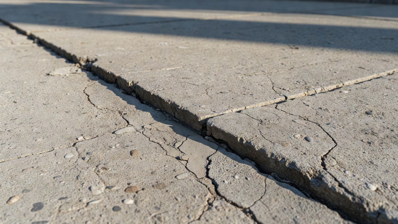
Faulting is defined as the vertical displacement or difference in elevation across a transverse joint or crack in a jointed portland cement concrete pavement (JPCP). In the FHWA Distress Identification Manual for the Long-Term Pavement Performance Program (Fifth Revised Edition, FHWA-HRT-13-092), faulting is classified under Miscellaneous Distress as distress type number 12: “Faulting of Transverse Joints and Cracks,” measured in millimeters. The classification places faulting alongside blowups, lane-to-shoulder dropoff, lane-to-shoulder separation, patch deterioration, and water bleeding/pumping as miscellaneous distress types that do not fit neatly into cracking, joint deficiency, or surface defect categories. Faulting specifically refers to a condition where the slab on the approach side of a joint sits higher than the slab on the leave side, creating what pavement engineers call a “step” or “lip” that vehicles must climb as they travel across the joint. This step is felt as a bump by vehicle occupants and measured as a positive faulting value when the approach slab is higher. When the leave slab is higher than the approach slab, the reading is negative, though positive faulting is far more common due to the predominant mechanism of pumping-driven erosion.
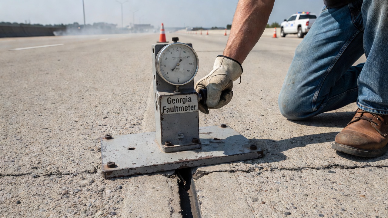
The primary instrument used for field measurement of faulting in the FHWA LTPP program is the Georgia Faultmeter (GFM). Developed by the Georgia Department of Transportation Office of Materials and Research, this lightweight device weighs approximately 3.2 kg and employs a Linear Variable Differential Transformer (LVDT) to determine the positive or negative elevation difference at a joint or crack. The measurement procedure is standardized: the legs of the GFM’s base are set on the leave slab in the direction of traffic, with the joint centered between guidelines marked on the side of the meter. The measuring probe contacts the approach slab, and vertical movement of this probe is transmitted to the LVDT, producing a digital readout in millimeters. A positive reading indicates the approach slab is higher; a negative reading indicates the leave slab is higher. At each joint or crack, three measurements are taken, and a representative value derived from these three readings is entered into the LTPP Pavement Performance Database (PPDB). The manual measurement process, while accurate, requires traffic control, lane closures, safety measures, and dedicated personnel. Measurement errors can arise from vertical binding of the probe rod, non-linearity of the LVDT when approach and leave slabs are not on the same plane, weak batteries, improper calibration, and data entry errors with a reading resolution of approximately ±1 mm.
The LTPP program has developed an Automated Faulting Measurement (AFM) algorithm to reduce reliance on manual measurements. Using 25-mm interval longitudinal profile data collected by high-speed inertial profilers (HSIP) such as the ICC MDR 4086L3, the AFM algorithm identifies transverse joint locations and determines faulting at each joint automatically. The algorithm addresses several challenges inherent in automated joint detection, including varying joint spacing that complicates pattern search routines, the presence of cracks that produce false positives, spalled joints that create elevation valleys resembling true joints, joints filled with sealants or incompressible materials that mask the joint signature, closed joints due to slab thermal expansion, skewed joints that confound pattern search algorithms, and distance measuring instrument drift. Two existing AASHTO R 36-12 automated faulting methods — ProVAL (developed by the Transtec Group using 25-mm interval profiler data) and PaveSuite (developed by FDOT using 20.7-mm interval HSIP data) — have been evaluated alongside the LTPP AFM algorithm. The transition to automated faulting measurement eliminates lane closures and reduces personnel exposure to traffic, while providing continuous faulting data across entire pavement sections rather than discrete manual point measurements.
The dominant mechanism responsible for faulting in jointed concrete pavements is pumping — the hydraulic ejection of water and fine material from beneath concrete slabs under the action of repeated heavy wheel loads. Three necessary conditions must be present for pumping to initiate: the presence of free water beneath the slab, a fine-grained or erodible base, subbase, or subgrade material, and frequent slab deflections under heavy axle loads that pressurize the trapped water. When a loaded wheel approaches and crosses a transverse joint, the approach slab deflects downward, compressing any water present in the void space between the slab bottom and the underlying base. This pressurized water is forced laterally toward the joint opening and onto the pavement surface, carrying with it suspended fine particles of the base, subbase, or subgrade material. Over thousands of load repetitions, this process progressively removes supporting material from beneath the approach slab corner while depositing it under the leave slab. The net result is a loss of support under the approach slab — causing it to settle — and a buildup of material under the leave slab — causing it to rise relative to the approach side. This differential vertical movement is what produces the characteristic faulted step at the joint.
The erosion of base and subbase materials is central to the faulting mechanism. Studies documented in the Transportation Research Record have shown that fines are removed from unstabilized materials primarily through pore water pressure buildup during load application. The erodibility of the base material, the rate of water ejection, the magnitude of slab deflection, and the number of load repetitions all influence the rate at which faulting develops. Cement-treated bases, lean concrete bases, and asphalt-treated permeable bases exhibit significantly lower erosion rates than untreated granular bases. Aggregate interlock at joints — the natural shear transfer mechanism in undoweled pavements — deteriorates as erosion progresses, which in turn increases slab deflections and accelerates pumping, creating a self-reinforcing cycle of deterioration. Laboratory studies at the University of Texas and field observations from the LTPP program have confirmed that faulting rates in undoweled JPCP can be three to five times greater than in doweled pavements with the same base and traffic conditions.
Differential settlement of the subgrade represents a distinct but related cause of faulting, particularly at locations where soil conditions change abruptly beneath the pavement, such as at culvert crossings, bridge approaches, or transitions between cut and fill sections. Differential settlement differs from pumping-induced faulting in that it results from long-term consolidation or compression of underlying soils rather than the hydraulic transport of material. However, the two mechanisms often interact: differential settlement creates small initial elevation differences that allow water to pond and infiltrate at joints, which then initiates pumping. Additionally, curling and warping of concrete slabs due to thermal and moisture gradients contribute to faulting development. During daytime hours, the top of the slab is warmer than the bottom, causing the slab edges to curl downward and increasing load transfer demands at the joint. At night, the temperature gradient reverses, and slab corners curl upward, leaving the slab supported primarily at its center and increasing the potential for corner deflections under load. These daily temperature cycles subject the joint and the underlying base to cyclic stresses that accelerate erosion.
The FHWA research publication Long-Term Pavement Performance Automated Faulting Measurement (FHWA-HRT-14-092) identifies the combination of factors that contribute to faulting: inefficient load transfer at joints, slab pumping, slab settlements, curling and warping, and inadequate base support conditions. Faulting is not solely a structural failure but rather a distress that develops through the interaction of structural design, material properties, environmental conditions, and traffic loading over time.
The FHWA LTPP Distress Identification Manual classifies faulting as a Miscellaneous Distress (Type 12) for jointed portland cement concrete pavements, measured strictly in millimeters, without defined severity levels. This distinguishes faulting from cracking distresses such as corner breaks, longitudinal cracking, and transverse cracking, which have Low, Moderate, and High severity classifications. For faulting, the raw measurement value is recorded directly in the PPDB. However, faulting severity thresholds are implicitly embedded in the classification of related distresses. For corner breaks (Distress Type JCP 1), a corner break is classified as Moderate severity when faulting of the crack or joint is less than 13 mm, and High severity when faulting equals or exceeds 13 mm. For longitudinal cracking (Distress Type JCP 3), faulting thresholds are set at less than 13 mm for Moderate severity and 13 mm or greater for High severity. For transverse cracking (Distress Type JCP 4), the thresholds are tighter: faulting up to 6 mm corresponds to Moderate severity, while faulting of 6 mm or greater corresponds to High severity. These embedded thresholds provide a practical framework for evaluating when faulting has reached a level that, in conjunction with cracking, warrants major rehabilitation.
Within the LTPP data collection protocol, faulting measurements are recorded at every transverse joint and crack on JCP test sections during each monitoring cycle. The longitudinal profile data collected by HSIP along the left wheelpath, right wheelpath, and center of the lane since 1995 provides a continuous record from which both IRI and automated faulting values can be derived. The LTPP program’s AFM algorithm processes this profile data to compute faulting at each detected joint, comparing favorably with manual GFM measurements. Research documented in FHWA-HRT-14-092 demonstrates that the correlation between GFM and AFM faulting values is strongest on sections with well-defined joints and minimal surface distress. Sections with extensive spalling, patching, or crack sealing present greater challenges for automated detection due to the difficulty of distinguishing between true joint signatures and spall-related elevation valleys.
The LTPP program’s standardized approach has enabled nationwide analysis of faulting progression as a function of design variables, traffic loading, climate, and subgrade type. This longitudinal dataset — spanning over three decades for some test sections — has been instrumental in calibrating the faulting prediction models used in the AASHTOWare Pavement ME Design software. The ME Design faulting model for JPCP predicts monthly incremental faulting as a function of the number of axle load applications, the pavement structural properties, the load transfer efficiency, the base erodibility, and the climatic conditions. The model distinguishes between doweled and undoweled pavements, with doweled sections exhibiting significantly lower predicted faulting over the design life due to the maintenance of high load transfer efficiency through mechanical dowel action.
Load transfer efficiency (LTE) at transverse joints is the percentage of a wheel load applied on one side of the joint that is transferred to the adjacent slab through shear action. In jointed concrete pavements, LTE can be provided by aggregate interlock (the natural shear resistance between fractured aggregate faces along the crack beneath the joint), by mechanical steel dowel bars, or by a stabilized base that bridges the joint. LTE is measured using a Falling Weight Deflectometer (FWD) or Heavy Weight Deflectometer (HWD), with sensors positioned on both sides of the joint. The deflection on the unloaded slab divided by the deflection on the loaded slab, expressed as a percentage, defines LTE. A joint with 100 percent LTE transfers the entire load; a joint with 0 percent LTE transfers nothing. Typical acceptance criteria for new construction specify minimum LTE values of 70 to 80 percent, while values below 50 percent generally indicate significant joint deterioration and accelerated faulting development.
Faulting and LTE share a reciprocal cause-and-effect relationship. When LTE is high, slab deflections at the joint are minimized, which reduces the pumping action and erosion of base materials that cause faulting. When LTE degrades — either because aggregate interlock deteriorates due to crack widening or because dowel bars loosen within the concrete — slab deflections increase. Increased deflections amplify the hydraulic pumping action, accelerating erosion and faulting. As faulting increases, the geometry of the joint changes, potentially degrading LTE further by creating a step that forces the dowel bars to act in bending rather than pure shear, or by opening the joint wider and reducing aggregate interlock. This feedback loop explains why undoweled JPCP sections with initially good aggregate interlock can experience rapidly accelerating faulting once erosion begins.
Research published by the National Center for Pavement Preservation and documented in FHWA reports has quantified the strong correlation between LTE and faulting. Studies show that a 10 percent decrease in LTE corresponds to an approximate 20 to 30 percent increase in the rate of faulting development in undoweled pavements. In doweled pavements, the relationship is less direct because the steel dowels maintain positive load transfer even after significant base erosion has occurred. However, once dowel looseness develops — often detectable as a characteristic “hollow” sound during FWD testing or visible as polished rings on extracted dowels — faulting typically progresses rapidly because the loosened dowel provides reduced shear resistance and allows the approach slab to pump and settle.
Dowel bar diameter is the single most important design variable controlling LTE and, consequently, faulting. A parametric finite element study published in the journal Buildings (MDPI, 2024) found that increasing the dowel bar diameter yields approximately a 3 percent increase in LTE. Conversely, increasing the joint opening between slabs leads to an approximate 2.1 percent decrease in LTE. Standard dowel diameters range from 25 mm (1 inch) for light-traffic roads to 38 mm (1.5 inches) for interstate highways, with 50 mm (2 inches) dowels specified for some heavy industrial and port pavements. The AASHTO 1993 design guide specifies dowel diameter as a function of slab thickness, with the general rule that the dowel diameter should be one-eighth of the slab thickness. Proper dowel alignment during construction is essential: misaligned dowels that lock the joint against horizontal movement can cause cracking and spalling, while dowels that are too loose or too tight in the concrete can reduce LTE.
Faulting degrades ride quality by introducing a periodic vertical discontinuity into the longitudinal pavement profile. Every time a vehicle axle crosses a faulted joint, the suspension experiences an impulse that contributes to the overall roughness perceived by the vehicle occupants. The International Roughness Index (IRI) — the globally standardized measure of pavement roughness expressed in meters per kilometer (m/km) or inches per mile (in/mi) — captures the cumulative effect of all surface irregularities on the response of a standardized quarter-car simulation. Faulting directly increases IRI because the step at each joint adds to the accumulated suspension displacement over the length of the section. Research published by the FHWA in Relating Ride Quality and Structural Adequacy for Pavement Rehabilitation and Management demonstrates a strong linear correlation between the rate of change in faulting values and the rate of change in IRI on JPCP. On sections with transverse joint spacing of 4.6 meters (15 feet), faulting values of 2.5 mm at every joint contribute approximately 0.5 m/km (32 in/mi) to the total IRI, whereas faulting of 5 mm at every joint contributes approximately 1.0 m/km (63 in/mi).
The Present Serviceability Index (PSI) — a 0-to-5 scale developed during the AASHO Road Test (1958-1960) — remains the basis for pavement design and rehabilitation decisions in the United States. PSI is derived from physical measurements of roughness, cracking, patching, and rutting (for flexible pavements) or faulting and cracking (for rigid pavements). The PSI equation for rigid pavements incorporates the mean joint faulting as a direct input variable: higher faulting values reduce the computed PSI. A PSI of 5.0 represents a perfect pavement; a PSI of 2.5 represents the terminal serviceability level at which major rehabilitation is required. The relationship between faulting and PSI is approximately linear in the range of faulting commonly encountered in service, with each additional millimeter of mean joint faulting reducing PSI by approximately 0.05 to 0.10 units, depending on the specific equation form and the contribution of other distresses.
Threshold values derived from field studies and user surveys establish actionable faulting limits for pavement management. Faulting becomes noticeable to vehicle occupants at approximately 2.5 mm (0.1 inch) average faulting across a pavement section. At 4 mm (0.15 inch) average faulting, ride quality has degraded sufficiently that diamond grinding or other rehabilitation measures should be considered. The FHWA Guide for Diamond Grinding (2001) and subsequent updates identify faulting as a primary candidate distress for diamond grinding treatment, which can restore pavement smoothness by mechanically removing the faulted step. The economic implications of faulting-induced roughness are significant: increases in IRI of 1 m/km have been correlated with increases in vehicle operating costs of approximately 2 to 5 percent for heavy trucks, encompassing fuel consumption, tire wear, suspension maintenance, and cargo damage. Over the design life of a major highway carrying 20,000 vehicles per day, the cumulative user cost penalty of uncontrolled faulting can amount to tens of millions of dollars.
IRI thresholds for pavement condition ratings provide operational guidance. According to FHWA standards, an IRI less than 1.50 m/km (95 in/mi) corresponds to a “Good” rating, IRI between 1.50 and 2.68 m/km (95-170 in/mi) to “Fair,” and IRI above 2.68 m/km (170 in/mi) to “Poor.” On heavily faulted JPCP sections, the contribution of faulting alone can push a pavement from Fair to Poor, triggering mandatory rehabilitation under federal and state pavement management policies. This direct financial consequence of faulting — combined with the strong public perception of smoothness as a proxy for road quality — has made faulting control a central objective of concrete pavement design, construction, and preservation practice.
Faulting on airport concrete runways presents a distinct set of performance, safety, and inspection considerations that differentiate it from highway faulting. The consequences of even small vertical displacements are amplified at aircraft operating speeds: a faulted joint that produces a barely perceptible bump in a passenger car at 100 km/h becomes a significant impact at aircraft touchdown speeds of 240 to 290 km/h (130 to 160 knots). The FAA Advisory Circular 150/5320-6G (Airport Pavement Design and Evaluation) and ICAO standards establish tighter tolerances for runway surface deviations than for highway pavements. Vertical deviations at joints must be closely monitored because they can trigger nose gear oscillations known as “shimmy,” accelerate landing gear fatigue, and — in severe cases — contribute to loss of directional control during the critical takeoff roll.
The loading environment on airport runways differs fundamentally from highways. Aircraft apply fewer load repetitions — a major hub airport might log 1,000 to 2,000 daily departures compared to tens of thousands of truck axle passes on an interstate — but each aircraft load is dramatically heavier. A fully loaded Boeing 777-300ER applies approximately 34 tonnes per main landing gear strut, distributed through a six-wheel bogie, while a fully loaded Boeing 747-8 applies approximately 30 tonnes per body gear strut and 22 tonnes per wing gear strut. These concentrated loads produce deeper stress influence zones within the pavement structure, potentially mobilizing water and erodible material at greater depths than highway loads. Airport concrete pavements are accordingly designed with thicker slabs — typically 350 to 500 mm (14 to 20 inches) — and robust stabilized base layers to resist the heavy gear loads and minimize the deflections that drive pumping and faulting.
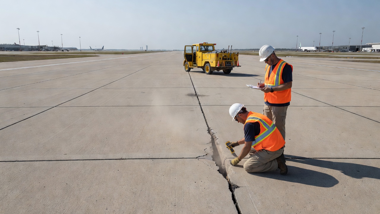
Inspection of airport runway faulting faces practical constraints not present in highway inspection. Runway closures for manual faulting measurement using devices like the Georgia Faultmeter are extremely costly in terms of operational disruption and must be scheduled within very narrow time windows, often at night or during low-traffic periods. This has driven the adoption of high-speed automated inspection technologies that can collect faulting data without runway closure, using vehicles operating at highway speeds on the runway during brief authorized access periods. The FAA’s Airport Pavement Management System (APMS) program and ICAO’s Aerodrome Pavement Management guidelines both emphasize the need for continuous, automated monitoring of runway surface condition, with faulting detection integrated into broader pavement condition index (PCI) surveys.
Faulting prevention on airport runways relies on the same fundamental principles as highway pavements — positive load transfer through dowel bars or stabilized bases, effective subsurface drainage, and erosion-resistant base materials — but the execution standards are higher. Airport runway dowel bars are typically larger in diameter and more closely spaced than highway dowels, reflecting the wider aircraft gear configurations and the need to transfer loads between slab panels of larger plan dimensions. The FAA specifies corrosion-resistant epoxy-coated dowels for all runway and taxiway joints. Joint sealant systems must be meticulously maintained to prevent water infiltration, as the consequences of pumping-induced faulting on a primary runway can necessitate emergency closures and expensive unplanned rehabilitation. Some airports have adopted stainless steel dowel bars or fiber-reinforced polymer (FRP) dowels in aggressive environments to eliminate corrosion concerns over the pavement’s 30-to-40-year design life.
The evolution of faulting detection technology has progressed from manual point measurements to continuous, high-speed, automated systems capable of surveying entire airfield and highway networks in a fraction of the time required by traditional methods. The profilograph — originally a rolling straightedge with recording capability — was the first systematic tool for measuring longitudinal profile deviations including faulting. The California Profilograph, with its 7.6-meter (25-foot) wheelbase and center sensing wheel connected to a graphic recorder, produces a profile trace from which individual bumps exceeding a specified blanking band (typically 5 mm per 0.1 km) can be counted to compute a Profile Index. While profilographs can detect faulted joints as discrete spikes in the profile trace, they do not directly measure faulting magnitude and are increasingly being replaced by inertial profilers that record true elevation data rather than relative deviations.
High-speed inertial profilers (HSIP) have become the standard tool for automated faulting measurement in both highway and airport applications. An inertial profiler uses an accelerometer mounted on the vehicle body to establish an inertial reference plane, a non-contact distance sensor (laser or infrared) to measure the distance from the vehicle to the pavement surface, and a distance measuring instrument (DMI) to record position along the pavement. By combining the vertical acceleration data — double-integrated to displacement — with the surface height measurement, the profiler computes the true pavement elevation profile at sampling intervals as fine as 1 mm and reporting intervals of 25 mm or less. The LTPP program’s AFM algorithm processes this profile data through a sequence of operations: first, potential joint locations are identified by detecting localized elevation changes exceeding a threshold; then, a region around each candidate joint is analyzed to compute the characteristic faulting at that location by fitting lines to the approach and leave slab profiles and computing the vertical offset between them. The AASHTO R 36-12 standard defines two established methods: ProVAL (Method A), which uses a 300-mm baseline and linear regression on either side of the joint, and PaveSuite (Method B), which employs a slope-detection algorithm optimized for FDOT profile data.
LiDAR (Light Detection and Ranging) technology represents the current frontier in pavement faulting detection. Mobile LiDAR systems mounted on survey vehicles emit laser pulses at rates of up to 2 million points per second, recording the three-dimensional coordinates of each reflected point with millimeter-level accuracy. The resulting dense 3D point cloud captures the full pavement surface geometry, from which faulting at joints can be extracted algorithmically. LiDAR-based faulting detection offers several advantages over profiler-based methods: it captures the full transverse profile rather than single wheelpaths, enabling detection of differential faulting across the lane width; it can simultaneously capture other pavement distresses such as rutting, cracking, and surface texture; and the dense point cloud supports retrospective analysis and algorithm refinement without requiring additional field data collection. Research published in the Journal of Infrastructure Systems and presented at Transportation Research Board annual meetings has demonstrated that LiDAR-derived faulting measurements correlate with manual GFM measurements at R² values exceeding 0.90 on well-maintained pavement surfaces. The primary limitations of LiDAR are cost and data processing requirements — a single lane-kilometer generates gigabytes of point cloud data requiring specialized software and computational resources to process.
Stereo vision systems offer a complementary approach to LiDAR for automated faulting detection. Using paired cameras mounted on a survey vehicle, stereo vision reconstructs the three-dimensional pavement surface through triangulation, similar to the principle of human depth perception. Modern implementations combine stereo cameras with Global Positioning System (GPS) modules and inertial measurement units (IMUs) for precise georeferencing. A 2024 study published in the journal Results in Engineering (Implementation of a Low-Cost Comprehensive Pavement Inspection System) demonstrated that stereo camera systems can achieve faulting detection accuracy comparable to dedicated profilers at a fraction of the equipment cost. Deep learning algorithms — particularly convolutional neural networks (CNNs) and U-Net architectures — trained on labeled datasets of pavement images and point clouds can automatically identify joint locations, classify faulting severity, and distinguish faulting from other elevation anomalies such as spalling, patching, and debris. Automated pixel-level pavement distress detection based on stereo vision and deep learning, as described in research from Monash University, integrates multi-view stereo imaging with semantic segmentation to produce comprehensive pavement condition maps that include faulting, cracking, and surface deformation in a single pass.
Effective prevention of faulting begins at the pavement design stage with three interdependent elements: positive load transfer through dowel bars, erosion-resistant stabilized bases, and comprehensive subsurface drainage. Dowel bars are the most direct and effective countermeasure against faulting. By providing positive mechanical shear transfer across the joint, dowels maintain high LTE throughout the pavement’s service life, dramatically reducing slab deflections and the pumping action that drives faulting. The diameter, length, spacing, and embedment depth of dowel bars are all critical design parameters. Standard practice for highway pavements specifies smooth, epoxy-coated round steel bars spaced at 300 mm (12 inches) center-to-center across the transverse joint. Dowel length must be sufficient to transfer shear while allowing the joint to open and close with thermal expansion and contraction — typically 460 mm (18 inches) for standard 4.6-meter (15-foot) joint spacing. Dowel bars must be placed at the mid-depth of the slab (±20 mm tolerance) and aligned parallel to both the pavement surface and the centerline of the lane (±10 mm horizontal and vertical). Misaligned dowels that restrain joint movement cause adjacent concrete to crack and spall, while loose dowels provide reduced LTE and may worsen rather than prevent faulting. Dowel bar baskets or mechanical inserters (DBIs) are used during construction to set the bars at the correct position and alignment before the concrete is placed.
Stabilized bases provide a firm, erosion-resistant platform beneath the concrete slab that resists the hydraulic scouring action of pumping. The American Concrete Pavement Association and FHWA identify cement-treated bases (CTB), lean concrete bases (LCB), and asphalt-treated permeable bases (ATPB) as effective stabilized base options. Cement-treated bases with cement contents of 3 to 5 percent by weight develop sufficient strength and cohesion to resist erosion while remaining flexible enough to accommodate slab movements. Lean concrete bases, with compressive strengths of 5 to 10 MPa (700 to 1,500 psi), provide the highest erosion resistance but are also the most expensive. Asphalt-treated permeable bases combine drainage and erosion resistance in a single layer: the open-graded aggregate skeleton stabilizes the base against erosion while the interconnected voids allow water to drain laterally to edge drains. The LTPP data has conclusively demonstrated that JPCP sections constructed on stabilized bases develop faulting at rates 40 to 60 percent lower than those on untreated granular bases, all other factors being equal. The performance differential is most pronounced on high-traffic routes and in wet climates where the pumping potential is greatest.
Subsurface drainage addresses the root cause of pumping by removing the water that makes pumping possible. A properly designed pavement drainage system includes a permeable drainage layer (either a treated permeable base or a separate open-graded drainage blanket), longitudinal edge drains with perforated collector pipes, and positive outlet structures that discharge water to daylight or storm sewers. The drainage layer must have a permeability of at least 300 m/day (1,000 ft/day) to rapidly convey water to the edge drains, and it must be protected from clogging by a geotextile separator or a graded aggregate filter. The edge drains must be placed at a depth that allows gravity flow and must be regularly inspected and maintained — a clogged edge drain provides no benefit and may actually trap water beneath the pavement. Research by the FHWA and state DOTs has shown that JPCP sections with functioning edge drains develop faulting at rates 30 to 50 percent lower than undrained sections in similar environments. In regions with high water tables, the drainage system may need to include underdrains that lower the groundwater level below the pavement structure, as water that rises from below is just as damaging as water that infiltrates from above.
Joint sealing is a supplementary prevention measure that limits the amount of surface water entering the pavement structure through the joints. While joint sealant does not directly prevent faulting — water enters the pavement structure through cracks, shoulders, and subgrade capillary action regardless of joint sealing — well-maintained joint seals reduce the volume of water available for pumping and keep incompressible materials (sand, stones) out of the joint reservoir, preventing pressure-related spalling and blowups. Hot-pour sealants, silicone sealants, and preformed compression seals are used depending on climate, traffic, and agency preference. Joint sealant must be periodically replaced as it oxidizes, embrittles, and loses adhesion — typical sealant service lives range from 5 to 12 years depending on material and environment.
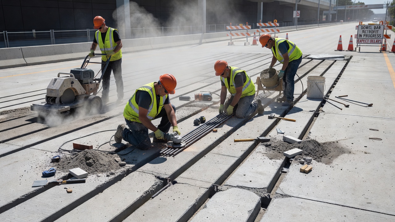
When faulting has already developed on an in-service pavement, two complementary rehabilitation techniques — dowel bar retrofit (DBR) and diamond grinding — can restore load transfer, ride quality, and structural integrity without full slab replacement. DBR is the process of installing dowel bars across existing joints or cracks in a jointed concrete pavement to restore positive load transfer. The procedure begins with sawing slots approximately 100 to 150 mm (4 to 6 inches) wide, 300 to 400 mm (12 to 16 inches) long, and extending to the mid-depth of the slab across each wheelpath on both sides of the joint. The slots are cleaned of concrete debris and inspected for base condition — if significant base erosion is evident, pressure grouting or mudjacking to fill the voids beneath the slab should be performed before the dowels are placed. Epoxy-coated steel dowel bars, typically 32 mm or 38 mm (1.25 or 1.5 inches) in diameter and 460 mm (18 inches) long, are positioned in the slots with end caps or debonding agents applied to one end to allow the joint to move freely. The dowels must be set at the correct elevation and alignment using chairs or positioning brackets, then the slots are filled with a non-shrink, high-early-strength cementitious grout or a polymer concrete. After a curing period of 2 to 4 hours for rapid-set materials, the pavement can be reopened to traffic.
DBR has been used extensively in the United States since the late 1980s, with the Washington State Department of Transportation serving as the lead state in developing and refining the technique. The FHWA Tech Brief on DBR documents performance data showing that properly executed DBR restores LTE to 70 to 90 percent and reduces subsequent faulting development by 60 to 80 percent compared to untreated undoweled joints. The longevity of DBR depends critically on the condition of the existing slab and base: DBR should not be installed over severely deteriorated base material, as the dowels require sound concrete and adequate base support to function properly. Locations with active pumping or significant base loss should receive base stabilization treatment before or concurrent with DBR. DBR is appropriate for faulting magnitudes between 3 mm and 12.5 mm (0.125 to 0.5 inches). Below 3 mm, faulting does not significantly degrade ride quality and does not justify the cost of retrofit. Above 12.5 mm, the underlying base and subgrade damage is typically too extensive for effective DBR, and full-depth reconstruction is warranted.
Diamond grinding is a surface restoration technique that removes a thin layer of concrete from the pavement surface using closely spaced, diamond-impregnated saw blades mounted on a self-propelled grinding machine. The blades are typically spaced 2.5 to 3.2 mm (0.10 to 0.125 inches) apart and cut grooves 3 to 5 mm deep into the surface, producing a characteristic corduroy texture. The primary purpose of diamond grinding is to eliminate joint faulting by removing the elevated approach slab surface down to the level of the leave slab, restoring a smooth, continuous profile. Diamond grinding also removes minor surface irregularities, restores transverse drainage by reestablishing cross-slope, and provides a quiet, skid-resistant surface texture. FHWA’s Concrete Pavement Rehabilitation — Guide for Diamond Grinding (2001) specifies that grinding must achieve a Profile Index of less than 160 mm/km (10 in/mi) using a California Profilograph with a 5-mm (0.2-inch) blanking band — a standard that equates to an IRI of approximately 1.6 m/km (100 in/mi) or better.
When DBR and diamond grinding are combined, they provide a comprehensive faulting rehabilitation strategy. DBR restores the underlying load transfer mechanism to prevent future faulting development, while diamond grinding corrects the existing surface faulting and roughness. Research published by the International Grooving and Grinding Association and the FHWA demonstrates that DBR followed by diamond grinding can extend the service life of a faulted concrete pavement by 15 to 20 years, making it one of the most cost-effective concrete pavement preservation treatments available. Long-term performance data from LTPP Specific Pavement Studies (SPS) experiments show that diamond-ground JPCP sections with stabilized bases, edge drains, and adequate joint spacings maintain lower faulting rates after grinding compared to sections without these features, confirming that grinding addresses the symptom (surface faulting) while DBR and good base/drainage design address the cause (inadequate load transfer and pumping).
The cost-effectiveness of faulting rehabilitation must be evaluated against the alternative of reconstruction. A typical DBR and diamond grinding project costs approximately $25 to $45 per square meter ($3 to $5 per square foot) in 2024 dollars, compared to $80 to $150 per square meter ($10 to $15 per square foot) for full-depth reconstruction. This cost differential, combined with the shorter construction duration (days versus weeks per lane-kilometer) and reduced traffic disruption, makes DBR and grinding the preferred treatment for faulted concrete pavements where the underlying slab and base remain structurally adequate.
Automated pavement inspection with LiDAR and stereo vision technology detects faulting at millimeter-level precision across highways and airport runways without lane closures.
Load transfer devices (dowel bars, tie bars, aggregate interlock, keyed joints) transfer wheel loads across joints and cracks in concrete pavements, preventing ...
Joint spalling is the cracking, breaking, or chipping of concrete slab edges at transverse or longitudinal joints in PCC pavements. It occurs when incompressibl...
Pumping is the ejection of water and fine subgrade or subbase material through pavement joints, cracks, or edges under passing wheel loads, progressively erodin...