Fiber-Reinforced Concrete (FRC) contains distributed short fibers (steel, synthetic macro, glass, carbon, natural) to control cracking, improve toughness, and reduce joint spacing in pavements. Covers fiber types, dosage, mixing, performance benefits, and inspection of FRC pavements.
What is Fiber-Reinforced Concrete (FRC)?
Fiber-Reinforced Concrete (FRC) is a composite material consisting of hydraulic cement, fine and coarse aggregates, water, admixtures, and discrete reinforcing fibers uniformly distributed throughout the matrix. Unlike conventional concrete reinforced with continuous steel bars or welded-wire fabric, FRC derives its post-cracking tensile capacity from thousands of short fibers per cubic meter that bridge cracks at the microstructural level. The fibers begin to function structurally when the concrete matrix starts to crack — at that point, load transfers from the concrete to the fibers, providing ductility, toughness, and residual load-carrying capacity that plain concrete lacks.
FRC is classified under ASTM C1116/C1116M — Standard Specification for Fiber-Reinforced Concrete and Shotcrete — into four types: Type I (steel fiber-reinforced concrete, conforming to ASTM A820/A820M), Type II (glass fiber-reinforced concrete, conforming to ASTM C1666), Type III (synthetic fiber-reinforced concrete, conforming to ASTM D7508/D7508M for polyolefin fibers), and Type IV (natural fiber-reinforced concrete, conforming to ASTM D7357 for cellulose fibers). Each classification addresses specific fiber materials, geometries, and performance requirements.
The historical use of fibers in cementitious materials dates back to biblical times when straw and horsehair were added to sun-dried clay bricks and mortar. Modern FRC technology emerged in the 1960s with pioneering research by Romualdi and Batson on steel fiber reinforcement, followed by the development of synthetic fibers in the 1970s. Today, FRC is specified for a wide range of applications including pavements and slabs-on-ground, composite metal decks, tunnel linings and shotcrete, bridge decks, precast elements, airport pavements, and industrial flooring systems.
{{}}
Fiber Types in FRC Pavements
Steel Fibers (ASTM A820/A820M Types I–V)
Steel fibers are the most widely used fiber type for structural pavement applications. They are manufactured from carbon steel and classified into five types under ASTM A820/A820M. Type I — Cold-Drawn Wire fibers are produced by drawing steel wire through dies, giving them the highest tensile strength (typically 1,100–2,500 MPa). Type II — Cut Sheet fibers are sheared from steel sheets and have a rectangular cross-section. Type III — Melt Extracted fibers are produced by a melt extraction process and are rarely available in the commercial marketplace. Type IV — Mill Cut fibers are cut from steel scrap and have irregular geometries. Type V — Modified Cold-Drawn Wire fibers are cold-drawn with subsequent mechanical deformation to enhance anchorage.
The most common steel fiber geometry for pavements is hooked-end, where both ends are bent into hooks to provide mechanical anchorage within the concrete matrix. Other geometries include crimped (continuously undulated along the length), flat-end (with deformed or enlarged ends), and straight (with no end deformation). Hooked-end fibers have demonstrated superior pullout resistance, requiring 2–4 times more energy to extract than straight fibers of equivalent length and diameter.
Key properties of steel fibers include: length of 30–60 mm (1.2–2.4 in), aspect ratio (length divided by equivalent diameter) of 40–80, tensile strength of 400–2,500 MPa (58–363 ksi), elastic modulus of approximately 210 kN/mm² (30,000 ksi), and density of 7.8 g/cm³. The high elastic modulus — identical to that of steel reinforcing bars — ensures that steel fibers activate immediately upon crack formation, providing effective stress transfer across cracks.
For pavement applications, steel fibers are dosed at 20–30 kg/m³ (34–51 lb/yd³), equivalent to 0.25–0.38% by volume. For thin overlays, dosages as low as 14.8 kg/m³ (25 lb/yd³) can provide adequate temperature and shrinkage crack control. The Steel Deck Institute (SDI) specifies minimum steel fiber dosages for crack control in composite slab applications. ACI 544 recommends a minimum of 25 kg/m³ (42 lb/yd³) for structural applications.
Macro-Synthetic Fibers
Macro-synthetic fibers (also called structural synthetic fibers) are manufactured from polypropylene, polyethylene, or polyolefin blends. They have a diameter of 0.3 mm or greater (0.012 in minimum), distinguishing them from micro-synthetic fibers. Typical lengths are 38–60 mm (1.5–2.4 in). Their tensile strength ranges from 165–600 MPa (24–87 ksi), and their elastic modulus of 1–8 kN/mm² (145–1,160 ksi) is significantly lower than steel — approximately 1–4% of steel’s stiffness.
Despite the lower modulus, macro-synthetic fibers provide equivalent residual strength to steel fibers at roughly 1/5 to 1/3 the mass dosage due to their lower density (0.90–0.91 g/cm³), which yields a much higher fiber count per kilogram. For the same mass dosage, approximately 8–9 times more synthetic fibers exist per cubic meter compared to steel fibers, creating a denser fiber network across potential crack planes.
Typical dosages for pavements range from 4–9 kg/m³ (6.7–15.2 lb/yd³). For slabs-on-ground, dosages of 3–8 kg/m³ (5–13.5 lb/yd³) provide post-crack residual strength equivalent to welded-wire fabric. For pavement overlays, 0.32–0.48% by volume has been confirmed effective by research conducted by Roesler and colleagues at the University of Illinois.
Macro-synthetic fibers offer critical advantages for airport pavements and bridge decks where corrosion is a concern. They do not rust, produce no surface staining, and are resistant to chemical attack. They are also lighter, reducing transportation costs, and are safer for handling during construction.
Polypropylene Micro-Fibers
Micro-fibers have a diameter less than 0.3 mm (0.012 in) and lengths of 3–20 mm (0.12–0.75 in). They are available in monofilament (individual single fibers) or fibrillated (fibers that split into multiple filaments during mixing) configurations. Their primary function is plastic shrinkage crack control during the first 24 hours after placement.
At typical dosages of 0.6–0.9 kg/m³ (1.0–1.5 lb/yd³), micro-fibers reduce plastic shrinkage cracking by providing a three-dimensional reinforcement network that distributes tensile stresses from restrained shrinkage. They do not provide significant post-crack structural capacity at these dosages. However, fibrillated micro-fibers at minimum dosages of 1.5 lb/yd³ (0.9 kg/m³) per ASTM D7508 can be used to replace light-gage welded-wire reinforcement (WWR) for temperature and shrinkage crack control in slabs-on-ground, up to 10-gage (W1.6/W1.6).
Micro-fibers also provide benefits for impact resistance, fire spalling protection, and abrasion resistance. They are commonly used in conjunction with macro-fibers in blended fiber systems, where micro-fibers address early-age cracking and macro-fibers provide long-term structural performance.
Glass Fibers (AR-Glass)
Alkali-resistant (AR) glass fibers contain at least 16% zirconium dioxide (ZrO₂) to resist the alkaline environment of cement hydration. They have a tensile strength of approximately 2,500 MPa (363 ksi) and an elastic modulus of 80 kN/mm² (11,600 ksi). Typical lengths are 6–25 mm (0.25–1.0 in). Density is 2.7 g/cm³.
Glass fiber-reinforced concrete (GFRC) is used primarily in precast architectural panels, decorative overlays, and thin-shell elements rather than structural pavements. Glass fibers are susceptible to embrittlement over time in alkaline environments and require specialized mix designs. In pavement applications, AR-glass fibers have been used experimentally in thin overlay systems.
Carbon Fibers
Carbon fibers offer the highest tensile strength (3,000–6,000 MPa) and highest elastic modulus (200–400 kN/mm²) of any commercially available fiber type. They are used in ultra-high performance concrete (UHPC) and specialized applications where extreme performance justifies their high cost (typically 15–50 kg/m³ for high-performance concretes). For general pavement applications, carbon fibers remain cost-prohibitive.
Natural Fibers (Cellulose, Sisal, Coir, Bamboo)
Natural fibers are classified under ASTM D7357 (Standard Specification for Cellulose Fibers for Fiber-Reinforced Concrete). Cellulose fibers at dosages of 0.3–0.9 kg/m³ provide plastic shrinkage control. Other natural fibers (sisal, coir, bamboo) have been used in low-cost housing and rural road pavements but exhibit variable performance, susceptibility to biological degradation, and lower durability than manufactured fibers.
Fiber Mechanisms in Concrete
Crack Bridging
Crack bridging is the fundamental mechanism by which fibers enhance concrete performance. When a tensile crack initiates in the concrete matrix, fibers that cross the crack plane continue to transmit stress across the opening. The fibers develop bond stresses along their embedded length on both sides of the crack. The bond is a combination of:
Adhesion — chemical bonding between the fiber surface and hydration products
Friction — mechanical resistance as the fiber begins to slide within the matrix
Mechanical anchorage — physical interlock provided by hooked ends, crimps, embossing, or other deformations
The efficiency of crack bridging depends on fiber aspect ratio (length/diameter), fiber tensile strength, anchorage geometry, concrete compressive strength, and fiber orientation relative to the crack plane. Higher aspect ratios increase the surface area available for bond development. Well-anchored fibers (hooked-end, crimped) can develop 2–3 times the pullout resistance of straight fibers of equivalent geometry.
Post-Crack Toughness and Ductility
Unlike plain concrete — which exhibits brittle failure with abrupt loss of load capacity at first crack — FRC demonstrates ductile post-crack behavior. After the matrix cracks, the fibers continue to carry load across the crack, preventing uncontrolled crack opening. The concrete does not separate into discrete pieces but remains integral, held together by the fiber network.
Toughness is the energy absorption capacity of FRC, measured as the area under the load-deflection curve from flexural testing (ASTM C1609). It represents the total work required to deflect a fiber-reinforced beam to a specified deflection. Toughness values are reported in Joules for round panel tests (ASTM C1550) or as equivalent flexural strength ratios for beam tests.
The load-deflection response of FRC typically shows: (1) an initial linear-elastic region where both concrete and fibers share load, (2) a first-crack peak at the modulus of rupture (MOR), (3) a post-crack load drop, and (4) a plateau or gradually descending tail where fibers control crack opening by progressively pulling out. The shape of this tail — whether flat (deflection-softening) or rising (deflection-hardening) — depends on fiber type, dosage, and concrete properties. Steel fibers generally produce a higher post-crack plateau than synthetic fibers at equivalent volume fractions.
Shrinkage Crack Control
FRC controls shrinkage cracking through crack-width limitation rather than shrinkage reduction. Fibers do not significantly reduce the magnitude of drying shrinkage — they control how shrinkage-induced stresses are distributed. By bridging micro-cracks as they form during the first 24 hours (plastic shrinkage) and during drying (long-term shrinkage), fibers prevent individual cracks from widening and propagating.
The fiber spacing theory (Romualdi and Batson, 1963) states that the effectiveness of fibers in controlling cracks is inversely proportional to the spacing between fibers. When fibers are closely spaced, they intercept micro-cracks before they coalesce into visible macro-cracks. The critical fiber spacing for effective crack control is typically less than 10–15 mm, which requires fiber counts of 5,000–15,000 fibers per kilogram for synthetic fibers or 500–2,000 fibers per kilogram for steel fibers.
Fiber Dosage and Mixing
Dosage Determination
Fiber dosage is determined based on performance requirements rather than a fixed quantity. The industry standard approach specifies a target residual strength value — typically f₁₅₀ ≥ 1.4 MPa (200 psi) at L/150 deflection per ASTM C1609 — and the fiber supplier demonstrates that their fiber at a given dosage meets or exceeds this value. This performance-based specification approach is recommended over prescriptive dosage specifications because different fiber geometries, materials, and anchorage systems achieve equivalent performance at different dosages.
Application
Steel Fiber Dosage
Macro-Synthetic Fiber Dosage
Slabs-on-ground / Pavements
20–30 kg/m³ (34–51 lb/yd³)
4–9 kg/m³ (7–15 lb/yd³)
Thin overlays (75–150 mm)
15–25 kg/m³ (25–42 lb/yd³)
3–6 kg/m³ (5–10 lb/yd³)
Industrial floors (heavy loads)
25–35 kg/m³ (42–59 lb/yd³)
5–8 kg/m³ (8–14 lb/yd³)
Shotcrete / Tunnel linings
25–40 kg/m³ (42–67 lb/yd³)
5–10 kg/m³ (8–17 lb/yd³)
Plastic shrinkage control only
Not applicable
0.6–0.9 kg/m³ (1.0–1.5 lb/yd³)
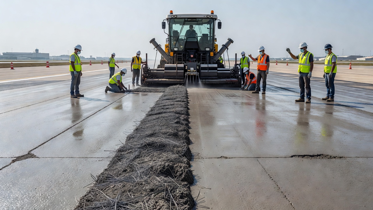
Mixing Procedures
Fibers are added during the mixing process, preferably to the wet concrete after all other ingredients (cement, aggregates, water, admixtures) have been combined. Adding fibers to dry aggregates risks fiber segregation. The mixing sequence should be:
Add fibers gradually over 30–60 seconds (not all at once)
Add remaining water and admixtures
Mix for 4–5 minutes (30–60 seconds longer than standard concrete) to ensure uniform fiber distribution
Verify fiber dispersion by visual inspection of multiple grab samples
Collated fibers (glued together in clips or bundles) are designed to disperse efficiently during mixing. The glue dissolves in the alkaline concrete environment, releasing individual fibers. This avoids the need for prolonged mixing and reduces the risk of fiber balling.
Fiber Balling — Causes and Prevention
Fiber balling occurs when fibers clump into dense spherical masses rather than dispersing uniformly. It is most likely when:
Aspect ratio exceeds 80–100 — long, thin fibers entangle more readily
Dosage exceeds 2% by volume — for steel fibers, this equates to approximately 156 kg/m³
Rapid fiber addition — dumping all fibers into one spot in the mixer
Lean mix designs — insufficient paste to coat and separate fibers
Overly dry concrete — slump below 50 mm (2 in)
Inadequate mixing time or energy
Prevention measures include: verifying fiber aspect ratio is suitable for the mixing equipment, maintaining a minimum slump of 75–125 mm (3–5 in), using high-range water reducers (HRWR) rather than increasing water content, adding fibers gradually over 30 seconds, extending mixing time, and conducting visual fiber distribution tests on fresh concrete.
FRC Performance Properties
Flexural Toughness (ASTM C1609/C1609M)
ASTM C1609 is the primary standard for evaluating the flexural performance of FRC. It uses third-point loading on a beam specimen (100×100×350 mm for the standard 4×4×14 in beam, or 150×150×500 mm for the 6×6×20 in beam) in closed-loop servo-controlled testing. The test measures load versus mid-span deflection continuously from zero through a net deflection of L/150 (span/150).
Key parameters derived from ASTM C1609 include:
f₁ (first-peak strength) — the first major peak in the load-deflection curve, approximating the modulus of rupture
P₁₅₀ and f₁₅₀ (residual load and strength at L/150) — the load and flexural stress carried by fibers at a net deflection of span/150
P₆₀₀ and f₆₀₀ (residual load and strength at L/600) — the load and flexural stress at a net deflection of span/600
Equivalent flexural strength ratio (Rₑ,₃ or Re₃) — the ratio of equivalent flexural strength (area under the curve to L/150) to first-peak strength, expressed as a percentage
The f₁₅₀ value is the most commonly specified residual strength parameter for pavement design. A minimum f₁₅₀ of 1.4 MPa (200 psi) is widely accepted for structural fiber reinforcement in slabs-on-ground. The Re₃ value provides a measure of the toughness retained after cracking — values above 30–50% are typical for well-performing FRC mixtures.
Average Residual Strength (ASTM C1399/C1399M)
ASTM C1399 measures the average residual strength (ARS) of FRC using a beam with a steel plate inserted below the specimen during initial loading to control the energy release at first crack. After cracking, the plate is removed, and the cracked beam is reloaded. ARS is the average flexural stress at four specified deflections (0.5, 0.75, 1.0, and 1.25 mm for the standard beam).
ASTM C1399 is less demanding in terms of equipment (does not require closed-loop control) but introduces greater variability due to the manual plate insertion and removal. It was originally developed for micro-fibers and is less suitable for fibers longer than 38 mm (1.5 in). ARS values are reported in MPa or psi and can be specified as project requirements.
Flexural Toughness by Round Panel (ASTM C1550/C1550M)
ASTM C1550 tests FRC toughness using a round panel (diameter 800 mm, thickness 75 mm) supported on three pivot points and loaded centrally. This test was designed to replicate typical shotcrete loading conditions and is the standard test for tunnel and mining shotcrete applications. Results are reported in Joules of energy absorbed at specific deflections (typically 5, 10, 20, and 40 mm).
For pavement applications, ASTM C1550 is less common but is sometimes used for quality control of fiber-reinforced shotcrete in slope stabilization and canal lining applications.
Impact and Fatigue Resistance
FRC exhibits significantly higher impact resistance than plain concrete. Under repeated impact loading (drop-weight tests per ACI 544), FRC can absorb 5–20 times more energy than plain concrete before failure. Fatigue resistance is also improved — FRC pavements can sustain more load repetitions at a given stress level compared to unreinforced concrete, which is critical for airport pavements subjected to millions of aircraft passes over their design life.
FRC for Pavements
Joint Spacing
The most significant advantage of FRC for pavements is the ability to extend joint spacing compared to plain jointed concrete. In plain concrete pavements, joint spacing is limited to 4.5–6 m (15–20 ft) to control natural cracking. With FRC, fibers bridging the uncut concrete restrain crack formation and limit crack width if cracks do form.
For steel fiber-reinforced concrete (SFRC) pavements, joint spacing can be extended to 6–15 m (20–50 ft) depending on fiber dosage, slab thickness, base conditions, and expected loading. Research documented in the US Army Corps of Engineers technical reports demonstrates that SFRC pavements with 0.5–1.0% fiber volume fractions can operate without joints for up to 15 m.
For macro-synthetic fiber-reinforced pavements, joint spacing of 4.5–9 m (15–30 ft) has been demonstrated. The Concrete Pavement Technology Center (CPTC) and Iowa State University research indicates that macrofibers can reduce joint frequency by 30–50% compared to plain concrete.
However, design guidance (FHWA HIF-17-012) emphasizes that joint spacing in FRC pavements must be verified through project-specific analysis and confirmed by trial sections. Extending joints too far without adequate fiber dosage can result in uncontrolled cracking.
Thickness Reduction
FRC enables modest slab thickness reductions in pavements — typically 10–20% compared to plain concrete — due to higher flexural strength and residual post-crack capacity. For industrial floors with heavy loads, this reduction is supported by ACI 360 (Design of Slabs-on-Ground) Chapter 11, which incorporates residual strength into structural calculations.
For airport pavements, the FAA does not currently provide thickness reduction credit for FRC in AC 150/5320-6G. Fibers are permitted as an additive but are not recognized for structural thickness reduction. Designers must use alternative methods (finite element analysis, ACI guidance) with FAA approval for any thickness adjustments.
Comparison with Conventional Reinforcement
FRC provides several advantages and limitations compared to traditional reinforcement:
Property
FRC
Welded-Wire Fabric (WWF)
Rebar
Placement labor
None (added during mixing)
Moderate
High
Construction time
Faster (no tying required)
Moderate
Slow
Corrosion risk
Steel fibers: low (small diameter, discontinuous)
Moderate
High
Crack distribution
Multiple tight micro-cracks
Fewer wider cracks
Few widely spaced cracks
Peak flexural strength
Same as plain concrete (fibers activate post-crack)
Higher (continuous reinforcement)
Highest
Post-crack residual strength
Moderate to high (depends on fiber dosage)
High
Very high
Fatigue resistance
Improved
Good
Good
Cover requirements
Not applicable (fibers internal)
50–75 mm required
50–100 mm required
Thickness reduction
10–20% (per ACI 360)
Minimal
Up to 40% (structural design)
FRC cannot replace primary structural reinforcement in suspended slabs, cantilevered members, or structural frames. It excels as a replacement for temperature and shrinkage reinforcement (secondary reinforcement) and is most effective when combined with appropriate joint design, subgrade preparation, and load transfer systems.
FRC for Concrete Overlays
FRC is extensively used in concrete overlays — thin slabs of concrete placed over existing pavement to restore structural capacity and ride quality. FRC overlays are classified as bonded (directly adhered to the existing surface after milling/texturing) or unbonded (separated by a bond-breaking interlayer).
Bonded FRC Overlays (Thin Whitetopping)
Bonded FRC overlays range from 75–150 mm (3–6 in) in thickness. The overlay is bonded to the existing pavement through mechanical interlock after milling and cleaning. Fibers (steel or macro-synthetic) provide:
Reduced joint spacing — joints can be spaced at 0.6–1.8 m (2–6 ft) compared to 1.8–3.7 m (6–12 ft) for non-fiber overlays
Thickness reduction — 15–30% reduction compared to plain concrete overlays at equivalent performance
Improved reflective crack control — fibers bridge reflecting cracks from the underlying pavement
Enhanced bond durability — reduced debonding at overlay interfaces
Research by the CPTC and the University of Illinois (Roesler et al.) demonstrated that high-performance macro-synthetic fibers (PP and PE blends) at 0.32–0.48% volume fractions enable joint spacing up to 1.8 m × 1.8 m in 100–150 mm bonded overlays.
Unbonded FRC Overlays
Unbonded overlays are separated from the existing pavement by a bond-breaking interlayer (typically 25–50 mm of asphalt or geotextile). These overlays are thicker than bonded overlays — typically 150–250 mm (6–10 in). FRC in unbonded overlays:
Provides load transfer across joints without the need for dowel bars (in some configurations)
Reduces joint width requirements
Improves structural continuity under heavy traffic
The CPTC MAPbrief (March 2019) notes that macrofibers in unbonded overlays may require reduced joint spacing compared to plain concrete equivalents, with typical spacing ranging from 3 to 6 m (10 to 20 ft) depending on overlay thickness and fiber dosage.
{{}}
FRC for Airport Pavements
Airport pavements present unique demands: high-intensity concentrated loads (aircraft landing gear), wide load spectra (from small general aviation to wide-body jets), dynamic and impact loads during landing, and jet blast and fuel spill exposure. FRC offers specific benefits for these conditions.
FAA Position on FRC
The FAA AC 150/5320-6G (Airport Pavement Design and Evaluation, June 2021) and AC 150/5370-10H (Standard Specifications for Construction of Airports) are the primary governing documents for US airport pavement design. These circulars do not provide a dedicated FRC design procedure. Fibers are permitted as a concrete additive but currently receive no structural credit in thickness design under FAA procedures.
Historically, the FAA has researched steel fibrous concrete for airfield pavements, with reports documented in the TRB Special Report 175 on airport pavement design. The US Army Corps of Engineers conducted field performance evaluations of SFRC airfield pavements (published as ADA172888), demonstrating that steel fibers at 0.5–1.0% volume fractions can maintain structural integrity under military aircraft loading with extended joint spacing.
Design Considerations for Airports
For airport FRC pavements, designers should:
Use ACI 360 and mechanistic-empirical methods as the structural design basis
Confirm fiber type and dosage through trial batching and ASTM C1609 verification
Provide dowel bars at contraction joints for primary runway pavements (fibers alone may not provide sufficient load transfer at aircraft loads)
Include FOD (Foreign Object Debris) evaluation — exposed fibers at the surface must be controlled through proper finishing
Verify freeze-thaw resistance (air-entrainment requirements apply to FRC as for plain concrete)
Consider the corrosion-free advantage of macro-synthetic fibers for airport pavements in marine or de-icing chemical environments
ICAO Reference
ICAO Annex 14, Volume I (Aerodromes) and Doc 9137 (Airport Services Manual) do not provide specific FRC provisions. ICAO references standard rigid pavement concepts. The Aerodrome Design Manual (Doc 9157) discusses concrete pavement thickness design using conventional methods (PCA, FAARFIELD) without FRC-specific guidance. This means FRC airport pavement design remains under the purview of national aviation authorities using local design standards.
Inspection of FRC Pavements
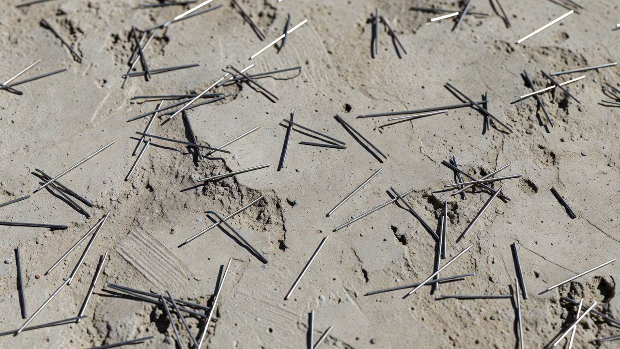
Inspecting fiber-reinforced concrete pavements requires awareness of differences from plain concrete. The discrete fibers visible at cracks and exposed surfaces are normal and expected — they are not defects unless they create FOD hazards or indicate poor consolidation.
Fiber Visibility at Surface
After finishing and curing, fibers near the surface become visible. The concrete surface may exhibit a slightly textured or “hairy” appearance from exposed fiber ends. This is inherent to FRC. Factors affecting surface fiber visibility include:
Fiber type — macro-synthetic fibers are more visible than steel fibers of equivalent dimensions due to their lighter color
Fiber dosage — higher dosages produce more surface fibers
Curing method — curing compounds can reduce fiber prominence
During inspection, surface fibers should be documented but should not automatically be classified as a pavement defect. The threshold for concern is when fibers protrude more than 2–3 mm from the surface or are easily dislodged, creating an FOD risk. ASTM D5340 (Standard Test Method for Airport Pavement Condition Index Surveys) does not specifically classify surface fiber exposure as a distress — the focus is on cracking, spalling, and structural defects.
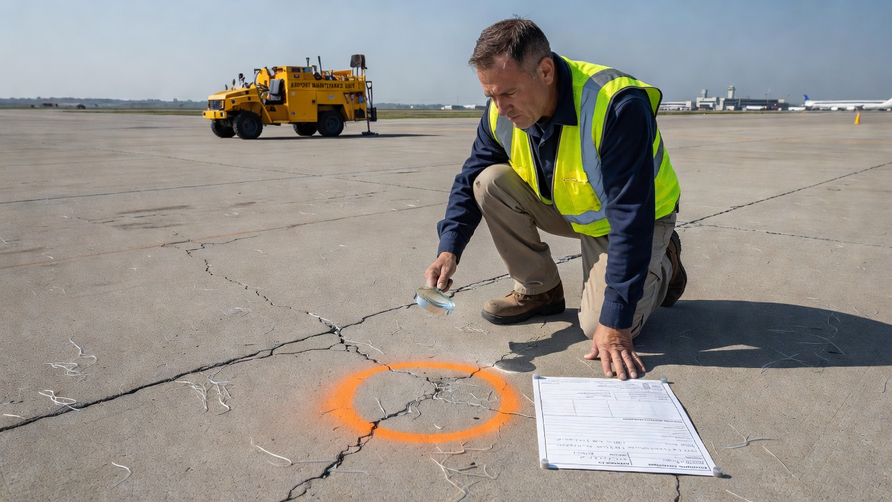
Cracking Pattern Interpretation
Cracking in FRC pavements differs from plain concrete. Tight hairline cracks (less than 0.5 mm wide) held together by fibers are typical and controlled — these represent the ductile post-crack behavior that FRC is designed to provide. The fibers bridge these cracks, maintaining load transfer and preventing water ingress.
Distinguishing between acceptable fiber-controlled cracking and structural distress requires evaluation of:
Crack width — fiber-bridged cracks are typically < 0.5 mm; wider cracks (> 1.0 mm) indicate fiber pullout has exceeded effective capacity
Crack pattern — fine random map cracking or isolated hairline cracks are typical; large continuous cracks through multiple slabs indicate structural issues
Crack faulting — vertical displacement at cracks indicates loss of load transfer
Fiber condition at crack — fibers should be intact and engaged; broken fiber ends indicate brittle failure rather than ductile pullout
Spalling along cracks — spalling indicates fiber pullout and loss of matrix integrity
Quality Control Testing During Construction
Quality control (QC) for FRC pavement construction includes:
Test
Frequency
Acceptance Criteria
ASTM C1609 beam testing
1 set of 3 beams per 50 m³ of concrete
f₁₅₀ ≥ specified value (typically ≥ 1.4 MPa)
Fiber dosage verification (wash-out test)
1 per 15 m³ or per truck for batch verification
±5% of target dosage
Visual fiber distribution
1 per 25 m³ (multiple grab samples)
Uniform dispersion, no balling
Slump (ASTM C143)
1 per 15 m³
75–125 mm (typical)
Air content (ASTM C231)
1 per 30 m³
Per specification (typically 4–8%)
Flexural strength (ASTM C78)
1 set per 50 m³
MOR ≥ design value
Field Inspection Checklist
For inspectors evaluating existing FRC pavements:
Scan surface for fiber ball clusters — these indicate poor mixing and create localized weak zones
Document crack density and widths — fiber-bridged microcracking (0.1–0.5 mm) is acceptable; wider cracking suggests fiber under-design
Check joint condition — joint spalling may be more common in FRC if joint spacing is too large
Evaluate FOD potential — protruding fibers near joints and cracks
Perform coring for thickness verification — standard practice as for plain concrete
Test for residual strength — core beams can be tested per ASTM C1609 for forensic evaluation
{{}}
FRC Specifications
ASTM Standards
The key ASTM standards governing FRC for pavements are:
Standard
Title
Purpose
ASTM C1116/C1116M
Standard Specification for Fiber-Reinforced Concrete and Shotcrete
Master classification of FRC types
ASTM A820/A820M
Standard Specification for Steel Fibers for Fiber-Reinforced Concrete
Requirements for steel fiber geometry and tensile strength
ASTM D7508/D7508M
Standard Specification for Polyolefin Chopped Strands for Use in Concrete
Requirements for synthetic macrofibers and microfibers
ASTM C1609/C1609M
Standard Test Method for Flexural Performance of Fiber-Reinforced Concrete (Using Beam with Third-Point Loading)
Primary performance test for pavement FRC
ASTM C1399/C1399M
Standard Test Method for Obtaining Average Residual-Strength of Fiber-Reinforced Concrete
Alternative residual strength test
ASTM C1550/C1550M
Standard Test Method for Flexural Toughness of Fiber Reinforced Concrete (Using Centrally Loaded Round Panel)
Toughness test for shotcrete FRC
ASTM C78/C78M
Standard Test Method for Flexural Strength of Concrete (Using Simple Beam with Third-Point Loading)
Base flexural strength test (used as precursor for C1399)
ASTM D7357
Standard Specifications for Cellulose Fibers for Fiber-Reinforced Concrete
Natural fiber requirements
ASTM C1666/C1666M
Standard Specification for Alkali Resistant (AR) Glass Fiber for GFRC
Glass fiber requirements
Performance-Based Specification Example
A typical performance specification for FRC in pavement applications reads:
Fiber-reinforced concrete shall achieve a minimum residual strength f₁₅₀ of 1.4 MPa (200 psi) at a net deflection of L/150 as determined by ASTM C1609/C1609M on standard 100×100×350 mm beams at 28 days. The fiber type and dosage shall be selected by the contractor and approved by the engineer based on third-party certified beam test results. Concrete without fibers achieving the specified residual strength shall not be considered FRC.
ACI 544 and ACI 360 References
ACI 544 (Fiber-Reinforced Concrete) provides state-of-the-art reports on FRC design, including: ACI 544.1R (Report on Fiber Reinforced Concrete), ACI 544.2R (Measurement of Properties), and ACI 544.3R (Guide for Specifying, Proportioning, Mixing, Placing, and Finishing). ACI 360 (Design of Slabs-on-Ground) Chapter 11 specifically addresses FRC slab design, providing thickness design procedures that incorporate residual strength from ASTM C1609.
Comparison with Conventional Reinforcement
The choice between FRC and conventional reinforcement depends on project-specific factors. The table below summarizes when each system is preferred:
Condition
FRC Preferred
Conventional Reinforcement Preferred
Corrosion environment
✓ (macrosynthetic or corrosion-resistant steel fibers)
—
Rapid construction schedule
✓ (no tying, no chair supports, reduced joint sawing)
—
Thin overlays (< 150 mm)
✓ (no cover issues)
— (cover requirements problematic)
Complex slab geometry / many penetrations
✓ (uniform 3D distribution)
— (time-consuming to detail)
Heavy structural loads / cantilever edges
— (fibers alone insufficient)
✓ (rebar provides moment capacity)
Design by established code
— (limited formal design codes)
✓ (ACI 318, AASHTO, FAA methods)
Wide joint spacing required
✓
— (joints required for CRCP)
Budget / first-cost optimization
— (fiber cost premium vs. WWF)
✓ (lower material cost for light reinforcement)
FOD-sensitive environments (airports)
— (surface fiber management required)
✓ (no fiber exposure)
Impact / dynamic load resistance
✓ (superior toughness)
— (brittler response)
For airport pavement applications specifically, a hybrid approach is common: conventional dowel bars at contraction joints for load transfer, with fibers throughout the slab for crack control and toughness. This combines the structural reliability of dowel-bar load transfer with the distributed crack control of FRC.
Summary
Fiber-Reinforced Concrete (FRC) is a mature composite material that offers significant advantages for concrete pavements: controlled cracking through fiber bridging, enhanced post-crack toughness and ductility, extended joint spacing, reduced overlay thickness, improved impact and fatigue resistance, and elimination of conventional temperature and shrinkage reinforcement. The selection of fiber type — steel, macro-synthetic, glass, carbon, or natural — and dosage must be based on performance requirements verified through ASTM C1609 residual strength testing.
For airport pavements, FRC adoption is constrained by the lack of dedicated FAA design procedures. Fibers are permitted as an additive but do not currently receive structural thickness reduction credit under FAA guidance. FRC is most effectively used in airport concrete overlays and industrial apron pavements where toughness, crack control, and thin-section performance are critical.
Inspection of FRC pavements requires understanding that fibers visible at the surface and at crack locations are normal — they indicate the mechanism that gives FRC its post-crack capacity. Distinguishing between controlled fiber-bridged cracking and structural distress requires evaluation of crack width, pattern, faulting, and fiber condition. Proper specification, QC testing, and inspection are essential for successful FRC pavement performance.
Frequently Asked Questions
Microfibers have a diameter less than 0.3 mm (0.012 in) and are used for plastic shrinkage control during the first 24 hours of concrete curing. They provide no structural post-crack capacity at typical dosages (0.6–0.9 kg/m³). Macrofibers have a diameter of 0.3 mm or greater and provide post-crack residual strength, structural toughness, and load transfer across cracks. Macrofibers can replace temperature and shrinkage reinforcement (welded-wire mesh) and, at sufficient dosages, can serve as structural reinforcement in slabs-on-ground.
FRC can replace secondary or temperature/shrinkage reinforcement (typically welded-wire fabric) in slabs-on-ground and pavements, but it cannot replace primary structural reinforcement where controlled crack widths and specific moment capacities are required — such as in suspended slabs, cantilevered edges, or areas with concentrated loads. Designers must verify that the selected fiber type and dosage meet the project-specific residual strength requirements (typically f₁₅₀ ≥ 1.4 MPa per ASTM C1609) before eliminating conventional reinforcement.
FRC allows extended joint spacing compared to plain concrete pavements. For steel fiber-reinforced concrete, joint spacing can be increased to 6–15 m (20–50 ft) depending on fiber dosage, slab thickness, and subgrade conditions compared to 4.5–6 m (15–20 ft) for plain jointed concrete. Macro-synthetic fibers permit moderate joint spacing increases to 4.5–9 m (15–30 ft). The exact spacing must be determined through structural analysis accounting for fiber type, dosage, and the required residual strength.
For concrete pavements and industrial floors, steel fibers are typically dosed at 20–30 kg/m³ (34–51 lb/yd³), equivalent to approximately 0.25–0.38% by volume. For thin overlays, dosages as low as 14.8 kg/m³ (25 lb/yd³) may be sufficient when the primary requirement is temperature/shrinkage crack control. The recommended minimum for structural post-crack performance is a dosage that achieves f₁₅₀ ≥ 1.4 MPa (200 psi) as measured by ASTM C1609.
The primary test methods are ASTM C1609 (flexural performance using third-point loading on beams), ASTM C1399 (average residual strength), and ASTM C1550 (flexural toughness using round panels for shotcrete). ASTM C1609 is the most widely used for pavement applications and provides the residual strength values f₁₅₀ (at L/150 deflection) and f₆₀₀ (at L/600 deflection). Testing requires closed-loop servo-controlled equipment and should be performed by accredited third-party laboratories.
Yes. Discrete fibers at or near the surface become visible after finishing and curing. This is normal and expected. The exposed fibers may give the surface a slightly textured or 'hairy' appearance. This does not affect pavement performance. During inspection, surface fibers should be noted but should not be considered a defect unless they protrude excessively, create FOD (foreign object debris) hazards, or indicate poor consolidation. Proper finishing techniques — including vibration, tining, and curing — minimize surface fiber protrusion.
The main fiber types are: (1) Steel fibers (ASTM A820 Types I–V) — hooked-end, crimped, or straight, with tensile strengths of 400–2,500 MPa; (2) Macro-synthetic fibers — polypropylene or polyolefin, with diameters ≥ 0.3 mm, providing corrosion-proof alternative; (3) Glass fibers (alkali-resistant AR-glass) used in architectural overlays; (4) Carbon fibers — high modulus but cost-prohibitive for general pavements; and (5) Natural fibers — cellulose or sisal for low-cost applications. The selection depends on performance requirements, environmental conditions, and budget.
The FAA does not currently have a dedicated thickness design procedure for FRC in airport pavements. However, fibers are permitted as an additive under the general material specifications of AC 150/5370-10H. FRC in airfield pavements is treated as a toughness and crack-control enhancement, not a thickness-reducing structural element under FAA jurisdiction. Designers must use ACI guidance or mechanistic-empirical methods for FRC design in airports, with approval from the local airport authority.
Fiber balling occurs when fibers clump together rather than dispersing uniformly. It is caused by: rapid addition of fibers, high aspect ratios (L/d > 80), dosages exceeding 2% by volume, lean mixes, or insufficient mixing time. Prevention measures include: adding fibers gradually to the mixer, maintaining proper mixing sequences (fibers added last after all other ingredients), using collated (glued) fibers for high aspect ratios, ensuring adequate slump (75–125 mm), and extending mixing time by 30–60 seconds beyond standard practice.
Crack bridging is the mechanism by which fibers crossing a crack plane transfer tensile stress across the crack, preventing crack widening and maintaining load-carrying capacity. When a crack forms, fibers spanning the crack develop bond stresses along their embedded length. The fiber-matrix interface transfers load from the concrete matrix to the fibers. Fibers pull out gradually rather than break (if properly designed), providing ductility and energy absorption. The efficiency depends on fiber aspect ratio, anchorage (hooked ends, crimps, embossing), fiber tensile strength, and concrete compressive strength.
Need FRC Pavement Expertise?
TarmacView provides specialized inspection and assessment services for fiber-reinforced concrete pavements at airports and airfields. Contact us for FRC specification review, quality assurance, and condition surveys.
Fiber-Reinforced Polymer (FRP) Reinforcement for Concrete
Fiber-Reinforced Polymer (FRP) reinforcement consists of high-strength fibers (glass, carbon, basalt, aramid) embedded in a polymer matrix, used as non-corrosiv...
Reactive Powder Concrete (RPC), a class of Ultra-High Performance Concrete (UHPC), is a fiber-reinforced, cement-based composite with extremely low water/binder...
Grout Pour — Cementitious Grouting for Concrete Repair
Cementitious grouting uses fluid cement-based mixtures poured or pumped to fill cracks, voids, or spaces in concrete — including tendon duct grouting, crack inj...
19 min read
Concrete repair
Cementitious grouting
+2
Cookie Consent We use cookies to enhance your browsing experience and analyze our traffic. See our privacy policy.