Fiber-Reinforced Polymer (FRP) Reinforcement for Concrete
Fiber-Reinforced Polymer (FRP) reinforcement consists of high-strength fibers (glass, carbon, basalt, aramid) embedded in a polymer matrix, used as non-corrosive alternative rebar for concrete or as externally bonded strengthening strips. FRP is immune to chloride corrosion. Covers FRP types, mechanical properties, design, application (internal rebar; externally bonded; near-surface mounted), and inspection.
Fiber-Reinforced Polymer (FRP) is a composite material system consisting of high-strength continuous fibers embedded in a polymer resin matrix, used as internal reinforcement for concrete (rebar) or as externally bonded strengthening strips for existing concrete structures. Four fiber types are commercially available: glass (GFRP), carbon (CFRP), aramid (AFRP), and basalt (BFRP). Each type exhibits distinct mechanical properties, durability characteristics, and cost profiles.
FRP reinforcement is fundamentally different from conventional steel reinforcement. FRP materials are anisotropic — their mechanical properties depend on fiber orientation — and they exhibit linear-elastic behavior until sudden brittle failure with no plastic yielding. This behavior requires a fundamentally different design philosophy compared to steel-reinforced concrete. The polymer resin matrix (epoxy, vinyl ester, or polyester) binds the fibers together, transfers loads between them, and protects them from environmental degradation.
Fiber Types and Material Properties
Glass Fiber Reinforced Polymer (GFRP)
GFRP is the most widely produced FRP type by volume, using continuous glass fibers — primarily E-glass (electrical-grade) or S-glass (higher-strength) — embedded in a vinyl ester or epoxy resin matrix. AR-glass (alkali-resistant grade) is a specialized variant with improved durability in alkaline concrete environments. The fibers themselves have a tensile strength of approximately 3,450 MPa and elastic modulus of 72 GPa at the fiber level.
At the composite rebar level, GFRP exhibits a tensile strength range of 480–1,600 MPa (70–230 ksi), with typical values exceeding 1,000 MPa for standard products. The elastic modulus ranges from 35–51 GPa (5,100–7,400 ksi), approximately one-fifth that of steel. Ultimate strain is 1.2–3.1%. Composite density is 1.7–2.0 g/cm³ — roughly one-quarter of steel’s 7.85 g/cm³. The fiber volume fraction in manufactured bars is typically 0.50–0.70. Per ACI 440.6-08, GFRP bars must have a tensile elastic modulus of at least 39.3 GPa (5,700 ksi).
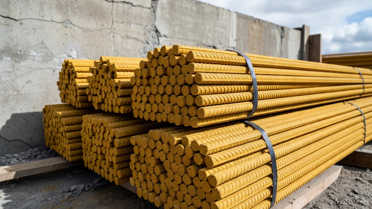
Manufacturing is primarily by pultrusion: continuous fiber rovings are pulled through a resin bath and then through a heated die where the thermosetting resin cures. Surface deformations — helical fiber wraps, sand coatings, or ribbed patterns — are applied during or after pultrusion to enhance mechanical bond with concrete. Pultrusion speed ranges from 0.5–2.0 m/min, with cross-sectional tolerances of ±0.3–0.5 mm.
Applications: Bridge decks, marine structures, parking garages, water treatment plants, tunnels, chemical plants, MRI-safe facilities, and airport pavements. GFRP is the standard choice for corrosion-resistant reinforcement where high strength at moderate cost is required.
Carbon Fiber Reinforced Polymer (CFRP)
CFRP uses carbon fibers — available in standard modulus (T300/T700 grade, ~230 GPa), high modulus (~350 GPa), and ultra-high modulus (~580 GPa) variants. Carbon fibers have the highest tensile strength of any FRP fiber type at the fiber level: 3,500–4,900 MPa. The fiber elastic modulus ranges from 230–580 GPa depending on grade.
At the composite rebar level, CFRP delivers tensile strength of 1,720–3,690 MPa (250–585 ksi) and elastic modulus of 120–580 GPa (15,900–84,000 ksi). Ultimate strain is 0.5–1.9%, lower than other FRP types due to the carbon fiber’s high stiffness and lower elongation capacity. Density is 1.5–1.6 g/cm³. Per ACI 440.6-08, CFRP bars must have an elastic modulus of at least 124 GPa (18,000 ksi).
CFRP is electrically conductive — a critical distinction from GFRP, AFRP, and BFRP. This conductivity means CFRP cannot be used where electromagnetic neutrality is required (airport navigation aid zones, MRI suites). However, CFRP has the best creep-rupture resistance: sustained stress limit of 0.55 × ultimate strength, compared to 0.20 for GFRP — making it the preferred material for prestressing tendons and sustained-load applications.
Applications: High-load structural reinforcement, seismic retrofitting, prestressing tendons, aerospace structures, high-rise buildings, and bridge strengthening. CFRP is the primary material for externally bonded strengthening systems due to its high modulus-to-thickness ratio.
Aramid Fiber Reinforced Polymer (AFRP)
AFRP uses aramid fibers — commercially known as Kevlar (DuPont) or Twaron (Teijin). These fibers exhibit excellent toughness and impact energy absorption, exceeding both glass and carbon. Fiber-level tensile strength is approximately 3,600 MPa, with elastic modulus varying from 70–125 GPa depending on grade. Aramid fibers have the lowest density among FRP fibers: 1.44 g/cm³.
At the composite level, AFRP tensile strength ranges from 1,720–2,540 MPa (250–368 ksi), elastic modulus from 41–125 GPa (6,000–18,000 ksi), and ultimate strain from 1.9–4.4% — the highest strain capacity of any FRP type. This high strain capacity provides the best energy absorption for impact and blast loading. Density is 1.3–1.5 g/cm³.
AFRP has two significant limitations: UV sensitivity — aramid fibers degrade rapidly under ultraviolet exposure, requiring protective coatings or encapsulation in all exposed applications. Poor compressive strength — aramid fibers have low compressive strength relative to their tensile capacity, limiting applications in compression-dominated members.
Applications: Blast-resistant structures, ballistic protection, bridge pier impact protection, earthquake-resistant structures, and chemically aggressive environments. AFRP is less common in civil infrastructure than GFRP or CFRP due to higher cost and UV sensitivity.
Basalt Fiber Reinforced Polymer (BFRP) — Emerging
BFRP is the newest FRP type, using continuous fibers produced from melted volcanic basalt rock. Basalt fiber production requires no chemical additives — the rock is melted at approximately 1,400°C and drawn into continuous filaments. This makes BFRP production more environmentally sustainable than glass fiber production, which requires silica, limestone, and other raw material inputs. Fiber-level tensile strength reaches approximately 4,840 MPa with an elastic modulus of 89 GPa.
At the composite rebar level, BFRP delivers tensile strength of 1,035–1,650 MPa (150–240 ksi), elastic modulus of 45–59 GPa (6,500–8,500 ksi), and ultimate strain of 1.6–3.0%. Density is 1.9–2.1 g/cm³.
BFRP’s key advantages over GFRP include: better alkali resistance — the basalt fiber chemistry provides inherently better resistance to the alkaline concrete pore solution (pH 12–13). Superior fire resistance — BFRP bars show only 10% strength reduction after 90 minutes at 300°C compared to 75% reduction for GFRP bars. Cost near E-glass levels — making BFRP economically competitive with GFRP while offering performance approaching CFRP in some criteria. BFRP is non-conductive and non-magnetic.
ICC-ES AC454 (October 2020) now covers BFRP bars alongside GFRP for internal concrete reinforcement. IS 18256:2023 (Indian standard) covers GFRP rebar, with BFRP increasingly recognized in national codes.
Applications: Bridge decks in aggressive environments, marine structures, airport pavements (including the Florida Keys Marathon International Airport BFRP mesh installation), railway electrification structures, and MRI facilities.
FRP Rebar Mechanical Properties
Tensile Strength and Stress-Strain Behavior
The defining mechanical characteristic of FRP reinforcement is its linear-elastic stress-strain behavior to failure: FRP does not yield or exhibit plastic deformation. This is the most significant difference from steel reinforcement.
Steel reinforcement: Elastic behavior up to the yield point (~420 MPa for Grade 60), followed by a plastic plateau to ultimate strain of 10–15%, providing ductility and warning before failure. FRP reinforcement: Linear-elastic Hookean behavior from zero stress to ultimate failure (rupture). Failure is sudden and brittle without plastic deformation.
Material
Tensile Strength (MPa)
Elastic Modulus (GPa)
Ultimate Strain (%)
Density (g/cm³)
Steel (Grade 60)
420–550 (yield)
200
10–15 (ductile)
7.85
GFRP
480–1,600
35–51
1.2–3.1
1.7–2.0
BFRP
1,035–1,650
45–59
1.6–3.0
1.9–2.1
AFRP
1,720–2,540
41–125
1.9–4.4
1.3–1.5
CFRP
1,720–3,690
120–580
0.5–1.9
1.5–1.6
All values are at the composite (rebar) level. Fiber volume fraction: 0.50–0.70. Based on ACI 440.1R and manufacturer data.
Bond Behavior with Concrete
FRP bars achieve bond with concrete through mechanical interlock provided by surface treatments applied during manufacturing:
Helical wraps — continuous fiber tows wound helically around the bar surface, creating a spiral deformation pattern
Sand coatings — bonded particulate surface providing friction-based bond
Ribbed/deformed patterns — molded or machined deformations similar to steel rebar ribs
Bond strength of FRP bars with concrete is comparable to deformed steel rebar under normal conditions. Bond is governed by: concrete compressive strength, bar surface characteristics, confinement conditions (concrete cover, stirrups), and bar diameter. Development length equations in ACI 440.1R account for FRP’s lower elastic modulus and lack of yielding, requiring longer development lengths than steel for equivalent bond capacity.
Thermal Expansion
Thermal compatibility between FRP reinforcement and concrete is critical for structural durability in temperature-fluctuating environments:
Material
CTE Longitudinal (×10⁻⁶/°C)
CTE Transverse (×10⁻⁶/°C)
Concrete
~10
~10
Steel
11.7
11.7
GFRP
6–10
21–23
CFRP
0 to –1
21–23
AFRP
–2 to –6
30–60
GFRP provides the best thermal compatibility with concrete, with longitudinal CTE matching concrete closely at 6–10 ×10⁻⁶/°C. CFRP has a near-zero or slightly negative longitudinal CTE, which can create thermal incompatibility — the CFRP bar does not expand with the surrounding concrete during temperature increase, potentially causing radial cracking or bond degradation. AFRP exhibits negative longitudinal CTE, creating significant expansion mismatch.
Shear Strength and Dowel Action
FRP bars have low transverse shear strength — typically 10–20% of their longitudinal tensile strength. This is because FRP’s strength is derived from the continuous fibers oriented longitudinally, with the resin matrix providing relatively weak transverse load transfer. The dowel action contribution of FRP reinforcement in concrete members is substantially reduced compared to steel reinforcement.
Per ACI 440.1R, FRP stirrups must be designed with significantly reduced strength values. Research by the Florida Department of Transportation found that BFRP rebars have demonstrated 116% higher transverse shear strength than GFRP bars, attributed to basalt fiber’s higher intrinsic shear resistance.
Creep Rupture and Fatigue
Creep rupture — time-dependent failure under sustained tensile stress at levels well below short-term ultimate strength — is a critical design consideration for FRP reinforcement:
FRP Type
Creep-Rupture Stress Limit (× f_fu)
Fatigue Stress Limit (× f_fu)
GFRP
0.20
0.20
BFRP
0.20
0.20 (per FDOT)
AFRP
0.30
0.30
CFRP
0.55
0.55
Per ACI 440.1R. f_fu = guaranteed ultimate tensile strength of the FRP bar.
CFRP’s superior creep-rupture resistance (0.55 × f_fu) gives it a significant advantage for prestressing tendons and sustained-load applications. GFRP and BFRP are limited to 0.20 × f_fu, meaning only 20% of the bar’s tensile capacity can be utilized under sustained loading. Service stress limits must be checked per ACI 440.1R Section 7.4.
FRP Rebar vs. Steel Rebar
Full Comparison
Property
GFRP Rebar
Steel Rebar (Grade 60)
Tensile Strength
1,000+ MPa (ultimate)
420–600 MPa (yield)
Elastic Modulus
40–60 GPa
200 GPa
Yield Behavior
None — linear-elastic to rupture
Ductile yielding at ~420 MPa
Ultimate Strain
1.2–3.1%
10–15%
Weight
~2,100 kg/m³ (75% lighter)
7,850 kg/m³
Corrosion Resistance
Completely immune
Susceptible to rust and corrosion
Service Life (aggressive)
100+ years
25–50 years (with maintenance)
Thermal Conductivity
~0.35 W/m·K (insulator)
~50 W/m·K (thermal bridge)
Electrical Conductivity
Non-conductive
Conductive
Magnetic
Non-magnetic
Magnetic
Shear Strength
Low (10–20% of tensile)
~60% of tensile
On-site Bending
Not possible — factory-bent only
Can be field-bent
Welding
Not possible
Can be welded
Initial Material Cost
10–30% higher
Lower
Lifecycle Cost
Significantly lower
Higher (maintenance, repairs)
Key Advantages
Corrosion immunity is the primary driver for FRP adoption. GFRP is completely immune to chlorides, de-icing salts, seawater, acidic environments, and alkaline concrete pore solution. Steel corrosion-driven concrete spalling is the leading cause of premature reinforced concrete failure worldwide. FRP eliminates this failure mechanism entirely.
Strength-to-weight ratio — FRP delivers approximately twice the tensile strength of steel at one-quarter the weight. This dramatically reduces transportation costs, eliminates the need for heavy lifting equipment on site, reduces worker handling fatigue, and enables lighter structural elements.
Electromagnetic neutrality — GFRP, BFRP, and AFRP are non-magnetic and non-conductive. This is essential for structures near airport navigation aids (Instrument Landing System, VOR, DME), MRI suites in medical facilities, sensitive electronics manufacturing, and high-voltage environments. CFRP is electrically conductive and does not share this advantage.
Service life — properly manufactured FRP reinforcement provides 100+ years of service life in aggressive environments where steel would require replacement within 25–50 years. This long-term durability fundamentally changes infrastructure lifecycle economics.
Key Limitations
No ductility — FRP does not yield or undergo plastic deformation. Failure is sudden and brittle. This fundamentally changes structural redundancy and energy dissipation behavior, requiring special consideration for seismic design. ACI CODE 440.11 currently limits GFRP-reinforced concrete to Seismic Design Category A or B (low seismic risk).
Lower elastic modulus — GFRP’s elastic modulus (40–60 GPa) is approximately one-fifth of steel’s 200 GPa. FRP-reinforced members exhibit greater deflections and wider crack widths for equivalent reinforcement ratios, requiring larger bar diameters or closer spacing to satisfy serviceability limits.
Cannot be field-bent — FRP bars must be bent at the factory during manufacturing. All bend configurations must be predetermined at the design stage. Field bending is not possible without damaging the fibers and resin matrix.
Low shear strength — FRP bars have poor transverse shear strength. They cannot be used as dowels in the same manner as steel. The dowel action contribution is substantially reduced in design calculations.
Fire sensitivity — FRP mechanical properties degrade above the resin’s glass transition temperature (T_g) , typically 65–150°C depending on resin formulation. In a fire event, FRP reinforcement is assumed to contribute zero structural capacity per ACI 440.1R and ACI 440.2R. The structural member must be capable of resisting all loads without FRP contribution during fire exposure.
Externally Bonded FRP (EBR) for Strengthening
Externally Bonded Reinforcement (EBR) using FRP composites is the leading technique for strengthening existing concrete structures. Compared to traditional methods (steel plate bonding, section enlargement, external post-tensioning), FRP systems offer negligible added dead load, ease of installation with minimal equipment, zero corrosion maintenance, and a thin profile that preserves structural aesthetics and clearances.
Application Methods
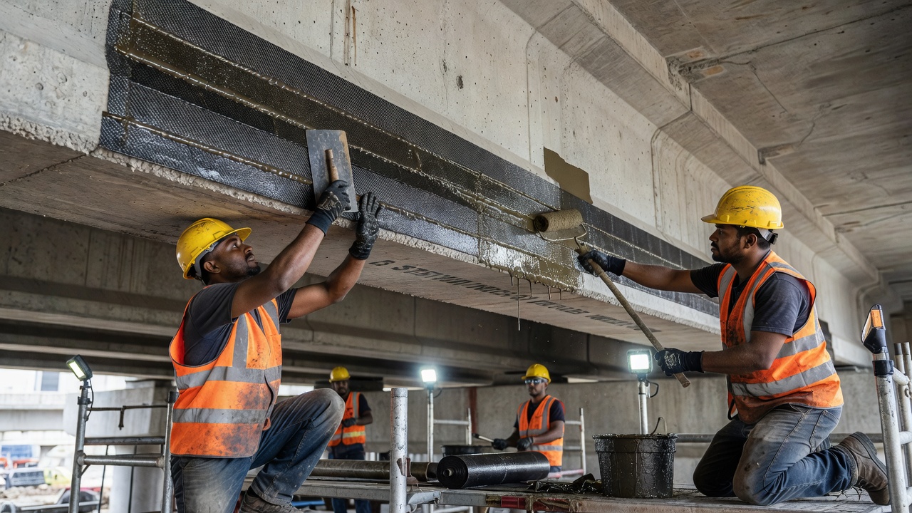
Wet Layup System: Dry unidirectional or multidirectional fiber sheets are impregnated with saturating resin on site and applied directly to the prepared concrete substrate. Multiple plies can be applied in sequence. This system conforms to irregular geometries and curved surfaces. Curing occurs at ambient temperature. Quality control depends significantly on installer skill — resin mixing ratios, fiber saturation, and air void elimination are critical.
Precured (Prefabricated) Strips/Laminates: Factory-manufactured FRP laminates (typically CFRP, 1–2 mm thick, 50–150 mm wide) are bonded to the concrete substrate using epoxy adhesive. Factory-controlled quality ensures consistent fiber volume fraction and void content. Limitations: less adaptable to complex geometries, limited to flat or gently curved surfaces.
Near-Surface Mounted (NSM) Method: Grooves are cut into the concrete cover (typically 3–5 mm wide, depth equal to bar diameter). FRP bars or strips are placed into grooves filled with epoxy or cementitious paste. NSM provides better bond performance than EBR, is less susceptible to debonding failures, and is better protected from fire, vandalism, and UV exposure. NSM is increasingly preferred for flexural strengthening of beams and slabs.
Design Philosophy per ACI 440.2R
Strain limitations are imposed to conservatively account for debonding failure modes, which often govern before FRP rupture. The maximum usable FRP strain for flexural strengthening is limited to κ_m × ε_fu (bond-dependent coefficient, typically 0.5–0.7), not to exceed 0.005.
Fire philosophy: FRP-strengthened members are assumed to lose all FRP contribution in fire. The structural member without FRP must resist all applicable loads during fire.
Strengthening limits: Maximum strength increase is typically limited to 40–60% of original capacity to prevent sudden failure scenarios.
Debonding Failure Modes
Four distinct debonding modes are identified per ACI 440.2R:
Plate-end debonding — initiates at the FRP termination point where shear and normal stress concentrations are highest
Mid-span debonding (intermediate crack-induced) — initiates at flexural cracks in the concrete member
Concrete cover separation — propagates along the plane of the existing steel tensile reinforcement
FRP delamination — failure within the FRP laminate itself (material interlaminar failure)
Surface must be sound, clean, free of laitance, dust, oil, and curing compounds
Surface preparation: grinding, sandblasting, or water-jetting
Concrete temperature at installation: typically above 10°C (50°F)
FRP Design Standards
ACI 440.1R-15 — Guide for the Design and Construction of Structural Concrete Reinforced with FRP Bars. This is the primary design guide for non-prestressed FRP reinforcement. Design follows limit-states philosophy using strength reduction factors derived from reliability analysis. Flexural design is based on strain compatibility and equilibrium. Three failure modes are considered: compression-controlled (concrete crushes before FRP rupture — preferred for ductility), tension-controlled (FRP rupture before concrete crushing), and balanced (simultaneous failure).
ACI CODE 440.11-22 — Building Code Requirements for Structural Concrete Reinforced with Glass Fiber-Reinforced Polymer (GFRP) Bars. This is the first mandatory code for GFRP-reinforced concrete, adopted by reference in the International Building Code (IBC). Permits GFRP reinforcement for all structural elements in Seismic Design Category A or B, using normal-weight concrete. References ACI 318 as the base code, with modifications for GFRP material behavior.
ACI 440.2R-17 — Guide for the Design and Construction of Externally Bonded FRP Systems for Strengthening Concrete Structures. Covers flexural strengthening, shear strengthening, column confinement, axial strengthening, and seismic retrofit using externally bonded FRP systems.
AASHTO LRFD Bridge Design Guide Specifications for GFRP-Reinforced Concrete (2nd Edition, 2018) — Adopted by FDOT and other state DOTs as the design standard for GFRP-reinforced concrete bridges. Permitted applications include approach slabs, bridge decks, flat slab superstructures, pile bent caps, retaining walls, noise walls, and drainage structures.
ICC-ES AC454 (October 2020) — Acceptance Criteria for Fiber-Reinforced Polymer Bars for Internal Reinforcement of Concrete Members. Covers GFRP and BFRP bars (cut lengths, bent shapes, closed stirrups, and ties). Requires physical and mechanical property evaluation, accelerated environmental exposure testing (alkaline, moisture, freeze-thaw), and fire performance testing. First evaluation reports issued March 2021 for Tuf-N-Lite (ESR-4664) and Neuvokas (ESR-4526). FRP bars are limited to structures in Seismic Design Category A or B with normal-weight concrete.
ICC-ES AC521 (December 2020) — Acceptance Criteria for Fiber-Reinforced Polymer Meshes Used as Secondary Reinforcement. Covers FRP meshes for temperature and shrinkage reinforcement.
International Standards:
Standard
Jurisdiction
Scope
CSA S806-12
Canada
FRP-reinforced concrete design
CSA S807
Canada
FRP material specification
CAN/CSA-S6-06
Canada
Highway bridge design (FRP provisions)
JSCE (1997)
Japan
FRP concrete design guidelines
fib Bulletin 40
Europe
FRP in concrete structures
IS 18256:2023
India
GFRP rebar specification
ASTM D7957
USA
FRP bar specification
FRP in Bridges and Airport Structures
Bridge Applications
The FHWA Innovation Bridge Research and Construction (IBRC/IBRD) Program has funded numerous FRP bridge demonstration projects. Bridge deck reinforcement is the most mature FRP bridge application, with GFRP rebar used in decks across multiple states.
FDOT-permitted FRP bridge applications per the FRP Guidelines (January 2019) include: approach slabs, bridge decks and overlays, cast-in-place flat slab superstructures, pile bent caps, pier columns and caps (not in direct contact with water), retaining walls, noise walls, pedestrian/bicycle railings, drainage structures, and expansion joint dowel bars.
Airport Structure Applications
Four key drivers make FRP reinforcement particularly valuable for airport infrastructure:
Electromagnetic neutrality — GFRP, BFRP, and AFRP are non-magnetic and non-conductive, eliminating interference with the Instrument Landing System (ILS), VHF Omnidirectional Range (VOR), Distance Measuring Equipment (DME), Precision Approach Path Indicator (PAPI), and ground radar. ICAO Annex 10 defines critical and sensitive areas around navigation aids where ferromagnetic materials are restricted, and navigation equipment manufacturers may mandate non-ferromagnetic reinforcement in foundations and pavements near these facilities.
De-icing chemical resistance — GFRP is fully resistant to ethylene glycol, propylene glycol, potassium acetate, sodium acetate, and urea-based de-icing compounds. These chemicals rapidly attack steel reinforcement through chloride-induced corrosion.
Aviation fuel and hydraulic fluid resistance — GFRP is fully resistant to Jet A-1, Jet A, Jet B, ATF (aviation turbine fuel), and hydraulic fluids (Skydrol, MIL-PRF-83282). Spills in apron areas cause no degradation.
Long service life — 100+ years in aggressive apron and runway environments versus 25–50 years for steel reinforcement in the same conditions.
Specific airport applications:
Runway pavements — Continuously Reinforced Concrete Pavement (CRCP) with GFRP eliminates corrosion risk from de-icing chemicals and eliminates the need for joints that require maintenance. Particularly valuable at coastal airports where chloride ingress from marine atmosphere accelerates steel corrosion.
Taxiway pavements — slow-speed, heavy loads from wide-body aircraft. GFRP eliminates corrosion in fuel and hydraulic fluid spill zones. The non-magnetic property benefits taxiways near guidance lighting systems.
Apron areas — the most chemically aggressive pavement environment. Fuel spills, hydraulic fluid leaks, and de-icing chemical runoff create conditions that rapidly degrade steel reinforcement. GFRP eliminates corrosion-driven deterioration in these areas entirely.
Terminal buildings — ground floor slabs, basements, and drainage structures benefit from corrosion immunity in coastal environments.
ATC and navigation aid structures — ATC tower foundations, VOR/DVOR shelters, ILS equipment foundations, radar towers, and PAPI light foundations. GFRP may be mandated by navigation equipment manufacturers to avoid electromagnetic interference with sensitive electronic systems.
Florida Keys Marathon International Airport — BFRP mesh was installed as secondary reinforcement in a hangar floor slab (3.6 mm diameter wire, 100 × 100 mm grid), demonstrating the viability of basalt FRP in airport infrastructure.
Inspection of FRP-Reinforced and FRP-Strengthened Structures
Inspection of FRP-reinforced and FRP-strengthened concrete structures requires different defect recognition than conventional steel-reinforced concrete. FRP-strengthened structures can experience bond defects and delaminations that are invisible to the naked eye but structurally critical.
Visual Inspection
The primary screening method — fast, inexpensive, and capable of covering large areas. Detects: surface cracks in the FRP laminate or surrounding concrete, discoloration indicating UV degradation or chemical attack, exposed fibers indicating abrasion or impact damage, blistering indicating entrapped moisture or air, edge debonding at FRP termination points, and apparent substrate deterioration.
Limitation: Cannot detect subsurface bond defects. Debonded areas beneath the FRP laminate are often invisible until they propagate to an exposed edge.
Tap Testing (Sounding)
A simple and effective NDT method for FRP-strengthened concrete. The inspector taps the FRP surface with a light hammer, coin, or specialized tapping tool and listens to the acoustic response.
Sound interpretation: A solid, sharp, ringing sound indicates good bond and intact laminate. A hollow, dull, or drum-like sound indicates delamination or a bond defect beneath the FRP. This technique is recommended by ACI 440.2R for initial inspection and periodic condition assessment.
Limitations: Subjective — relies on inspector experience and hearing acuity. Difficult in noisy airport or construction environments. Limited depth penetration. Cannot quantify defect size or thickness. Provides no permanent record unless coordinates are mapped manually.
Ultrasonic Testing
The most reliable method for damage detection in FRP bars per research studies. High-frequency sound waves (typically 1–10 MHz) are introduced into the material. Techniques include:
Pulse-echo — single transducer sends and receives reflected sound waves. Time-of-flight indicates defect depth.
Through-transmission — separate transmitter and receiver on opposite sides. Signal loss indicates defects.
Phased array — multiple transducer elements electronically steered for detailed cross-sectional imaging.
Ultrasonic testing detects: internal delaminations, fiber breakage, voids in the resin matrix, bond defects between FRP and concrete substrate, and thickness variations in the FRP laminate.
Advantages: Quantitative data output, subsurface defect detection, depth information, permanent record capability. Limitations: Requires couplant (gel or water), slower inspection speed than visual or tap testing, requires skilled operator, complex geometries challenging.
Infrared Thermography
The most applicable method for detecting bond defects underneath FRP systems per research findings. Functions by detecting differences in surface temperature caused by subsurface defects — debonded areas have different thermal conductivity than well-bonded areas.
Under passive heating (solar radiation) or active thermal excitation (heat lamps), debonded regions heat or cool at different rates than sound regions, creating a thermal contrast visible in infrared imagery.
Advantages: Non-contact inspection, rapid scanning of large areas, real-time imaging, quantitative temperature data, permanent image record. Limitations: Environmental conditions significantly affect results (sunlight, wind, ambient temperature, precipitation), limited depth penetration (typically 10–30 mm for CFRP on concrete), requires sufficient thermal contrast (minimum 0.5–1°C temperature differential).
Other NDT Methods
Method
Application
Advantages
Limitations
Ground Penetrating Radar
Locating FRP bars in concrete, void detection
Rapid, non-contact scanning
Limited resolution for thin FRP laminates
Acoustic Emission
Monitoring damage progression under load
Real-time, covers large area
Requires loading; background noise interference
Fiber Bragg Grating Sensors
Embedded or surface-mounted strain monitoring
Continuous, quantitative data
Point sensing only; cost per sensor
Laser Shearography
Detecting subsurface delaminations
Full-field, high sensitivity
Equipment cost; vibration sensitive
Radiography (X-ray)
Internal defect visualization
Direct visual of internal condition
Radiation safety; access both sides; cost
Inspection Frequency per ACI 440.2R
Initial (post-installation): 100% visual inspection plus tap testing of the entire FRP system. All defects must be documented and evaluated.
Periodic: Annual or biennial visual inspection. Tap testing if the FRP is accessible. Condition assessment per environmental exposure classification.
After events: Following seismic events, impact loading, fire exposure, or unusual service load conditions — full NDT evaluation of potentially affected areas.
Repair assessment: Full NDT evaluation of any damaged or repaired areas.
Bond Defect Acceptance Criteria per ACI 440.2R
Small isolated defects covering less than 5% of the bond area: Acceptable with monitoring during subsequent inspections.
Large defects or defects showing growth between inspections: Must be repaired per manufacturer’s procedures.
Edge delaminations at FRP termination points: Must be repaired regardless of size, due to their tendency to propagate under service loads.
Durability of FRP
UV Degradation
Ultraviolet radiation embrittles the polymer resin matrix and can cause loss of tensile strength in glass fibers. AFRP is particularly UV-sensitive — exposure to direct sunlight can cause significant strength reduction within months without protection.
Mitigations: UV inhibitors added to the resin formulation during manufacturing. Surface coatings (veils, gel coats) that block UV transmission. Protective paint systems applied after installation. Cementitious or epoxy cover for embedded applications.
Per FDOT FRP Guidelines: “Ultraviolet light embrittles the matrix and may cause loss of tensile strength in glass fibers. Ultraviolet light is best dealt with by using surface coatings (veils) with UV inhibitors.”
FRP used below grade or enclosed within buildings has negligible UV exposure concern.
Alkaline Environment
Concrete pore solution has a pH of 12–13 — highly alkaline. E-glass fibers are susceptible to alkaline attack, experiencing strength degradation over time in direct contact with moist concrete.
Mitigations: AR-glass (alkali-resistant glass fibers) provide improved resistance. Vinyl ester and epoxy resins provide better chemical barriers than polyester resins. BFRP offers inherently better alkali resistance than E-glass GFRP due to basalt’s mineral composition. Proper concrete cover provides physical protection and limits moisture access.
Research from the Euroconcrete Project found that GFRP resists alkaline environments well, with no significant degradation during 12-month exposure tests. However, long-term (50+ years) durability data remains limited for all FRP types.
Fire Resistance
FRP mechanical properties degrade significantly above the resin’s glass transition temperature (T_g) , typically 65–150°C depending on resin chemistry. At fire temperatures exceeding 500°C, the resin combusts or softens completely, and the FRP loses all structural capacity.
Design assumption per ACI 440.1R and ACI 440.2R: The structural member without FRP must possess sufficient strength to resist all applicable loads during a fire. Externally bonded FRP is assumed to contribute zero structural capacity during fire exposure.
Mitigations: Fire protection coatings (intumescent paints that expand when heated, cementitious sprays). Phenolic resin systems with higher intrinsic fire resistance. Sufficient concrete cover for internal FRP bars (typically 50–75 mm for fire rating). Additional structural capacity in the member independent of FRP contribution.
BFRP advantage: BFRP bars show only 10% strength reduction after 90 minutes at 300°C versus 75% reduction for GFRP bars, making basalt FRP significantly more fire-resistant.
Freeze-Thaw
FRP materials generally show good freeze-thaw resistance due to the polymer matrix’s flexibility. Repeated freeze-thaw cycles can cause microcracking in the resin matrix, degradation of the fiber-resin interface, and moisture ingress leading to further deterioration.
Standard freeze-thaw testing per ASTM C666 shows minimal strength reduction (less than 10%) for properly manufactured FRP bars. Combined effects — freeze-thaw cycling plus sustained load plus alkaline exposure — are more critical and less understood in long-term research.
Creep Rupture
Creep rupture is time-dependent failure under sustained tensile stress at levels well below short-term ultimate strength. The creep-rupture stress limits per ACI 440.1R are:
GFRP: 0.20 × f_fu (most susceptible)
BFRP: 0.20 × f_fu (per FDOT acceptance)
AFRP: 0.30 × f_fu (moderate)
CFRP: 0.55 × f_fu (most resistant)
These limits mean that GFRP can utilize only 20% of its ultimate tensile strength under sustained loading conditions. CFRP’s higher limit makes it the preferred material for prestressing tendons and other sustained-load applications.
Environmental Reduction Factors (C_E) per ACI 440.1R
Exposure Condition
CFRP
GFRP / AFRP
Interior (protected)
1.0
0.80
Exterior (bridges, piers)
0.90
0.70
Aggressive (chemical, marine)
0.85
0.60
Design tensile strength = C_E × f_fu*, where f*_fu is the guaranteed tensile strength.
Future of FRP in Infrastructure
BFRP is emerging as a potential standard for corrosion-resistant reinforcement. Its tensile strength (1,035–1,650 MPa) lies between GFRP and CFRP. Superior alkali resistance compared to E-glass GFRP, better fire resistance (only 10% strength loss at 300°C vs 75% for GFRP), cost near E-glass levels, and environmentally friendlier production (basalt is natural volcanic rock requiring no chemical additives) position BFRP for widespread adoption.
Hybrid FRP bars combine two or more fiber types — for example, carbon-glass hybrids using carbon fibers for high stiffness and glass for cost reduction and pseudo-ductility (progressive failure providing warning before collapse). Steel-FRP hybrid bars (steel core for ductility, FRP outer layer for corrosion resistance) are in active research with limited commercial availability.
Smart FRP with embedded sensors — Fiber Bragg Grating (FBG) sensors embedded in FRP bars enable real-time structural health monitoring. Smart BFRP bars function simultaneously as reinforcement and strain sensors, measuring strain, temperature, damage progression, and crack width. Research on IoT-enabled infrastructure monitoring and integration with digital twin models is advancing.
Sustainable FRP developments include bio-based resins from renewable sources (plant oils, lignin), recycled carbon fiber from aerospace waste, thermoplastic FRP matrices that can be remelted and reformed, and improved end-of-life recycling through pyrolysis. FRP’s 100+ year service life and elimination of corrosion maintenance offset its recycling limitations.
Code development trajectory: ACI CODE 440.11 (2022) is the first mandatory code for GFRP-reinforced concrete, currently limited to Seismic Design Category A and B. Anticipated expansion to cover SDC C and above in future editions. BFRP inclusion in code provisions expected as the research database grows. AASHTO integration of FRP provisions into the main LRFD specifications from current guide specification format. International harmonization of FRP design standards is progressing through organizations including fib, RILEM, and ISO.
Emerging applications: 3D-printed FRP reinforcement for custom geometries, FRP combined with Engineered Cementitious Composites (ECC) for enhanced ductility, geopolymer resin FRP for improved fire and chemical resistance, prefabricated FRP-reinforced concrete modules for accelerated construction, and predictive long-term durability models validated against field data from early-generation installations now reaching 30–40 years of service.
The fundamental shift toward FRP reinforcement represents a transformation in concrete infrastructure durability. The ability to eliminate corrosion as a failure mechanism — the primary cause of premature concrete deterioration worldwide — enables 100+ year service life for critical infrastructure. At airports, the additional benefit of electromagnetic neutrality makes FRP not just an alternative to steel but the preferred reinforcement for navigation-critical zones. The maturation of design codes (ACI 440.11-22, ICC-ES AC454, AASHTO FRP Guide Specifications) provides the regulatory framework for widespread adoption, while emerging BFRP technology and hybrid systems promise continued innovation in performance and cost-effectiveness.
Frequently Asked Questions
Four fiber types are used in FRP reinforcement for concrete: **Glass Fiber Reinforced Polymer (GFRP)** — the most common and cost-effective, using E-glass or AR-glass fibers, tensile strength 480–1,600 MPa, elastic modulus 35–51 GPa. **Carbon Fiber Reinforced Polymer (CFRP)** — highest strength and stiffness, tensile strength 1,720–3,690 MPa, modulus up to 580 GPa, but electrically conductive and most expensive. **Aramid Fiber Reinforced Polymer (AFRP)** — highest toughness and impact resistance (Kevlar type), tensile strength 1,720–2,540 MPa, but UV-sensitive and poor in compression. **Basalt Fiber Reinforced Polymer (BFRP)** — emerging type from volcanic basalt rock, tensile strength 1,035–1,650 MPa, better alkali resistance than GFRP, better fire resistance, cost near GFRP level.
FRP rebar offers several key advantages over steel: **corrosion immunity** — completely resistant to chlorides, de-icing salts, seawater, chemicals. **Higher tensile strength** — GFRP at 1,000+ MPa vs Grade 60 steel at 420 MPa yield. **75% lighter** — density 2,100 kg/m³ vs 7,850 kg/m³. **Non-magnetic and non-conductive** — critical near airport navigation aids (ILS, VOR). **100+ year service life** in aggressive environments. Key limitations: **no ductility** — FRP is linear-elastic to brittle failure. **Lower elastic modulus** — GFRP at 40–60 GPa vs steel at 200 GPa, causing greater deflections. **Cannot be field-bent** — all bends must be factory-made. **Poor shear strength** — only 10–20% of longitudinal strength. **Fire concerns** — resin softens above 65–150°C glass transition temperature.
Multiple standards govern FRP reinforcement design: **ACI 440.1R-15** — Guide for Design and Construction of Structural Concrete Reinforced with FRP Bars. **ACI CODE 440.11-22** — Building code requirements for GFRP-reinforced concrete (adopted in IBC). **ACI 440.2R-17** — Guide for Externally Bonded FRP Strengthening Systems. **AASHTO LRFD Bridge Design Guide Specifications for GFRP-Reinforced Concrete** (2nd Edition, 2018) — for bridge applications. **ICC-ES AC454** (October 2020) — Acceptance criteria for FRP bars as internal reinforcement. **ICC-ES AC521** — FRP meshes for secondary reinforcement. International standards include **CSA S806** (Canada), **fib Bulletin 40** (Europe), **JSCE** (Japan), and **IS 18256:2023** (India).
FRP reinforcement is required or strongly recommended at airports where: **Electromagnetic neutrality** is needed — GFRP/BFRP/AFRP are non-magnetic and non-conductive, eliminating interference with ILS, VOR, DME, PAPI, and ground radar systems. ICAO Annex 10 defines critical/sensitive areas around navigation aids where ferromagnetic materials are restricted. **De-icing chemical resistance** — GFRP is fully resistant to glycol, acetate, and urea de-icing compounds that rapidly corrode steel. **Aviation fuel resistance** — fully resistant to Jet A-1, ATF, and hydraulic fluids. **Long service life** — 100+ years in aggressive apron environments vs 25–50 years for steel. Applications include runway CRCP, taxiway pavements, apron slabs, terminal building slabs, and ATC tower foundations.
Inspection of FRP-strengthened and FRP-reinforced structures requires specific NDT methods: **Visual inspection** — primary screening for surface cracks, discoloration, exposed fibers, blistering, and edge debonding. **Tap testing** (sounding) — simple hammer tap test detects hollow-sounding areas indicating delamination or bond defects; recommended by ACI 440.2R for initial inspection. **Ultrasonic testing** — most reliable for FRP bar damage detection; pulse-echo and phased array methods detect internal delaminations and fiber breakage. **Infrared thermography** — most applicable method for bond defect detection under FRP systems; detects thermal conductivity differences at debonded areas. **Ground penetrating radar** — locates FRP bars in concrete and detects voids. **Acoustic emission** — monitors damage progression under load. Per ACI 440.2R, bond defects covering less than 5% of bond area are acceptable with monitoring; defects larger than 5% must be repaired.
Need expert FRP inspection?
Contact TarmacView for professional inspection services of FRP-reinforced and FRP-strengthened concrete structures — bridge decks, airport pavements, and marine infrastructure.
Fiber-Reinforced Concrete (FRC) contains distributed short fibers (steel, synthetic macro, glass, carbon, natural) to control cracking, improve toughness, and r...
Rebar is steel reinforcing bar embedded in concrete to carry tensile loads that concrete alone cannot resist. In infrastructure inspection, rebar condition is p...
Epoxy-coated rebar (ECR) is steel reinforcing bar coated with fusion-bonded epoxy powder applied via electrostatic spray in a factory environment. It provides a...
21 min read
Construction
Reinforcement
+3
Cookie Consent We use cookies to enhance your browsing experience and analyze our traffic. See our privacy policy.