Drone Flight Planning for Infrastructure Inspection
Drone flight planning for infrastructure inspection involves designing automated flight paths (waypoint missions) with appropriate altitude, speed, overlap, gimbal angle, and camera settings to capture consistent, high-quality inspection imagery. Covers mission types, software, parameter optimization, terrain following, airspace regulations, and pre-flight procedures.
Drone Flight Planning for Infrastructure Inspection
Purpose of Drone Flight Planning and Software
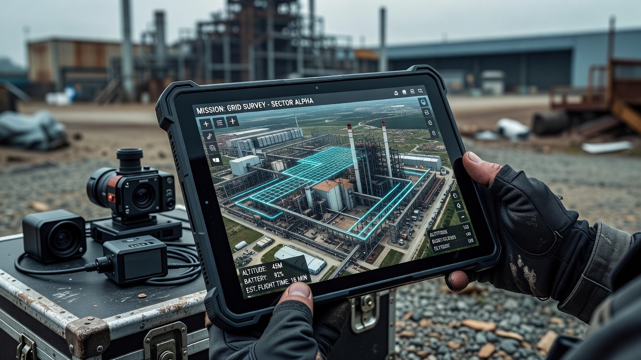
Drone flight planning for infrastructure inspection is the structured process of converting a deliverable specification into a repeatable flight that captures the right data on the first attempt. The core objectives are ensuring data quality through uniform Ground Sampling Distance (GSD), sufficient overlap, and proper camera settings for photogrammetric reconstruction; safety by avoiding obstacles, maintaining visual line of sight (VLOS), respecting airspace boundaries, and programming failsafes; repeatability through standardized missions that produce consistent data across multiple flights for periodic inspections; and efficiency by minimizing flight time and battery consumption while achieving complete coverage.
As noted by SPH Engineering, a successful mission is 90 percent planning and 10 percent execution. The global drone flight-planning software market was valued at approximately $259 million in 2025 and is projected to reach $449 million by 2032, representing an 8.3 percent compound annual growth rate (CAGR), driven by increasing adoption of UAVs for infrastructure inspection across aviation, energy, construction, and transportation sectors.
Flight Planning Software
Pix4Dcapture is a free mobile application for iOS and Android that supports grid, double grid, corridor, circular (orbital), and free-flight mission types. It processes data through Pix4Dmatic, Pix4Dmapper, or Pix4Dcloud, with typical overlap defaults of 75-85 percent frontal and 60-70 percent side overlap. It supports terrain awareness via pre-loaded digital elevation models (DEM). The software is best suited for photogrammetry-centric workflows end-to-end, from mission planning to point cloud generation and orthomosaic creation.
DJI Pilot 2 is the official flight application for DJI Enterprise drones including the Matrice 300/350 RTK, Matrice 3D/3TD, Mavic 3 Enterprise series, and Matrice 30/M30T. It supports terrain follow with custom DTM/GeoTIFF import and requires RTK positioning for terrain follow on certain firmware versions, with a minimum altitude of 25 meters AGL above the DSM. The March 2023 DJI Enterprise firmware update introduced real-time terrain follow supporting altitudes from 30 to 200 meters AGL. DJI Pilot 2 accepts KMZ mission files exported from third-party planners and displays above-sea-level altitude calculated using the EGM96 geoid model. It is best suited for the DJI Enterprise ecosystem and RTK-enabled precision flights.
DroneDeploy is a cloud-based platform offering a full workflow from flight planning through processing and analysis. It uses DEM data to adjust altitude for consistent AGL with recommended overlap of 70 percent front and 60 percent side as defaults for mapping. It supports DJI, Autel, Skydio, and other platforms, and features LAANC integration for airspace authorization. DroneDeploy is best suited for end-to-end operations teams in construction and agriculture.
UgCS (Universal Ground Control Software) by SPH Engineering is a desktop flight planning platform supporting DJI, ArduPilot, and PX4 autopilots. Its photogrammetry tool calculates flight lines, camera trigger intervals, and terrain-following waypoints based on camera specifications and desired GSD. UgCS includes a dedicated photogrammetry corridor tool for linear features, LiDAR flight planning with calibration patterns, 3D mission visualization against imported KML/KMZ obstacles, and a built-in flight simulator for pre-flight verification. Available in PRO, EXPERT, and ENTERPRISE licenses, UgCS is trusted by over 5,000 drone teams worldwide and is best for complex professional missions involving LiDAR, magnetometry, and research-grade work.
Mission Planner is the open-source ground control station for ArduPilot autopilots, supporting waypoint, survey (grid), corridor, and auto missions with full MAVLink telemetry monitoring, geofence configuration, and RTL/failsafe/terrain-following setup. It is best suited for ArduPilot and PX4 open-source platforms and custom UAV builds.
Litchi is a mobile app for DJI consumer drones offering waypoint missions with full control over altitude, speed, heading, and gimbal pitch, orbit POI mode, focus mode, CSV export/import, and cloud-based mission sharing via Litchi Hub. It is best suited for cinematography and semi-automated inspections on DJI consumer platforms.
Other notable platforms include Dronelink (cross-platform mission planner for DJI and Autel), Skydio Autonomy (3D scan, orbital, and corridor missions with active obstacle avoidance), Auterion Mission Control (enterprise fleet management), DroneBlocks (visual programming for automated bridge inspection flights), and Propeller Aero (cloud processing with terrain follow mission planning).
Mission Types
2D Grid Missions
2D grid missions are the foundation of aerial mapping and inspection. The drone flies parallel flight lines across a defined polygon area with the camera pointed straight down at a nadir angle (gimbal pitch of -90 degrees). These missions produce orthomosaic images, which are geometrically corrected aerial photographs stitched into a single seamless map. They are used for land surveying, construction site monitoring, stockpile measurement, and bridge deck inspection.
Double grid or crosshatch missions fly perpendicular passes (north-south then east-west), significantly improving 3D reconstruction by capturing oblique angles on each pass. This technique is essential when the deliverable requires a full 3D model rather than a simple orthomosaic. Typical parameters for double grid missions are 80 percent front overlap on both passes and 70 percent side overlap.
Irregular boundaries are handled by most planners through polygon drawing directly on the map interface, allowing the operator to define precise area boundaries and exclude no-fly zones or obstacles within the larger site.
Corridor / Linear Missions
Corridor missions follow a polyline centerline with the drone flying parallel passes of defined corridor width, typically 10 to 500 meters depending on the asset and required resolution. These missions are used for pipeline inspection, power line inspection, road and railway surveys, river mapping, and runway inspections. The corridor mission type is essential for linear infrastructure where a standard grid would waste significant flight time covering large areas of non-relevant terrain.
UgCS Photogrammetry Corridor tool and DroneDeploy corridor mode are designed specifically for this mission type. For wide corridors, multiple parallel passes may be required depending on the desired GSD and camera sensor specifications.
Orbital / POI Missions
Orbital or Point of Interest (POI) missions fly the drone in a circle around a defined center point. They are used for tower inspection (cell towers, wind turbines, chimneys), bridge piers, and building features that require 360-degree inspection coverage. Key parameters include orbit radius (distance from center point), number of waypoints (higher numbers produce smoother circular paths), direction (clockwise or counter-clockwise), heading mode (always face center, follow path tangent, or fixed heading), and gimbal pitch (typically -45 degrees for oblique views of the POI).
Helix mode is a variant that spirals the drone from a start altitude to an end altitude, used for full-height tower and wind turbine inspection from base to nacelle. Parameters include start altitude, end altitude, and vertical step distance between each loop.
Facade Mapping Missions
Facade mapping missions fly the drone parallel to a building face in a vertical zigzag or lawnmower pattern for building exterior inspection and high-rise facade assessment. The operator draws a polyline along the base of the building, and the drone scans upward in vertical strips. The gimbal angle is set to approximately 0 degrees (horizontal) aimed directly at the building surface.
For tall structures, multiple orbital passes are conducted at different height layers. Key parameters include distance to object (5-20 meters), vertical spacing between passes (5-15 meters for 60-70 percent vertical overlap), and flight speed (1-3 meters per second). Videogrammetry — extracting frames from 4K video captured at 30 fps minimum — produces textured 3D meshes for measurable models. Cost studies show drone-based facade inspection typically costs 60 to 80 percent less than scaffold-based alternatives for mid-rise buildings.
3D Waypoint Missions
3D waypoint missions provide the highest level of control for complex inspections where automated grid or corridor patterns are insufficient. Each waypoint independently defines latitude, longitude, altitude, heading, gimbal pitch, and camera action. Missions can include curved path interpolation for smooth turns between waypoints. Export and import is supported via KML, CSV, or proprietary waypoint file formats in Litchi, UgCS, Mission Planner (.waypoints), and DJI Pilot 2 (KMZ).
Panorama Missions
The drone hovers at a single location and rotates to capture a 360-degree spherical panorama. Parameters include shots per row (e.g., 8 shots at 45-degree steps) and pitch angles. These missions are used for overview documentation and virtual walkthroughs.
Parameter Settings
Ground Sampling Distance (GSD)
GSD is the distance between two consecutive pixel centers measured on the ground. It is the fundamental resolution parameter for all photogrammetric missions. The standard formula per Pix4D is:
GSD = (H × SW) / (F × ImW)
Where H is flight height above terrain in meters, SW is sensor width in millimeters, F is focal length in millimeters, and ImW is image width in pixels. The equivalent simplified formula is:
GSD = (Flight Height × Pixel Size) / Focal Length
Practical GSD standards for infrastructure inspection:
Application
GSD Requirement
Crack detection on facades
0.5-1 cm/pixel
Facade defect-level detail
2 cm/pixel
Bridge deck condition survey
3 cm/pixel
Cut/fill volume calculations
5 cm/pixel
Stockpile estimates
7-10 cm/pixel
An important consideration is that even at constant flight altitude, terrain elevation differences and camera angle changes cause GSD variation across the project area. Pix4D computes an average GSD for the final orthomosaic.
Overlap — Frontlap and Sidelap
Image overlap is the most critical parameter for successful photogrammetric reconstruction. The two components are frontal overlap (frontlap), the overlap between consecutive images along the flight direction, and side overlap (sidelap), the overlap between adjacent flight lines.
Requirement
Frontal Overlap (Frontlap)
Side Overlap (Sidelap)
Minimum for 2D orthomosaic
75%
60%
Recommended for accurate 3D
80-85%
65-75%
DroneDeploy defaults
70%
60%
Pix4D recommended
75-85%
60-70%
UgCS recommended
75-85%
60-70%
Double grid for 3D
80% (both passes)
70% (both passes)
A 66 percent overlap is the minimum threshold for successful 3D reconstruction, as established by academic research on bridge deck photogrammetry. A 77 percent overlap achieves the highest coverage in bridge deck studies. Increasing overlap beyond 85 percent yields diminishing returns in geometric accuracy while significantly increasing flight time and processing load. Multiple flight paths at different angles improve local geometric accuracy more than simply increasing the overlap percentage.
Altitude
For mapping missions, typical altitude is 50-120 meters AGL for most survey work. Lower altitude provides better GSD but covers less area per flight, requiring more batteries and longer total mission time. Facade inspection altitude depends on building height and requires multiple passes at different levels. Under FAA Part 107, the maximum altitude is 400 feet (122 meters) AGL in uncontrolled airspace, with an exception allowing flights above 400 feet if the drone remains within 400 feet horizontally of a structure. DJI Pilot 2 terrain follow supports a minimum of 25 meters AGL with RTK and 30 to 200 meters in real-time terrain follow mode.
Flight Speed
Mapping and photogrammetry missions typically fly at 3-8 meters per second (10-28 km/h). Slower speeds allow faster shutter speeds, reducing motion blur, and the speed must be coordinated with the capture interval to maintain target overlap. LiDAR surveys operate at 3-10 meters per second depending on sensor specifications. Facade inspection uses 1-3 meters per second for detailed vertical passes. FAA Part 107 sets a maximum speed of 100 mph (44.7 m/s).
Gimbal Angle
The gimbal angle determines the camera orientation relative to the drone. A nadir angle of -90 degrees is standard for 2D orthomosaic mapping with the camera pointed directly downward. Oblique angles of -70 to -45 degrees are used for 3D model reconstruction to capture building sides and vertical features. A horizontal angle of 0 degrees is used for facade inspection aimed at the building surface. A -45 degree oblique is common for orbital and POI missions to capture both vertical and horizontal detail.
Camera Settings
Shutter speed should be set to a minimum of 1/500 second for mapping at speed, with 1/1000 second or faster recommended to reduce motion blur. ISO should be set to 100-400 for reduced noise, with auto-ISO limited to a maximum of 800. Aperture is typically fixed or auto on drone cameras (f/2.8 to f/11). White balance must be set manually (e.g., Sunny at 5500K) for consistent color across all images in a dataset. Capture interval is auto-calculated by the mission planner based on speed, altitude, and target overlap. ND filters should be used in bright conditions to maintain proper shutter speed without overexposure. Typical capture intervals are 1-3 seconds for mapping at 5-8 m/s.
Terrain Following
Without terrain following, a drone flying at constant AMSL (above mean sea level) altitude over hilly terrain will have varying AGL distance, causing non-uniform GSD (higher resolution on hilltops, lower in valleys), coverage gaps or insufficient overlap in low areas, and potential collision risk on rising terrain.
DJI Pilot 2 terrain follow accepts GeoTIFF DTM (Digital Terrain Model) or DSM (Digital Surface Model) files for terrain data. Critically, DJI Pilot 2 requires heights relative to the WGS84 ellipsoid, not orthometric (sea-level) heights. DTM represents bare ground and is used for forestry and bare-earth surveys, while DSM includes buildings and vegetation for infrastructure inspection. DJI drones display ASL using the EGM96 geoid model internally, but the terrain file must use ellipsoidal heights with the geoid undulation offset applied. RTK connection is required for terrain follow on some firmware versions, with a minimum altitude of 25 meters above DSM and real-time terrain follow supporting 30 to 200 meters AGL.
RTK (Real-Time Kinematic) positioning provides centimeter-level accuracy during flight, requiring a continuous radio link to a base station. The DJI Matrice 350 RTK achieves 1 cm + 1 ppm horizontal and 1.5 cm + 1 ppm vertical accuracy. RTK is critical for precise terrain following in variable terrain, direct georeferencing that reduces the need for ground control points (GCPs), and repeatable inspections that return to the exact same waypoints across multiple flights.
LiDAR terrain awareness uses active laser scanning for terrain mapping. LiDAR-specific flight planning requires precise parallel lines and calibration patterns (figure-eights) for high-quality point clouds. LiDAR can penetrate vegetation to generate DTM of bare earth. UgCS includes dedicated LiDAR flight planning tools, and RTK is typically used alongside LiDAR for georeferencing.
The DEM/DSM import workflow involves sourcing elevation data (public DEM like Copernicus 30m or 90m resolution or custom survey data), converting to GeoTIFF format with the correct coordinate system, applying vertical datum offset to convert orthometric to ellipsoidal heights, loading into the mission planner, setting the desired AGL value above terrain, and having the planner calculate variable AMSL waypoint altitudes to maintain consistent AGL.
Other terrain methods include UgCS Smart AGL (algorithm using imported DEM), DroneDeploy Terrain Awareness (toggle next to flight altitude indicator), Copernicus DEM (30m/90m resolution used by DroneGrid web planner), and real-time laser rangefinders on DJI drones using downward-facing IR sensors with a limited range typically under 30 meters.
Airspace and Regulatory Considerations
FAA Part 107 (United States)
FAA Part 107 governs commercial drone operations in US airspace. It requires a Remote Pilot Certificate obtained by passing the UAG knowledge test with recurrent training every 24 months. The altitude limit is 400 feet (122 meters) AGL in uncontrolled airspace. Maximum speed is 100 mph (87 knots). VLOS must be maintained at all times, though a visual observer may assist. Night operations are permitted with anti-collision lighting visible for 3+ statute miles. Operations over people are allowed under Category 1-4 based on drone weight and injury risk. Remote ID broadcast is required for most Part 107 operations, transmitting drone ID, location, and control station position.
Airspace classes impose different requirements: Class G (uncontrolled) requires no authorization, while Classes B, C, D, and E require LAANC authorization. LAANC (Low Altitude Authorization and Notification Capability) provides near-instant approval in many locations. Weather minimums require 3 statute miles visibility, 500 feet below clouds, and 2,000 feet horizontal distance from clouds. Part 107.49 legally requires pre-flight airworthiness verification before every operation.
The proposed Part 108 BVLOS rule, mandated by the 2024 FAA Reauthorization Act, creates a new framework for routine Beyond Visual Line of Sight operations with expected finalization proposed for August 2025. This will significantly impact infrastructure inspection workflows, especially for long linear assets like pipelines and power lines.
EASA (Europe)
The European Union Aviation Safety Agency classifies drone operations into three categories. The Open Category covers low-risk operations with subcategories A1, A2, and A3 based on drone class (C0-C4), maximum altitude of 120 meters AGL, VLOS requirement, and no operational authorization needed. As of January 1, 2024, all open-category drones must be class-marked. The Specific Category covers increased risk operations covering most infrastructure inspection, requiring operational authorization from the National Aviation Authority. It uses standard scenarios (STS-01, STS-02) for predefined operations and the PDRA (Pre-Defined Risk Assessment) framework, including BVLOS operations with appropriate mitigations. The Certified Category applies to operations equivalent to manned aviation standards.
ICAO Standards
The International Civil Aviation Organization sets baseline standards that individual states implement through national regulations (FAA, EASA, CASA, etc.). Key principles include see-and-avoid, right-of-way rules, and altitude restrictions. ICAO’s UAS Toolkit provides guidance for member states on integrating unmanned aircraft into their airspace systems.
Key Regulatory Concepts
NOTAMs (Notice to Airmen) must be checked before every flight for Temporary Flight Restrictions (TFRs) and airspace restrictions. TFRs can be issued with short notice for VIP movement, wildfires, stadium events, and other security concerns. Airspace classes range from Class A (no UAS access) through B/C/D/E (controlled, requiring authorization) to G (uncontrolled). BVLOS generally requires a waiver under Part 107 or specific authorization under EASA. VLOS remains the standard for nearly all infrastructure inspection operations to date.
Pre-Flight Checks
FAA 14 CFR Part 107.49 requires the remote pilot in command to assess the operating environment (weather, airspace, persons and property on the surface) and ensure the sUAS is in condition for safe operation. The NTSB has attributed multiple UAS incidents to inadequate preflight procedures.
Desktop Planning Phase
Before leaving the office, the operator should import a high-resolution DEM/DSM into the mission planner, layer operational constraints including property boundaries, no-fly zones, and obstacles (radio towers, buildings, power lines), plan the mission optimized for the specific payload (photogrammetry versus LiDAR versus thermal), run the flight simulator to verify altitudes, speeds, camera actions, and terrain-following, check NOTAMs and TFRs for the operating area, and confirm LAANC authorization for controlled airspace.
Field Checks — Airframe and Propulsion
Inspect the airframe for cracks, dents, and loose components. Check all propellers for chips, cracks, and deformation — replace immediately if any damage is found. Verify that clockwise (CW) and counter-clockwise (CCW) markings match motor positions. Confirm propellers are fully locked and seated. Check motor mounts for looseness. Spin motors by hand to check for grinding or resistance. Inspect landing gear. Verify all screws and fasteners are tight. Check gimbal free movement and confirm the gimbal clamp has been removed.
Field Checks — Batteries
Flight battery charge must be a minimum of 95 percent for full missions. Inspect batteries for swelling, dents, or heat damage. Verify cycle count is within manufacturer limits (typical LiPo cycle life is 200-300 cycles for DJI Intelligent Batteries). Confirm the battery is properly seated and locked. Verify the controller battery and mobile device or display battery are charged. Carry a minimum of one spare battery for critical missions. For cold weather flying, warm LiPo batteries above 68°F (20°C) before flight. Battery failure is the leading cause of unplanned drone landings. Store batteries at 40-60 percent charge for long-term storage and never store fully discharged.
Field Checks — Remote Controller and Data Link
Power on the controller and verify firmware is current. Confirm control stick response in all axes. Verify the video feed is transmitting before launch. Check control link signal strength. Set the RTH altitude appropriate for site obstacles — typically 50-100 meters AGL depending on local obstacles, ensuring it accounts for terrain between the current position and home. Configure failsafe behavior (RTH versus hover versus land). Verify the SD card is installed in the controller if applicable.
Field Checks — Camera and Payload
Clean the camera lens. Verify camera settings including resolution, frame rate, white balance, and exposure. Confirm the SD card is installed, formatted, and has sufficient capacity. Check gimbal calibration and stabilization. Verify ND or polarizer filter is installed if needed. For mapping missions, set image overlap parameters. For video missions, confirm recording format and resolution.
Airspace and Weather — On-Site Immediately Before Flight
Check LAANC authorization status. Verify NOTAMs and TFRs for the operating area using the B4UFLY app or equivalent. Wind speed: abort if exceeding drone limits, typically 24+ mph sustained. Visibility: FAA Part 107 requires 3 statute miles minimum. Cloud ceiling: maintain 500 feet below clouds minimum per Part 107.
Post-Startup Hover Test
Before commencing the mission, hover the drone at 5-10 feet AGL. Check for position drift to verify GPS hold quality. Listen for abnormal motor sounds. Verify telemetry data including satellite count, HDOP (Horizontal Dilution of Precision), and battery voltage. If any anomaly is detected, land immediately and diagnose before proceeding.
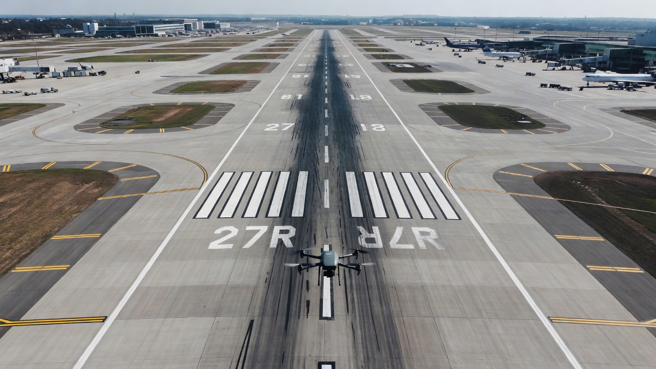
Flight Planning for Runway Inspection
Runway inspection requires specific considerations due to the safety-critical nature of airport pavements. Detecting cracks, Foreign Object Debris (FOD), rubber deposits, lighting damage, and pavement deterioration demands extremely high geometric accuracy. Runway lengths typically range from 1,500 to 4,000 meters (4,900 to 13,000 feet) with widths of 23 to 60 meters (75 to 200 feet).
Flight Planning Parameters for Runways
The mission type should be a corridor or linear mission flown along the runway centerline. Altitude should be set to 30-60 meters AGL for crack detection or 60-100 meters for general condition surveys. GSD targets are 0.5-1.5 cm/pixel for crack detection and 2-3 cm/pixel for general condition surveys. Overlap should be 80 percent front and 70-75 percent side for comprehensive coverage. The gimbal angle should be -90 degrees (nadir) for orthomosaic generation and -45 degrees oblique for vertical features such as runway edge lights. Flight speed should be 3-5 meters per second, slower for higher resolution and higher overlap. A double grid or crosshatch pattern is beneficial for 3D modeling of the runway surface.
Special Considerations for Runway Operations
Airspace coordination with Air Traffic Control is mandatory. A NOTAM must be issued for drone operations near active runways. The operator must coordinate with airport operations for runway closure or activity scheduling. BVLOS is typically required for full-length runway coverage, necessitating a waiver under Part 107. Electromagnetic interference (EMI) from airport radar and navigation aids may affect the drone’s compass and GPS. Wildlife hazards and FOD must be checked before flight. An emergency landing zone must be identified before takeoff. Runway inspection missions require the highest level of pre-flight planning and safety coordination of any infrastructure inspection type.
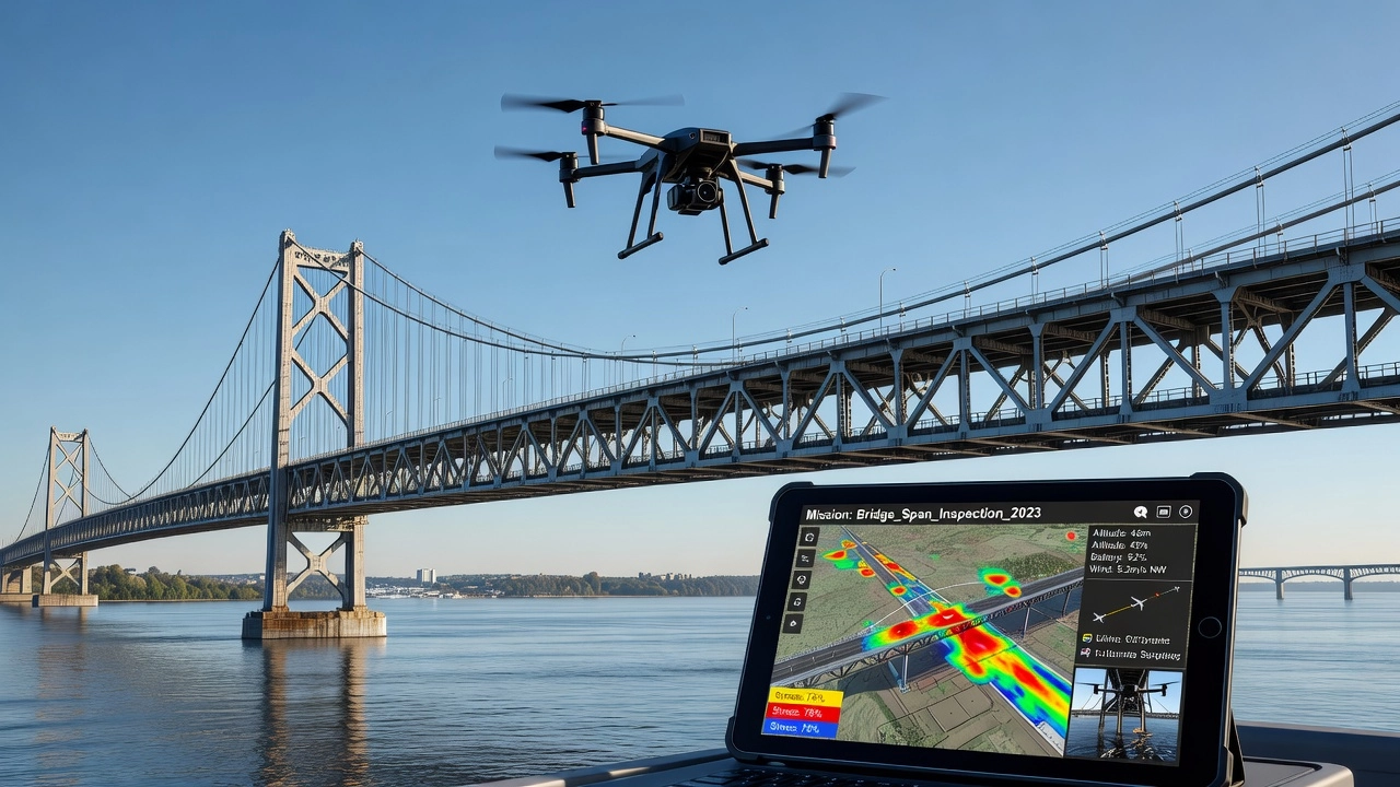
Flight Planning for Bridge Inspection
Bridge inspection using drones is one of the most demanding infrastructure inspection applications, requiring coverage of both the top deck and the complex substructure below. Academic research published by PMC (PMC10459964 — flight path study on Blessington Bridge) and FHWA research (FHWA-HRT-21-086) have established specific parameters for effective bridge inspection.
Research Findings
UAV altitude and camera angle most strongly affect data density and uniformity. A minimum of 66 percent overlap is required for successful 3D reconstruction, while 77 percent overlap achieves the highest coverage in bridge studies. Multiple flight paths improve local geometric accuracy more than simply increasing overlap percentage. Critically, no single set of flight parameters is optimal for every data collection goal — the parameters must be tailored to the specific bridge type, condition, and inspection requirements.
Bridge Deck — Top Surface
For the bridge deck or top surface, a 2D grid or double grid mission type is used. Altitude should be 20-50 meters AGL depending on the required crack-detection resolution. GSD targets are 2-5 cm/pixel for condition surveys and 0.5-2 cm/pixel for crack mapping. Overlap should be 75-80 percent front and 65-75 percent side with the gimbal at -90 degrees (nadir).
Bridge Substructure — Under-Deck, Piers, and Abutments
The substructure presents the most significant challenges for drone inspection. Mission type is custom 3D waypoint or vertical facade mapping. The primary challenge is GNSS shadowing under the bridge deck, which creates a GPS-denied environment. Solutions include visual positioning systems (VIO), pre-programmed waypoint missions initiated before flying under the deck, and manual flight in GPS-denied areas with VIO assist. Distance from the structure should be 3-10 meters with a gimbal angle of 0 to -45 degrees (horizontal to oblique depending on the target). Overlap should be 80 percent or higher for reliable Structure from Motion (SfM) reconstruction in complex geometry.
Bridge Piers and Columns
Orbital or POI missions are flown around each pier with an orbit radius of 5-15 meters depending on pier width. Multiple orbital passes are conducted at different height layers with a gimbal pitch of -45 degrees for oblique coverage.
Key Challenges
GPS multipath and reflections occur near steel bridge structures. GNSS shadowing under the deck creates navigation difficulties. Confined spaces between girders limit drone maneuverability. Traffic below the bridge creates safety concerns. Wind turbulence around the bridge superstructure affects flight stability. DroneBlocks research from Purdue University has developed automated flight paths specifically for under-deck inspection using visual programming approaches.
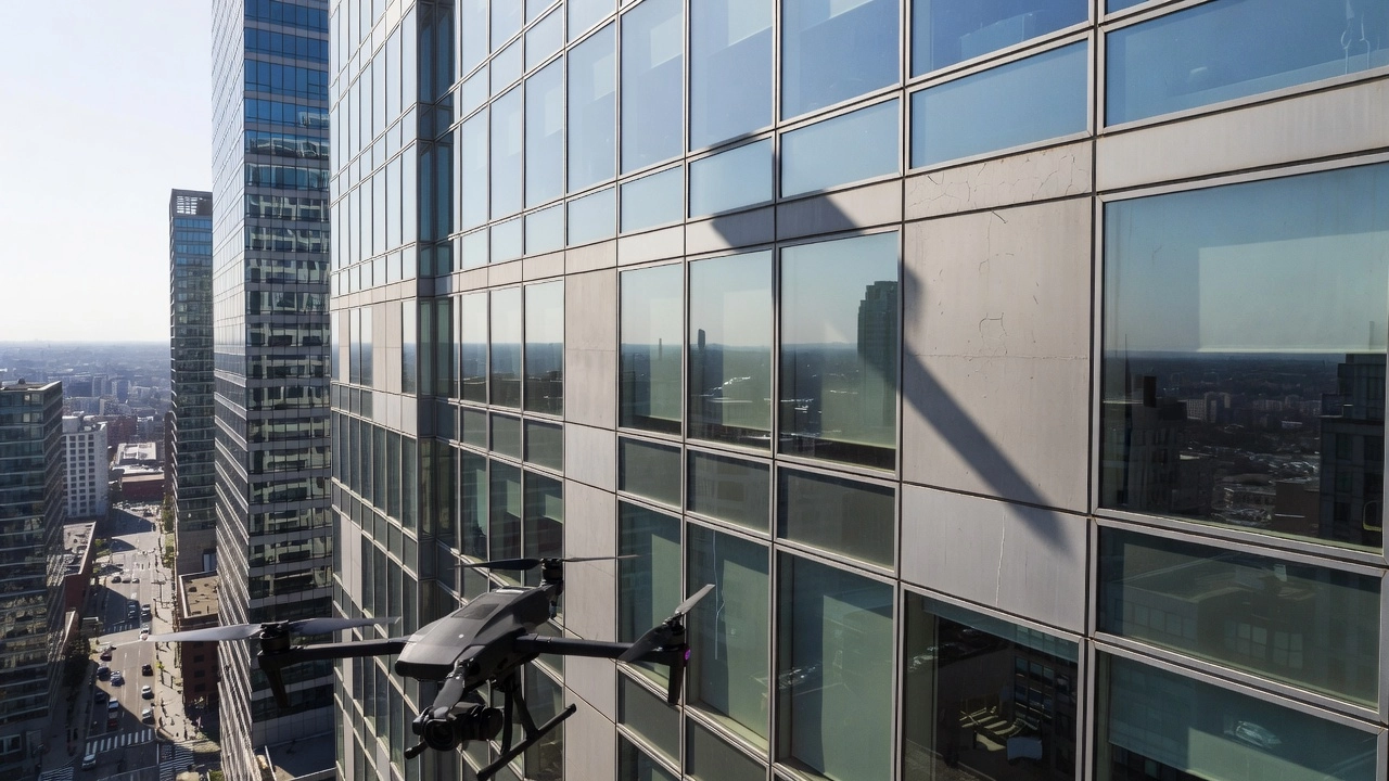
Flight Planning for Building Inspection
Building and facade inspection using drones has become the preferred method over traditional scaffolding and crane-based approaches due to significant cost savings and improved safety.
Facade Mapping Parameters
For vertical surface mapping, a vertical zigzag pattern (facade mode) is flown along the building face. Distance to the object should be 5-20 meters depending on building height and camera resolution. Vertical spacing between passes should be 5-15 meters to ensure 60-70 percent vertical overlap. The gimbal pitch is set to 0 degrees (horizontal, aimed at the building surface). Flight speed is limited to 1-3 meters per second for detailed capture.
Orbital Passes for Comprehensive Coverage
Orbital passes are flown around the building for corners and comprehensive 3D coverage. Orbit radius is set from the building center with one pass per 4-8 floors typically. Altitude step between orbital passes is 10-20 meters with a gimbal pitch of -45 degrees for oblique shots capturing both the facade and roof line.
Recommended Cameras and Settings
Enterprise drones recommended for building inspection include the DJI Matrice 350 RTK with Zenmuse P1 (full-frame 45MP) or H20T, and the Mavic 3 Enterprise with its 20MP 4/3 CMOS sensor and 4K video. Camera settings should be ISO 100-400, shutter speed 1/500 to 1/1000 second, and manual white balance. Best results come from videogrammetry using 4K at 30 fps minimum with overlapping passes.
Regulatory and Safety Considerations for Facade Inspection
Under FAA Part 107, the maximum altitude of 400 feet AGL is sufficient for most mid-rise buildings. For buildings over 400 feet, the operator must stay within 400 feet horizontally of the structure to qualify for the above-400-foot allowance. Urban operations require consideration of pedestrians below — street closures may be needed. Privacy considerations apply when windows and tenants are visible. An emergency landing plan must be established for the urban environment where safe landing zones are limited. Building inspection in urban environments demands the highest level of pilot situational awareness and pre-planning.
Mission Execution and Monitoring
Live Telemetry
Real-time data streamed during flight includes position (GPS/RTK coordinates, HDOP, satellite count), attitude (roll, pitch, yaw), velocity (ground speed, vertical speed), battery (voltage, percentage remaining, current draw, remaining flight time), radio link (RC signal strength, video signal strength, data link quality), and distance (distance from home, distance traveled).
Best practices for telemetry monitoring include continuous observation — most accidents give advance warning through telemetry anomalies. HDOP should be monitored with a target under 1.0 for RTK and under 2.5 for standard GPS. Battery reserve should maintain 20-30 percent minimum for safety margin, with low-battery failsafe set to RTH at 25-30 percent and auto-land at 10-15 percent.
Return-to-Home (RTH)
RTH can be triggered by pilot command (manual RTH), low battery warning, signal loss (RC link timeout), geofence breach, or failsafe activation. The RTH altitude must be set higher than all obstacles in the flight area — typically 50-100 meters AGL depending on local obstacles — and must consider terrain between the current position and home. Behavior options include RTH, hover, or land on signal loss. Landing options include precision landing using a visual marker or standard landing.
Geofencing
Geofencing creates a virtual perimeter that restricts drone flight. Cylindrical geofencing (Mission Planner, PX4) is centered on the home position and defined by maximum radius and altitude. Polygon geofencing (UgCS, DroneDeploy) allows drawing custom boundaries on the map. Actions on breach include warn pilot, hover in place, auto-RTH, or land immediately. Geofencing is critical for airport proximity operations, urban operations, and property boundary compliance.
Failsafe Configuration
Condition
Action Options
RC signal loss
Hover, RTH, Land, Disarm
Battery low (Stage 1)
Warning only
Battery low (Stage 2)
RTH triggered
Battery critical (Stage 3)
Immediate landing
Geofence breach
Warn, RTH, Land
GPS loss
Hover (if not needed), Land
Altitude limit breach
Hold altitude, RTH
Mission Contingency Planning
Abort criteria must be defined before flight. A minimum of one spare battery should be on-site. Emergency landing zones must be identified. A secondary takeoff and landing site should be designated if the primary site is compromised. A communication plan with the crew and stakeholders must be established. UgCS recommends simulating the entire flight before going to the field.
Post-Mission Workflow
After completing the inspection mission, the operator should review telemetry logs for anomalies, verify image and video quality (checking focus, exposure, and coverage), back up data to redundant storage, charge batteries for the next flight, perform a post-flight inspection checking for damage, clean the camera lens, and remove props if damaged. Complete the flight log and documentation for compliance purposes.
The post-mission analysis phase involves processing the captured imagery through photogrammetry software to generate orthomosaics, point clouds, 3D meshes, and inspection reports. Consistent flight planning ensures that data from periodic inspections is directly comparable, enabling trend analysis and predictive maintenance planning. This repeatability is the fundamental value proposition of structured drone flight planning — without it, comparative analysis across time series data is unreliable.
Summary of Key Numerical Standards
Parameter
Standard Range
Critical Notes
Frontal Overlap (frontlap)
75-85%
66% minimum for 3D reconstruction
Side Overlap (sidelap)
60-75%
77% optimal for bridge deck coverage
GSD for crack detection
0.5-2 cm/pixel
Depends on altitude and sensor
Mapping altitude
50-120 m AGL
FAA max 400 ft (122 m)
Flight speed (mapping)
3-8 m/s
Coordinate with capture interval
Flight speed (facade)
1-3 m/s
Slow for detailed vertical passes
Shutter speed
1/500s minimum
1/1000s+ for motion blur reduction
ISO
100-400
Max 800 with auto-ISO
RTH altitude
50-100 m AGL
Must exceed all obstacles
Battery landing threshold
20-30%
Critical safety margin
Terrain follow altitude (DJI)
30-200 m AGL
RTK required for minimum 25 m
Drone flight planning for infrastructure inspection is a multidisciplinary discipline combining aeronautical engineering, photogrammetry, sensor physics, regulatory compliance, and operational safety. The quality of the inspection data — and ultimately the value of the inspection — is determined almost entirely by the quality of the flight planning that precedes it. As the drone flight planning software market continues to grow and as regulatory frameworks evolve to enable more complex BVLOS operations, the capabilities and applications of drone-based infrastructure inspection will continue to expand, making structured flight planning an increasingly critical skill for inspection professionals across all infrastructure sectors.
Frequently Asked Questions
Drone flight planning for infrastructure inspection is the process of designing automated flight paths (waypoint missions) with optimized parameters — altitude, speed, overlap, gimbal angle, and camera settings — to capture consistent, repeatable, high-quality inspection imagery. It ensures uniform Ground Sampling Distance (GSD), sufficient image overlap for photogrammetric reconstruction, regulatory compliance, and safety during missions over bridges, runways, buildings, pipelines, and other infrastructure assets.
The six primary mission types are: (1) 2D Grid Missions for orthomosaic mapping of flat areas; (2) Corridor/Linear Missions for pipelines, power lines, and runways; (3) Orbital/POI Missions for towers, wind turbines, and bridge piers; (4) Facade Mapping Missions for building exterior inspections; (5) 3D Waypoint Missions for complex structures requiring full control over each camera position; and (6) Panorama Missions for 360-degree overview documentation.
Frontal overlap (frontlap) of 75-85% and side overlap (sidelap) of 60-75% are standard. The minimum threshold for successful 3D reconstruction is 66% overlap. For detailed bridge deck inspections, 77% overlap achieves the highest coverage. Increasing overlap beyond 85% yields diminishing returns in accuracy while significantly increasing flight time and processing load.
Under FAA Part 107, the altitude limit is 400 ft (122 m) AGL in uncontrolled airspace, maximum speed is 100 mph, VLOS must be maintained, and 3 statute miles visibility is required. EASA Open Category limits operations to 120 m AGL with no operational authorization needed for low-risk flights. Infrastructure inspections typically fall under specific or certified categories requiring operational authorization. LAANC provides near-instant airspace authorization in controlled zones.
Terrain following adjusts the drone's altitude above ground level (AGL) to maintain consistent distance from the terrain surface, ensuring uniform GSD and overlap across variable topography. Without it, a drone flying at constant AMSL altitude over hilly terrain produces higher resolution on hilltops and lower resolution in valleys, with potential coverage gaps. DJI Pilot 2 supports real-time terrain follow from 30-200 m AGL using imported DTM/DSM GeoTIFF files with RTK positioning.
Optimize Your Infrastructure Inspections
Leverage professional drone flight planning for precise, repeatable, and compliant infrastructure inspections. Contact us to learn how our solutions can streamline your inspection workflows.
Automated drone inspection uses pre-programmed flight paths, computer vision, and AI analysis to survey infrastructure assets including runways, bridges, roads,...
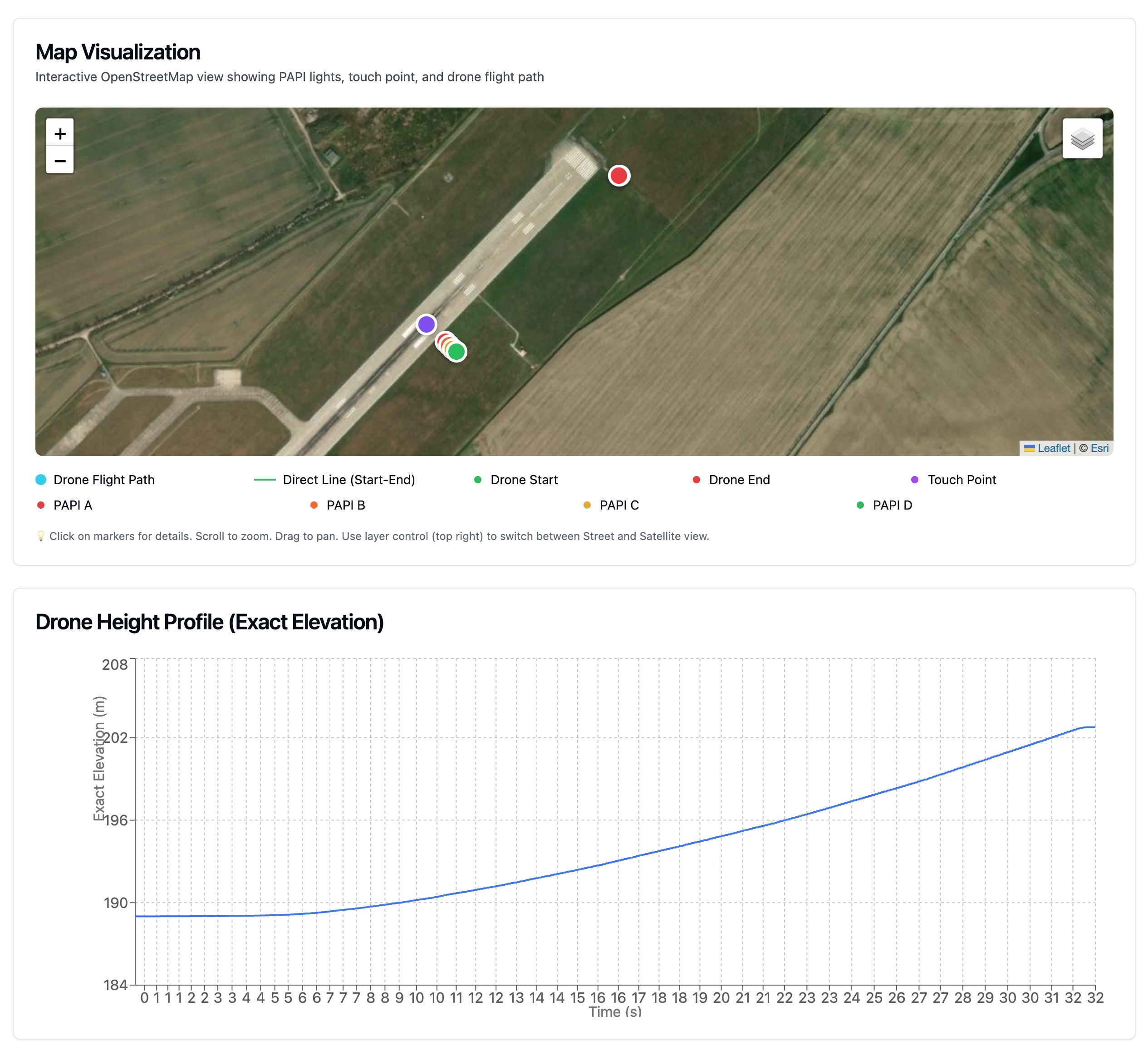
The Operational Benefits of Drone-Based PAPI Inspection: A Game-Changer for Airport Maintenance
Discover how drone technology is revolutionizing PAPI light inspection with superior efficiency, safety, and cost-effectiveness compared to traditional flight i...
9 min read
PAPI inspection
drone technology
+3
Cookie Consent We use cookies to enhance your browsing experience and analyze our traffic. See our privacy policy.