Frost Heave
Frost heave is the upward displacement of pavement surfaces caused by ice lens formation in frost-susceptible subgrade soils during freezing conditions. The phe...
39 min read
Geotechnical
Pavement engineering
+5
Freeze-thaw damage is the progressive deterioration of concrete caused by repeated cycles of water freezing and expanding within the concrete pore structure. Without adequate air entrainment, freeze-thaw cycles cause scaling, cracking, and eventual disintegration. Covers the mechanism, critical role of air entrainment, visual indicators, severity assessment, and cold-climate airport pavement inspection considerations.
Freeze-thaw damage is a physical deterioration process that occurs when water-saturated concrete is subjected to repeated cycles of freezing and thawing. The mechanism begins at the microscopic level within the hardened cement paste, which contains a complex network of pores of varying sizes. These include gel pores (0.5 to 10 nanometers in diameter), capillary pores (10 nanometers to 10 micrometers), and entrained or entrapped air voids (0.01 to 1.0 millimeters and larger). The distribution and saturation state of these pores determine the concrete’s susceptibility to freeze-thaw damage.
When the ambient temperature drops below freezing, ice formation begins in the larger capillary pores first, as the freezing point of water is depressed in smaller pores due to surface tension effects. Water undergoes a volume expansion of approximately 9 percent upon freezing. If the capillary pores are more than 91.7 percent saturated with water — a condition known as critical saturation — there is insufficient space within the pore to accommodate this expansion. The result is that unfrozen water is expelled from the freezing zone, generating hydraulic pressure that propagates through the pore network.
The magnitude of this hydraulic pressure depends on several factors: the rate of freezing (faster freezing generates higher pressure), the permeability of the cement paste (lower permeability restricts water flow and increases pressure), the distance to the nearest air void or free surface, and the viscosity of the pore solution. When the hydraulic pressure exceeds the tensile strength of the cement paste (typically 2 to 4 MPa), microcracks form, propagating through the paste and around aggregate particles. Each subsequent freeze-thaw cycle widens and extends these microcracks, leading to progressive deterioration.
The damage is cumulative and irreversible. After a sufficient number of cycles, the microcracks coalesce into visible cracking, the surface layer begins to scale and delaminate, and the overall integrity of the pavement is compromised. In airport pavements, the combination of aircraft loading, deicing chemical exposure, and moisture from precipitation or groundwater creates particularly aggressive freeze-thaw conditions. The deterioration rate is accelerated when deicing salts are present, as these chemicals increase the degree of saturation of concrete through osmotic effects and hygroscopic moisture attraction.
Two principal theoretical frameworks explain the mechanism of freeze-thaw damage in concrete: the hydraulic pressure theory and the osmotic pressure theory. Both were developed by T.C. Powers and his colleagues beginning in the 1940s, and together they form the scientific foundation for understanding freeze-thaw deterioration and the role of air entrainment.
The hydraulic pressure theory, proposed by Powers in 1945, states that freeze-thaw damage results from the buildup of hydraulic pressure as water freezes within capillary pores. When water in a capillary pore begins to freeze, it expands by 9 percent, pushing unfrozen water ahead of the advancing ice front. This displaced water must flow through the surrounding pore network to find accommodation space. The resistance to this flow generates hydraulic pressure according to Darcy’s Law: the pressure gradient Δh equals the fluid viscosity η divided by the permeability k of the cement paste, multiplied by the flow rate Q and the flow path length l, divided by the flow area A.
The critical parameter in this theory is the maximum permissible flow distance — the distance unfrozen water must travel before reaching a relief point such as an air void or a free surface. Powers calculated that if this distance exceeds approximately 0.20 millimeters, the hydraulic pressure will exceed the tensile strength of the cement paste, causing local failure. This value became the basis for the widely accepted spacing factor requirement of 0.20 mm or less for freeze-thaw durable concrete.
The hydraulic pressure generated is directly proportional to the freezing rate. Under rapid freezing conditions, as encountered in laboratory tests such as ASTM C666, the hydraulic pressure can be substantially higher than under slow natural freezing. This explains why some concretes perform adequately in service but fail accelerated laboratory freeze-thaw tests. The theory also explains why low-permeability concretes — those with low water-cement ratios or high supplementary cementitious material contents — can be more susceptible to hydraulic pressure damage if they lack adequate air entrainment, because the reduced permeability restricts the flow of displaced water.
Powers and Helmuth extended the understanding of freeze-thaw damage in 1953 with the osmotic pressure theory, which addresses phenomena that could not be fully explained by hydraulic pressure alone. This theory recognizes that the pore solution in concrete is not pure water but a dilute electrolyte solution containing dissolved ions from the cement and any chemical admixtures.
When ice forms in a capillary pore, it consists of pure water crystals — the dissolved ions are excluded from the ice structure and concentrate in the remaining unfrozen pore solution. This creates a concentration gradient between the freezing capillary (high solute concentration) and the adjacent gel pores (lower solute concentration). Thermodynamics drive water molecules from the gel pores toward the capillary to equalize concentrations through osmotic diffusion.
This osmotic water movement can continue even after the capillary pore is completely filled with ice and concentrated solution, generating additional pressure as water is drawn toward the freezing site. The process is self-reinforcing: more water arrives, freezes, further concentrates the solution, and draws even more water. The resulting osmotic pressure can be substantial and can cause damage even in concretes that are not critically saturated at the onset of freezing.
The practical implication is that concrete may suffer freeze-thaw damage at lower saturation levels than predicted by the hydraulic pressure theory alone, particularly when deicing salts or other soluble chemicals are present. Air voids serve as pressure relief sites for both hydraulic and osmotic pressure mechanisms, providing space for expelled water and accommodating the volume changes associated with ice formation.
A related concept, also developed by Powers, is the critical saturation theory, which states that concrete will only suffer freeze-thaw damage when the capillary pores are more than 91.7 percent saturated with water. This threshold derives from the 9 percent volume expansion of freezing water: if the pores are less than 91.7 percent full, the expanding ice can occupy the existing empty space within the same pore without generating pressure. Once the saturation exceeds 91.7 percent, however, the expanding ice must displace into adjacent pores or create cracks.
Modern research has refined this concept, suggesting that the critical degree of saturation for freeze-thaw damage onset is approximately 86 percent under many field conditions. Factors that increase the degree of saturation over time — such as poor drainage, high groundwater tables, and deicing chemical exposure — progressively move the concrete toward the critical threshold, explaining why freeze-thaw damage often appears only after several years of service.
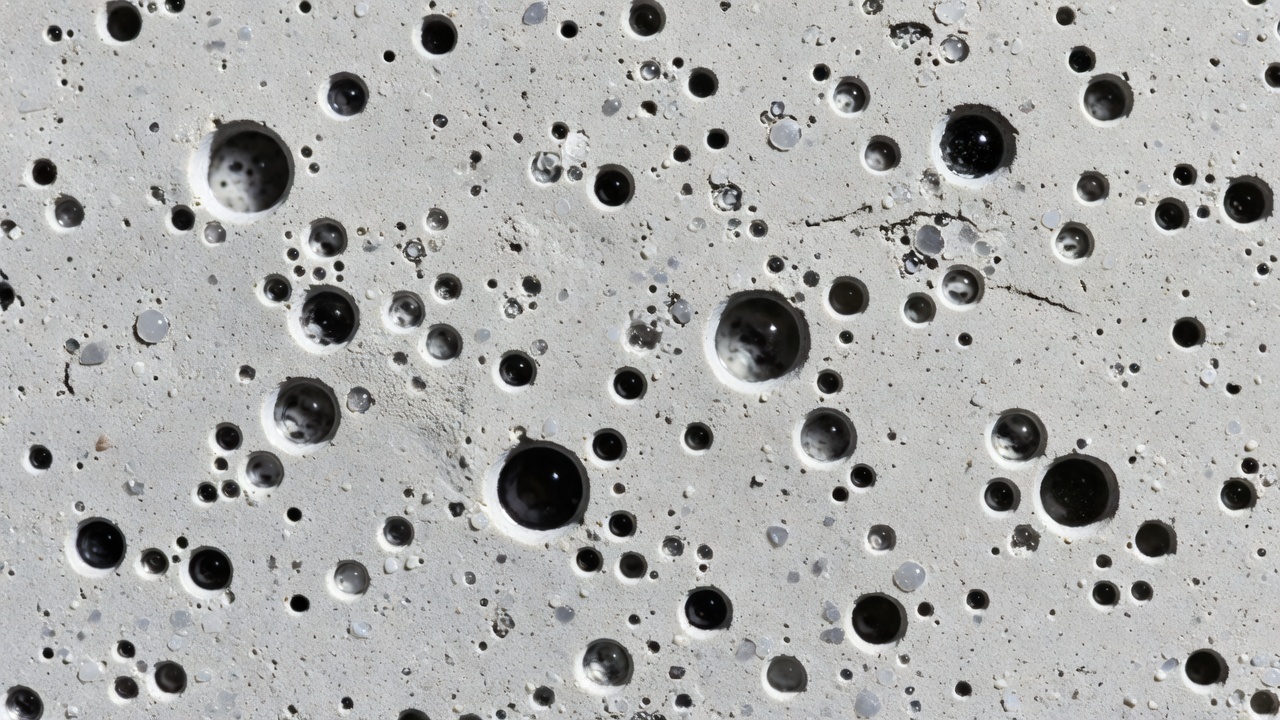
Air entrainment is the single most effective and widely used method for protecting concrete against freeze-thaw damage. It involves the deliberate incorporation of millions of microscopic, spherical air voids into the concrete paste through the use of air-entraining admixtures (AEAs). These voids, typically ranging from 0.01 to 1.0 millimeters in diameter, remain in the hardened concrete and provide critical pressure relief during freezing events.
The mechanism of protection is conceptually straightforward. When water in a capillary pore freezes and expands, the displaced unfrozen water can flow into the nearest entrained air void rather than building up damaging hydraulic pressure. The air voids are typically empty or only partially filled with water under normal service conditions because they are the last pores to saturate. They function as internal expansion chambers that accommodate the 9 percent volume increase of freezing water.
For the air void system to be effective, three parameters must be properly controlled:
Spacing factor is the most critical parameter. It represents the maximum distance any point in the cement paste must travel to reach an air void. The widely accepted maximum spacing factor for freeze-thaw durability is 0.200 mm (0.008 inches) . When the spacing factor exceeds this threshold, the hydraulic and osmotic pressures generated during freezing exceed the tensile strength of the paste before the displaced water can reach a relief void. Concretes with spacing factors below 0.200 mm generally exhibit durability factors above 80 percent in ASTM C666 testing.
Specific surface is the ratio of the total surface area of air voids to their total volume, expressed in mm²/mm³ or in²/in³. A higher specific surface indicates a larger number of smaller voids for the same total air volume. The minimum recommended specific surface is 24 mm²/mm³ (600 in²/in³) . A high specific surface is essential because small, closely spaced voids provide more efficient protection than large, widely spaced voids with the same total air content.
Total air content is the most commonly specified and measured parameter, typically determined on fresh concrete using the pressure method (ASTM C231 / AASHTO T 152). For concrete exposed to freeze-thaw conditions, the recommended total air content ranges from 5 to 8 percent depending on the nominal maximum aggregate size and exposure severity. The American Concrete Institute (ACI 318) specifies the following air contents for freeze-thaw exposure classes:
| Nominal Maximum Aggregate Size | Air Content for Severe Exposure (F2/F3) |
|---|---|
| 9.5 mm (3/8 in) | 7.5% |
| 12.5 mm (1/2 in) | 7.0% |
| 19.0 mm (3/4 in) | 7.0% |
| 25.0 mm (1 in) | 6.5% |
| 37.5 mm (1-1/2 in) | 6.5% |
| 50.0 mm (2 in) | 6.0% |
| 75.0 mm (3 in) | 5.5% |
A field tolerance of ±1.5 percent is typically applied to these target values.
Air-entraining admixtures are surfactants (surface-active agents) that stabilize air bubbles during concrete mixing. The most common AEAs include Vinsol resin (a natural wood resin extract, historically the first widely used AEA), synthetic detergents such as alkylarylsulfonates and alkylsulfates, sulfonated hydrocarbons, and fatty and resinous acids. These molecules have a hydrophilic (water-attracting) polar head and a hydrophobic (water-repelling) hydrocarbon tail, which align at the air-water interface to reduce surface tension and stabilize the bubbles against coalescence.
The dosage of AEA required to achieve the target air content depends on multiple factors: the cement type and fineness, the aggregate grading and shape, the concrete temperature, the mixing energy and duration, the presence of other chemical admixtures (particularly superplasticizers), and the organic content of the mix water. In general, higher temperatures, finer cements, and the presence of polycarboxylate-based superplasticizers increase the AEA demand. The air content should be verified frequently during production, as overdosage can reduce strength while underdosage compromises freeze-thaw protection.
A significant challenge in achieving durable air-entrained concrete is maintaining air void system stability from the batching plant through placement and consolidation. Air loss of 1 to 2 percent is common during pumping, transport, and vibration. This loss typically affects the larger, less stable bubbles, which are also the least effective for freeze-thaw protection. However, if the total air content drops below the target range, the spacing factor may increase beyond the critical threshold.
Field testing of fresh concrete air content using ASTM C231 should be performed at the point of placement, not just at the plant. The Super Air Meter (SAM) , standardized under AASHTO TP 118, provides a more comprehensive assessment of air void quality in fresh concrete by determining a SAM Number correlated with the spacing factor. SAM Numbers below 0.2 psi are generally associated with adequate freeze-thaw protection.
Freeze-thaw damage manifests through several characteristic visual distress patterns on concrete pavement surfaces. These visual indicators allow inspectors to identify the presence, type, and severity of freeze-thaw deterioration during routine pavement condition surveys conducted in accordance with ICAO and FAA guidelines.
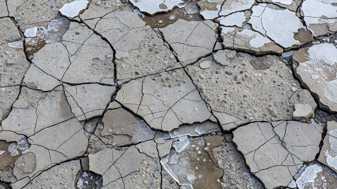
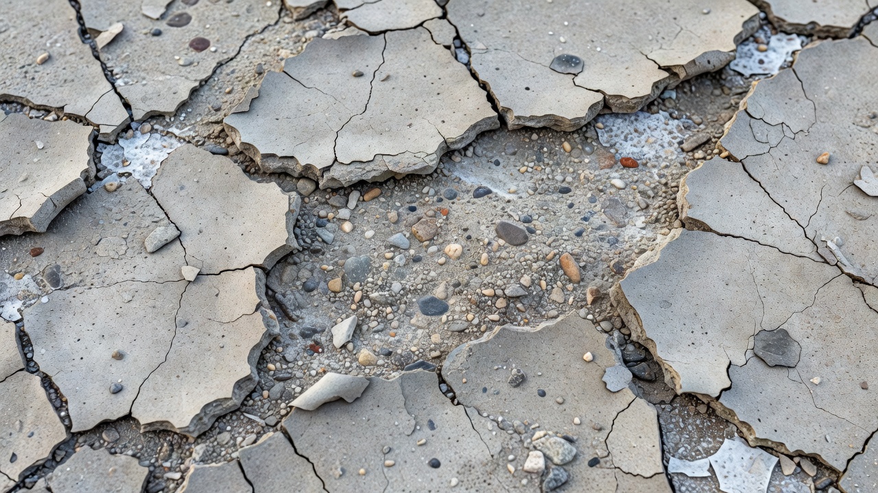
Scaling is the most commonly observed form of freeze-thaw deterioration on concrete pavement surfaces. It involves the progressive loss of the surface mortar (cement paste and fine aggregate) over an area typically ranging from localized spots to large continuous patches. Scaling proceeds through recognizable stages: light scaling involves loss of surface mortar up to approximately 5 mm depth with coarse aggregate remaining exposed but intact; moderate scaling shows loss of mortar to 5 to 10 mm depth with coarse aggregate clearly exposed and some aggregate particles beginning to loosen; severe scaling involves surface loss exceeding 10 mm with significant aggregate loss and a rough, pitted surface texture; and very severe scaling results in loss of surface material exceeding 20 mm requiring immediate repair action.
Scaling is particularly prevalent at pavement joints and free edges, where moisture ingress is greatest and where deicing chemicals accumulate. The presence of deicing salts dramatically accelerates scaling by increasing the degree of saturation of the concrete surface layer, promoting osmotic pressure generation, and subjecting the concrete to thermal shock when salt-laden snow and ice melt at temperatures below 0°C.
D-cracking (durability cracking) is a distinctive form of freeze-thaw deterioration that initiates within the coarse aggregate particles rather than in the cement paste. It occurs when certain aggregates — particularly limestones, dolomites, and some gravels — contain a pore structure that is susceptible to critical saturation and freeze-thaw expansion. The name derives from the characteristic D-shaped or crescent-shaped crack pattern that forms parallel to transverse and longitudinal joints and free slab edges.
D-cracking begins in the lower portion of the concrete slab where moisture is most abundant due to capillary rise from the subbase. Cracks initiate within the aggregate particles and propagate outward into the surrounding mortar. As deterioration progresses, cracks extend parallel to the joint face, creating a series of closely spaced, hairline cracks that form a darkened band adjacent to the joint. In advanced stages, the cracking progresses toward the slab center, and the joint area becomes severely fractured with spalling and disintegration of the concrete.
The Iowa Pore Index test was specifically developed to evaluate aggregate susceptibility to D-cracking. Aggregates with intermediate pore sizes (0.04 to 0.20 μm) are most susceptible because surface tension limits water movement out of the pores during freezing, yet the pores are large enough to accommodate significant water absorption. The only reliable preventive measure is to avoid using D-cracking susceptible aggregates or to limit the maximum aggregate size to reduce stress concentrations.
Map cracking (also known as pattern cracking or alligator cracking) refers to a network of interconnected cracks dividing the concrete surface into small polygonal fragments resembling a roadmap or alligator skin. This pattern results from differential volume changes within the concrete during freezing and thawing cycles. The surface layer contracts and expands at a different rate than the underlying concrete due to moisture and temperature gradients, creating tensile stresses that cause the surface to crack in a random pattern.
Map cracking is particularly common in concrete that has been subjected to surface drying followed by rapid freezing, or in concrete with a high water-cement ratio that exhibits greater drying shrinkage. The cracks typically penetrate only a few millimeters to centimeters into the surface and may not extend through the full slab depth. In freeze-thaw damaged pavements, map cracking often appears as a precursor to more extensive scaling and surface disintegration.
Popouts are small, conical depressions on the concrete surface, typically 5 to 50 mm in diameter, caused by the expansion and fracture of individual aggregate particles near the surface. When a susceptible aggregate particle absorbs water and freezes, the expansion forces a cone of surface mortar to detach, leaving a characteristic shallow depression with the fractured aggregate particle visible at the bottom. Popouts are primarily a cosmetic defect in most pavements, but in large numbers they can indicate a broader aggregate durability problem and may progress to more extensive surface deterioration.
Laboratory testing of freeze-thaw resistance is essential for qualifying concrete mixtures, evaluating aggregate suitability, and conducting forensic investigations of pavement failures. The primary standard for evaluating freeze-thaw resistance in the United States and internationally is ASTM C666, Standard Test Method for Resistance of Concrete to Rapid Freezing and Thawing.
ASTM C666 specifies two procedures. Procedure A: Rapid Freezing and Thawing in Water involves subjecting concrete beam or prism specimens (typically 75 × 100 × 400 mm or 100 × 100 × 400 mm) to repeated cycles of freezing and thawing while completely submerged in water. Each cycle consists of lowering the specimen temperature from 4°C to -18°C and then raising it back to 4°C over a period of 2 to 5 hours. Procedure B: Rapid Freezing in Air and Thawing in Water is similar but the freezing portion of the cycle occurs in air while thawing occurs in water. Procedure A is generally considered more aggressive and is more commonly specified.
The test measures the fundamental transverse frequency of the specimen at intervals of no more than 36 cycles, using ASTM C215, Standard Test Method for Fundamental Transverse, Longitudinal, and Torsional Frequencies of Concrete Specimens. The relative dynamic modulus of elasticity (RDM) is calculated as the square of the ratio of the fundamental frequency at any test interval to the initial frequency at zero cycles. The test continues until the RDM drops below 60 percent of the initial value, or until 300 cycles have been completed.
The durability factor (DF) is calculated as DF = P × N / M, where P is the RDM at N cycles expressed as a percentage, N is the number of cycles at which P reaches 60 percent (or M if 60 percent is not reached), and M is the specified number of cycles (typically 300). A DF of 80 percent or higher is generally considered indicative of adequate freeze-thaw resistance.
ASTM C666 is an accelerated test that does not directly predict field service life. The freezing rate in the test (typically one cycle every 2 to 5 hours) is much faster than natural freezing, which can overstress some mixtures relative to their field performance. Conversely, the constant saturation of specimens in water may underestimate some field deterioration mechanisms, particularly those involving deicing salts. The test is most valuable as a comparative tool for evaluating the relative freeze-thaw resistance of different concrete mixtures or aggregates.
ASTM C672, Standard Test Method for Scaling Resistance of Concrete Surfaces Exposed to Deicing Chemicals, evaluates surface scaling resistance by subjecting concrete slabs to cycles of freezing and thawing while a 4 percent calcium chloride solution covers the surface. Scaling is assessed visually on a scale from 0 (no scaling) to 5 (severe scaling with coarse aggregate visible over the entire surface).
ASTM C457, Standard Test Method for Microscopical Determination of Parameters of the Air-Void System in Hardened Concrete, provides the definitive characterization of air void parameters. A polished concrete section is examined under a microscope at 100× to 200× magnification, and the air void system is characterized through linear traverse or point-count methods. The test yields total air content, specific surface, spacing factor, and air void size distribution. Modern automated methods using the RapidAir 457 system significantly reduce the time and operator skill required for this analysis.
AASHTO T 161 is the equivalent of ASTM C666 in the AASHTO standards, commonly used by state highway agencies. ASTM C1646 provides a standard practice for evaluating the freeze-thaw resistance of coarse aggregates in air-entrained concrete.
Airport pavements in cold climates face unique freeze-thaw challenges that distinguish them from highway or general infrastructure pavements. The interaction of high aircraft loads, deicing chemical exposure, strict operational safety requirements, and demanding smoothness standards creates an environment where freeze-thaw damage can have serious operational consequences.
The heavy loads imposed by aircraft operations — with tire pressures exceeding 1.5 MPa (220 psi) for large commercial aircraft — generate tensile stresses at the bottom of the concrete slab that can interact with freeze-thaw induced microcracking. The combined effect of mechanical loading and freeze-thaw cycling accelerates deterioration beyond what either mechanism would produce alone. Research has shown that freeze-thaw cycles reduce the flexural fatigue life of concrete pavements by 30 to 60 percent, depending on the number of freeze-thaw cycles and the quality of the air void system.
Airport pavements receive intensive application of deicing and anti-icing chemicals including potassium acetate, sodium acetate, calcium magnesium acetate, and urea (increasingly restricted due to environmental concerns). These chemicals exacerbate freeze-thaw damage through multiple mechanisms: they increase the degree of saturation of the surface concrete by hygroscopic attraction; they create osmotic pressure gradients that drive additional water into the pore structure; they subject the concrete to thermal shock when large temperature differentials occur between the warm pavement surface and the freezing chemical mixture; and some chemicals can chemically attack the hydrated cement paste, particularly in the presence of freeze-thaw cycling.
The International Civil Aviation Organization (ICAO) and the Federal Aviation Administration (FAA) recognize freeze-thaw durability as a critical design parameter for airport pavements in cold climates. ICAO Annex 14, Volume I, and the associated Aerodrome Design Manual (Doc 9157, Part 3 — Pavements) emphasize the importance of durable concrete for runway and taxiway surfaces. The FAA’s Advisory Circular AC 150/5370-10, Standards for Specifying Construction of Airports, specifies air content requirements for air-entrained concrete in airport pavements.
Key specifications for airport pavement concrete in freeze-thaw environments include: minimum air content of 6.0 percent for concrete with 37.5 mm nominal maximum aggregate size, maximum water-cementitious materials ratio of 0.45, minimum 28-day compressive strength of 4,000 to 5,500 psi (depending on the pavement category), and air void spacing factor not exceeding 0.008 inches (0.200 mm) as verified by ASTM C457.
During airport pavement condition inspections in cold climates, freeze-thaw damage should be documented with specific attention to: the presence and severity of scaling at joints and slab edges, evidence of D-cracking (particularly near longitudinal and transverse joints), the extent of map cracking on slab surfaces, popout frequency, and the condition of joint sealants (damaged sealants accelerate moisture ingress). Inspectors should note the orientation of deterioration relative to prevailing winter wind directions and snow accumulation patterns, as these factors influence moisture distribution and freezing severity.
Freeze-thaw damage potential varies significantly across climate zones, from regions with few annual freeze-thaw cycles to those with hundreds of cycles per year. The number of annual freeze-thaw cycles — defined as the number of times the temperature crosses the freezing point of 0°C — is the primary climatic parameter used to assess exposure severity. In the United States, the FHWA divides regions into four freeze-thaw zones based on the average annual number of cycles: minimal (0 to 25 cycles), moderate (25 to 50 cycles), high (50 to 100 cycles), and severe (over 100 cycles).
However, the number of freeze-thaw cycles alone does not fully characterize the deterioration risk. The frost zone depth (the depth to which the ground freezes) and the duration of freezing periods are equally important. In regions with deep frost penetration, the entire pavement structure and subgrade may freeze, creating complex moisture migration patterns that can saturate the concrete from below even when the surface is protected. The freezing index — the cumulative number of degree-days below 0°C — provides a more comprehensive measure of freezing severity.
Airport pavements in the following regions require particular attention to freeze-thaw resistance: the northern United States (Minnesota, Wisconsin, Michigan, New York, and New England states), Canada (particularly the Prairie provinces, Ontario, Quebec, and the Maritime provinces), northern Europe (Scandinavia, the Baltics, northern Germany, Poland, and Russia), and high-altitude airports in mountainous regions worldwide (such as those in the Rocky Mountains, the Alps, the Andes, and the Himalayas).
At airports in severe freeze-thaw zones, mitigation measures beyond air entrainment are often necessary. These include the use of frost-resistant subbase materials, adequate pavement drainage to remove water before it can saturate the concrete, thermal insulation layers to reduce frost penetration, and increased pavement thickness to limit subgrade frost heave effects.
Assessing the severity of freeze-thaw damage is essential for prioritizing repairs, estimating remaining service life, and developing maintenance strategies. The FAA Pavement Condition Index (PCI) methodology, standardized under ASTM D5340, provides a systematic framework for quantifying pavement distress severity.
For freeze-thaw related distresses, severity is evaluated as follows:
Scaling Severity: Low severity scaling involves loss of surface mortar to a depth of less than 6 mm (0.25 inches), with coarse aggregate exposed but firmly embedded. Medium severity scaling extends to 6 to 12 mm (0.25 to 0.5 inches) with some aggregate loss and a moderately rough surface. High severity scaling exceeds 12 mm (0.5 inches) with extensive aggregate loss, a very rough surface, and possible exposure of reinforcing steel or dowel bars.
D-Cracking Severity: Low severity D-cracking is defined as closely spaced cracks with light staining or darkening at the joint, typically affecting a zone less than 300 mm (12 inches) from the joint face. Medium severity involves more extensive cracking extending 300 to 600 mm (12 to 24 inches) from the joint, with some crack spalling and possible loose fragments. High severity D-cracking extends more than 600 mm (24 inches) from the joint, with wide cracks, spalling, disintegration, and loss of load transfer across the joint.
Map Cracking Severity: Low severity map cracking consists of a tight, closed network of hairline cracks with no spalling along crack edges. Medium severity cracks show slight opening (1 to 3 mm) and minor spalling at crack intersections. High severity cracks are open (>3 mm), with significant spalling and loose fragments between crack polygons.
The rate of deterioration progression is an important consideration that is not captured in a single PCI survey. Repeated PCI surveys conducted at intervals of 1 to 3 years allow calculation of deterioration rates, which inform the urgency of repair interventions. Concretes with poor air entrainment typically show rapid deterioration progression once freeze-thaw damage initiates, while properly air-entrained concretes degrade more slowly when damage does occur.
Prevention of freeze-thaw damage begins at the mix design stage and continues through construction quality control. The primary preventive measures are: air entrainment, low water-cementitious materials ratio, use of supplementary cementitious materials, selection of frost-resistant aggregates, and proper construction and curing practices.
As discussed in detail in the dedicated section above, proper air entrainment is the most important preventive measure. The target air content should be specified based on the nominal maximum aggregate size and exposure class according to ACI 318 or equivalent national standards. The spacing factor should be verified on hardened concrete samples from the initial mix qualification and periodically during production using ASTM C457 or automated equivalent methods. The SAM Number offers a promising quality control tool for verifying air void quality in fresh concrete during construction.
A maximum water-cementitious materials ratio (w/cm) of 0.45 is typically specified for concrete exposed to freeze-thaw conditions. This limit reduces the capillary porosity of the hardened paste, decreasing both the rate of water absorption and the permeability of the concrete. Lower w/cm values (0.40 or less) provide additional protection, particularly when combined with supplementary cementitious materials. However, very low w/cm concretes require careful attention to curing to prevent plastic shrinkage cracking and to ensure adequate hydration.
The use of fly ash, ground granulated blast-furnace slag, and silica fume improves freeze-thaw resistance by refining the pore structure, reducing permeability, and increasing the chemical resistance of the paste. However, there are important caveats: mixtures with high fly ash dosages (typically above 25 percent) may have longer curing times before they develop adequate freeze-thaw resistance, and the air void system in mixtures with certain SCMs may be less stable, requiring higher AEA dosages to achieve the target air content. Silica fume at dosages of 5 to 10 percent can reduce the spacing factor by modifying the bubble size distribution.
Aggregate selection is critical for preventing D-cracking and aggregate-related freeze-thaw deterioration. Aggregates should be evaluated for freeze-thaw durability using relevant test methods: the Iowa Pore Index test for carbonate aggregates, ASTM C666 Procedure A on concrete specimens containing the aggregate, and ASTM C88 (soundness test using sodium or magnesium sulfate) as a screening tool. Aggregates with a known history of satisfactory freeze-thaw performance in similar climatic conditions are generally preferred.
Proper construction practices are essential for achieving the designed freeze-thaw resistance. Adequate curing — maintaining moisture and temperature conditions for cement hydration — is particularly critical for freeze-thaw durable concrete. The American Concrete Institute recommends curing for at least 7 days at temperatures above 10°C, and longer in cool weather. Concrete that is allowed to dry before adequate strength development will have a coarser pore structure, reduced air void system quality, and lower resistance to freeze-thaw cycling.
Other construction considerations include: uniform consolidation to eliminate honeycombing and large entrapped air voids, proper joint installation to facilitate water drainage away from the pavement, adequate pavement drainage through properly designed and maintained subbase and edge drainage systems, and protection from early freezing through the use of insulating blankets or heated enclosures when concrete is placed during cold weather.
When freeze-thaw damage has already occurred, repair options range from cosmetic surface treatments to full-depth slab replacement. The choice of repair strategy depends on the type, extent, and severity of the damage, as well as operational considerations at active airports.
Partial-depth repair is appropriate for localized scaling and surface deterioration that does not extend through the full slab depth. The procedure involves removing the damaged surface concrete to a depth of 25 to 75 mm (1 to 3 inches) by saw-cutting and chipping, cleaning the cavity, applying a bonding agent, and restoring the section with a compatible repair material. Polymer-modified cementitious mortars, low-shrinkage high-performance concrete, and fast-setting cementitious materials are commonly used for partial-depth repairs in airport pavements.
The key to successful partial-depth repair is ensuring adequate bond between the repair material and the existing concrete substrate. The substrate must be saturated surface-dry before placement, and the repair material must have low drying shrinkage to prevent debonding at the interface. Research has shown that more than 50 percent of partial-depth repairs on airport pavements require re-repair within 10 years, highlighting the importance of proper material selection and installation procedures.
Full-depth repair is necessary when freeze-thaw damage extends through the full slab thickness, as typically occurs with severe D-cracking, extensive scaling, or structural deterioration near joints. The procedure, as specified in FAA AC 150/5380-6C, involves saw-cutting full-depth around the repair area, removing the damaged concrete, preparing and compacting the subbase, installing dowel bars at transverse joints and tie bars at longitudinal joints, and placing and curing the new concrete.
For airports, full-depth repairs must restore the pavement to its original load-carrying capacity and surface smoothness. The repair concrete should match or exceed the freeze-thaw resistance of the original pavement, with proper air entrainment, a w/cm ratio of 0.45 or less, and adequate strength for early opening to traffic. Fast-track concrete mixtures using high early strength cement, accelerators, or polymer modifications can achieve opening strengths within 6 to 24 hours for emergency repairs.
For emergency repairs at active airports where immediate pavement restoration is required, pre-packaged rapid-setting polymer concrete and magnesium phosphate cement patches offer opening times of 1 to 4 hours. These materials are typically used for spall repairs at joints and localized deteriorated areas that pose a FOD (foreign object debris) hazard. Temporary patches are not a permanent solution and should be replaced with appropriate partial-depth or full-depth repairs within the same construction season.
The most cost-effective approach to managing freeze-thaw damage is preventive maintenance. Key preventive measures include: maintaining effective joint sealants to prevent water infiltration into the pavement structure, ensuring proper pavement drainage through cleaning and maintaining edge drains and subbase drainage systems, applying surface sealers (such as silanes or siloxanes) to reduce moisture absorption in susceptible pavements, and conducting regular PCI inspections to detect and document freeze-thaw damage at an early stage when repairs are most cost-effective.
At airports in severe freeze-thaw zones, a comprehensive pavement management system that tracks deterioration rates and schedules timely repairs is essential for maintaining operational safety and extending pavement service life. The FAA’s Pavement Management Program (PMP) guidelines (AC 150/5380-7) provide a framework for systematic pavement condition assessment and maintenance planning.
Ensure your airport pavements withstand freeze-thaw cycles with proper inspection, air entrainment verification, and timely repairs. TarmacView provides expert guidance and tools for assessing freeze-thaw damage and planning effective maintenance strategies.
Frost heave is the upward displacement of pavement surfaces caused by ice lens formation in frost-susceptible subgrade soils during freezing conditions. The phe...
D-cracking is a pattern of closely spaced crescent-shaped cracks near joints, edges, and cracks in PCC pavements, caused by freeze-thaw deterioration of suscept...
Concrete scaling is the deterioration of the upper pavement surface in Portland Cement Concrete (PCC) slabs, typically 3-13 mm deep, caused by freeze-thaw cycle...