Cathodic Protection (CP)
Cathodic protection is an electrochemical corrosion mitigation technique that prevents reinforcement corrosion in concrete structures by making the steel the ca...
21 min read
Reinforcement
Corrosion protection
+3
Galvanic anode cathodic protection for reinforced concrete uses sacrificial metals (zinc, aluminum alloys, magnesium) electrically connected to reinforcing steel to provide passive corrosion protection without external power. Covers embedded anodes in new construction, patch repair discrete anodes, surface-applied systems (zinc mesh, hydrogel, arc-sprayed zinc), design spacing, service life, consumption rate, and inspection procedures per ICAO, FAA, and NACE standards.
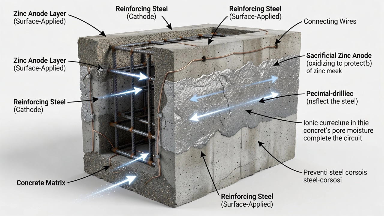
A galvanic anode — also referred to as a sacrificial anode — is a metallic component that provides cathodic protection (CP) to reinforcing steel in concrete structures through the electrochemical principle of dissimilar metal corrosion. The anode is manufactured from a metal that is more electrochemically active (less noble) than steel, meaning it has a more negative corrosion potential in the galvanic series. When electrically connected to the reinforcing bars and embedded in the same electrolyte (concrete pore water), a galvanic cell is established: the anode corrodes preferentially, releasing electrons that flow through the metallic connection to the steel reinforcing bars, driving the steel into a thermodynamically immune region where anodic dissolution cannot occur.
Unlike impressed current cathodic protection (ICCP) systems that require an external DC power source (rectifier) and permanent inert anodes such as mixed-metal-oxide (MMO) coated titanium mesh, galvanic anode systems generate their own protective current from the natural potential difference between the anode metal and steel. This makes them inherently passive, low-maintenance, and self-regulating — current output decreases as the steel becomes polarized and the potential difference narrows. The Federal Highway Administration (FHWA) has stated since 1982 that cathodic protection is the only rehabilitation technique that has proven to stop corrosion in salt-contaminated bridge decks regardless of the chloride content of the concrete, and galvanic anodes are one of the two fundamental CP implementation methods recognized in NACE SP0290 and ASTM G96 standards.
The operation of a galvanic anode in concrete is governed by the galvanic series in concrete pore water — a ranking of metals and alloys by their measured corrosion potential in alkaline (pH 12.5 to 13.5) environments. The galvanic series differs from the standard emf series because it reflects real-world potentials in the specific electrolyte, including the effects of surface films, aeration, and chloride concentration.
| Metal / Alloy | Typical Potential vs Cu/CuSO₄ (CSE) in Concrete | Behavior |
|---|---|---|
| Magnesium | −1,600 to −1,500 mV | Very active — rapid corrosion |
| Zinc (high purity, ASTM B418 Type II) | −1,100 to −950 mV | Active — suitable anode |
| Aluminum-Zinc-Indium alloy | −1,100 to −1,000 mV | Active — suitable anode |
| Steel (passive, uncorroded) | −200 to +100 mV | Noble — protected |
| Steel (active, corroding) | −600 to −350 mV | Intermediate |
| Copper | −200 to 0 mV | Very noble — not used |
When a zinc anode (≈ −1,050 mV CSE) is connected to corroding reinforcing steel (≈ −400 mV CSE), the driving voltage is approximately 650 mV. This voltage drives a protective current from the anode through the concrete electrolyte to the steel surface. The current density arriving at the steel must be sufficient to shift the steel potential in the negative direction by at least 100 mV (the 100 mV polarization decay criterion per NACE Standard RP0290-2000) or to achieve an instant-off potential more negative than −850 mV CSE.
The current output is governed by Ohm’s law: I = E / R, where E is the driving voltage (difference between anode and steel potential) and R is the total circuit resistance. Circuit resistance includes the anode-to-concrete interface resistance, the concrete electrolyte resistance, the steel-to-concrete interface resistance, and any connection wiring resistance. Concrete resistivity is a critical variable — galvanic anodes are generally ineffective in concrete with resistivity exceeding 15,000 ohm-cm (15 kΩ·cm), as specified in NYSDOT Bridge Maintenance guidelines and NCHRP Report 558.
Three main classes of metals are used for galvanic anodes in reinforced concrete: zinc, aluminum-zinc-indium alloys, and magnesium. Each has distinct electrochemical, mechanical, and economic characteristics that govern its application.
Zinc is the dominant anode material for concrete applications, conforming to ASTM B418 Type II (cast and wrought galvanic zinc anodes). High-purity zinc (minimum 99.85% Zn) is required because impurities such as iron and copper reduce current efficiency. Zinc has an electrochemical efficiency of approximately 90 to 95% in concrete environments, meaning 90 to 95% of the theoretical current (based on mass loss) is actually delivered to the protected structure. The theoretical electrochemical equivalent of zinc is 3,954 coulombs per gram (or 1,098 milliampere-hours per gram). In practical terms, 1 kg of zinc consumed delivers approximately 820 ampere-hours of protective charge after accounting for efficiency losses. The corrosion products of zinc — primarily zinc hydroxide [Zn(OH)₂] and zinc oxide [ZnO] — occupy significantly more volume than the original metal (approximately 3 to 5 times the volume), which necessitates careful design of the anode encapsulation to accommodate expansion without causing concrete cracking.
Aluminum-zinc-indium (Al-Zn-In) alloys are used primarily in marine environments and for structures exposed to seawater. The alloy typically contains 5 to 7% zinc and 0.01 to 0.02% indium, with the balance being high-purity aluminum. These alloys produce a higher driving voltage (approximately −1,100 to −1,000 mV CSE) than pure zinc and maintain stable performance in high-chloride, high-moisture environments. The electrochemical efficiency of Al-Zn-In alloys is approximately 80 to 85%, and they are less prone to passivation in marine environments than pure zinc. These alloys are the standard anode material for galvanic protection of marine concrete piles and jetty structures.
Magnesium has the highest driving voltage (approximately −1,600 to −1,500 mV CSE) but is rarely used in concrete due to significant drawbacks. The very high driving voltage and current output can cause hydrogen evolution at the steel surface, leading to the risk of hydrogen embrittlement in high-strength steel, prestressing strands, and post-tensioning tendons. Magnesium also increases the pH at the steel-concrete interface, which theoretically can accelerate alkali-silica reaction (ASR) in reactive aggregates. Additionally, magnesium corrodes rapidly with a low electrochemical efficiency (approximately 50 to 60%), leading to premature consumption. Magnesium anodes are generally limited to soil-side protection of buried concrete foundations where resistivity is high and no other anode material can deliver sufficient current.
| Anode Material | Potential vs CSE | Efficiency | Typical Life | Primary Application |
|---|---|---|---|---|
| Zinc (ASTM B418 Type II) | −1,100 to −950 mV | 90–95% | 5–15 years | Bridge decks, patch repairs, embedded anodes |
| Al-Zn-In alloy | −1,100 to −1,000 mV | 80–85% | 10–20 years | Marine concrete, tidal/splash zones |
| Magnesium | −1,600 to −1,500 mV | 50–60% | 3–8 years | Buried foundations (rare in concrete) |
Embedded galvanic anodes are factory-manufactured units that contain a zinc element encased in a specialized alkali-activated or halide-activated mortar shell. These units are installed directly into the concrete during new construction or major rehabilitation, either cast into the concrete or placed in drilled holes. The anode unit is tied to the reinforcing steel with wire, covered with repair mortar or concrete, and becomes a permanent part of the structure.
The Galvashield® N series (Vector Corrosion Technologies) is a discrete embedded anode designed specifically for new construction. It contains a zinc element surrounded by an activator mortar that maintains a high pH (≥ 14), preventing the zinc from passivating and maintaining sustained current output. The activator chemistry is typically based on lithium hydroxide or sodium hydroxide formulations that keep the zinc surface active by dissolving otherwise passivating corrosion products. The unit is tied to the rebar cage prior to concrete placement, with an electrical connection made via stainless steel tie wire. Embedding the anode in fresh concrete provides excellent ionic coupling between the anode and the surrounding electrolyte.
Embedded anode units are also used in drilled-hole installations for existing structures. The Galvashield® CC (connected concrete) and CCX anodes are cylindrical units installed in holes drilled into sound concrete on a grid pattern. The hole is typically 25 to 35 mm (1 to 1.4 inches) in diameter and 100 to 200 mm (4 to 8 inches) deep, depending on the anode size. After the anode is inserted, the hole is backfilled with a low-resistivity embedding mortar (typically resistivity less than 5,000 ohm-cm). The anode is connected to the reinforcing steel via a drilled-in expansion connector or by welding a stud to the rebar. The CC anodes are used to provide distributed protection over large areas rather than targeted protection around repairs, making them suitable for parking structures, bridge substructures, and tunnel linings.
The design philosophy for embedded anodes requires consideration of the steel density ratio — the total surface area of reinforcing steel per unit area of concrete surface. NYSDOT provides tabulated maximum anode spacing based on steel density ratio for Galvashield XP+ and Sentinel-GL anodes. For a steel density ratio of less than 0.2 (light reinforcement), the maximum spacing is 28 inches (710 mm). For a steel density ratio of 1.08 to 1.20 (heavy reinforcement), the maximum spacing reduces to 13 inches (330 mm). These spacings are recommended for corroded bars — for non-corroded bars, wider spacing is permitted because the current demand is lower.
Patch repair galvanic anodes are specifically designed to address the halo effect — the accelerated corrosion that occurs in the concrete immediately surrounding a patch repair. When chloride-contaminated concrete is left adjacent to a patch, the repaired area becomes highly alkaline (from fresh cementitious repair material) while the adjacent concrete retains chlorides. This creates a corrosion macrocell: the passive steel in the new patch acts as a cathode and the active steel in the adjacent chloride-contaminated concrete acts as an anode, driving corrosion outward from the patch edge. Annular cracking at the patch-concrete interface is a common consequence.
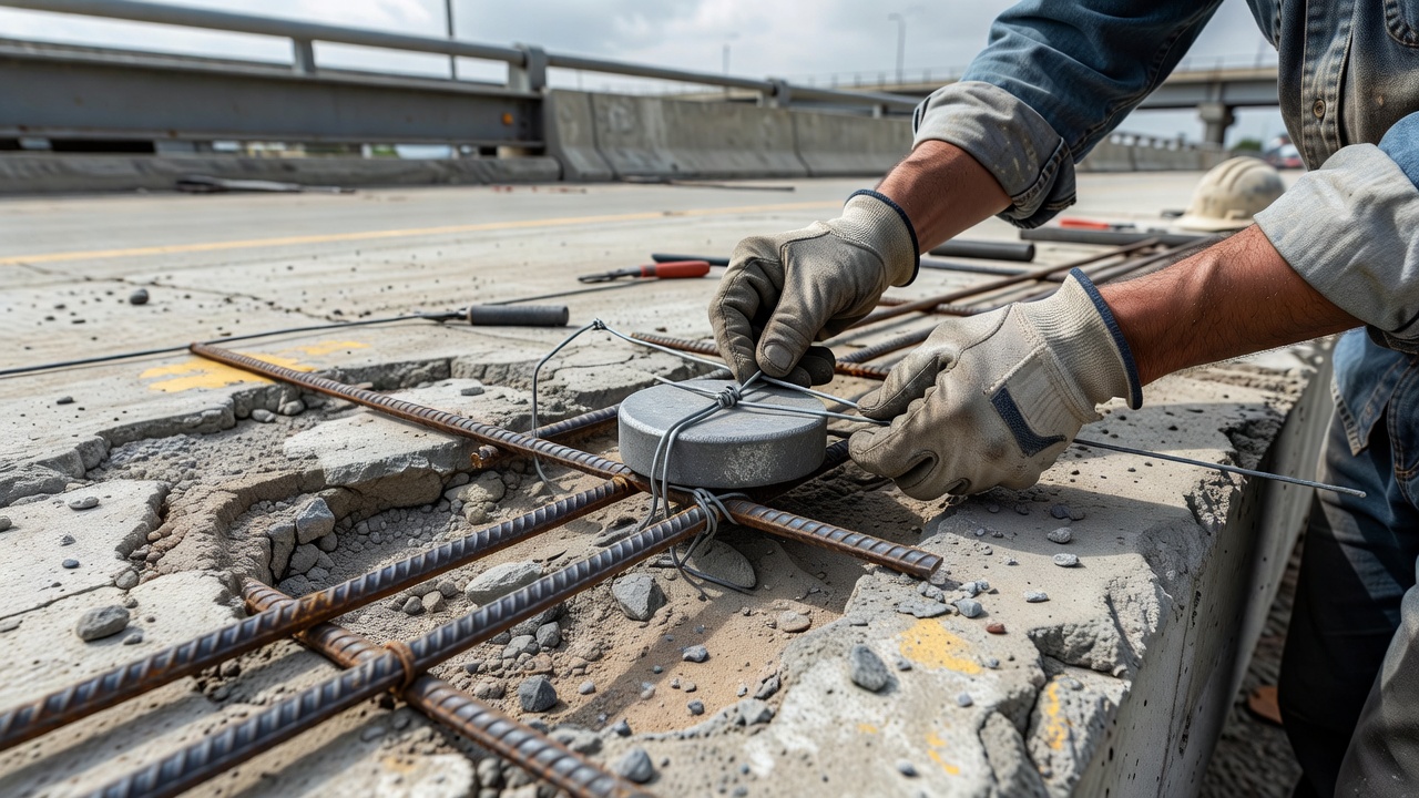
Discrete patch repair anodes — commonly shaped like hockey pucks — are installed around the perimeter of the concrete patch prior to placement of the repair material. The Galvashield® XP+ (formerly XP) contains 100 grams of encapsulated zinc and is 65 mm (2.6 inches) in diameter. The Sentinel-GL (Euclid Chemical) contains 40 grams of zinc and is a smaller V-notch block configuration. These anodes are pre-wetted in water for 10 to 30 minutes before installation to activate the internal electrolyte and are then wire-tied directly to the cleaned reinforcing bars. The anode must be positioned as close as practical to the patch perimeter — typically within 25 to 50 mm (1 to 2 inches) of the cut edge — to intercept the corrosion current at the halo zone.
The spacing of discrete patch repair anodes is determined by the anode manufacturer’s spacing tables or by the bridge owner’s standard specification. For the Galvashield XP+, a typical spacing is 12 to 24 inches (300 to 600 mm) around the patch perimeter, depending on the steel density ratio and the severity of the corrosive environment. NYSDOT classifies environments as highly corrosive (chloride content > approximately 5 lb/yd³ or 3 kg/m³) or slightly corrosive (chloride content < 5 lb/yd³). For highly corrosive conditions with moderate steel density (ratio 0.5 to 1.0), the maximum Sentinel-GL spacing is 18 inches (460 mm). For highly corrosive conditions with light steel density (< 0.5), the maximum spacing is 24 inches (610 mm).
The repair material used with galvanic anodes must have electrical resistivity less than 15,000 ohm-cm (15 kΩ·cm). Standard portland cement mortars and concretes (with w/c ratios of 0.40 to 0.50) typically have resistivities of 2,000 to 8,000 ohm-cm and are compatible. However, low-permeability repair materials containing microsilica (silica fume), high fly ash content, or polymer modifiers often have resistivities exceeding 20,000 ohm-cm and cannot be used directly with galvanic anodes without additional measures. If high-resistivity materials must be used, the anode should first be embedded in a normal-resistivity grout (standard cementitious mortar) that provides a conductive path to the surrounding concrete, as specified in ICRI Technical Guideline No. 03730 and ACI Repair Application Procedure RAP8.
Surface-applied galvanic anodes are installed on the external surface of existing concrete structures, eliminating the need for concrete removal. Three primary types are used: zinc mesh with hydrogel, zinc sheet with adhesive backing, and arc-sprayed (thermal-sprayed) zinc coatings.
Zinc mesh with hydrogel consists of an expanded zinc mesh (typically 0.5 to 1.0 mm wire diameter, 12 to 25 mm diamond opening) that is pressed against the prepared concrete surface and covered with a hydrogel — a water-absorbing polymer that maintains a conductive layer between the zinc and the concrete. The Galvanode® VP (Vector Corrosion Technologies) is a surface-applied system that uses a zinc mesh embedded in a humectant-activated hydrogel. The hydrogel attracts and retains moisture, maintaining ionic conductivity between the zinc and the concrete even in relatively dry environments. The system is covered with a cementitious overlay or protective coating. The zinc mesh provides a distributed anode area, reducing current density per unit area and extending service life.
Zinc sheet systems (e.g., Galvanode® ZincSheet) use a thin zinc sheet (0.5 to 1.0 mm thick) bonded to the concrete surface with a conductive adhesive. The zinc sheet is supplied in rolls and cut to size on site. Electrical connection to the reinforcing steel is made by welding a copper cable to the zinc sheet and connecting the cable to the steel reinforcement through drilled holes. The zinc sheet system is particularly suitable for underside protection of bridge decks, parking garage soffits, and pier caps where traffic wear is not a concern. The system has been applied successfully on over 50 structures in North America.
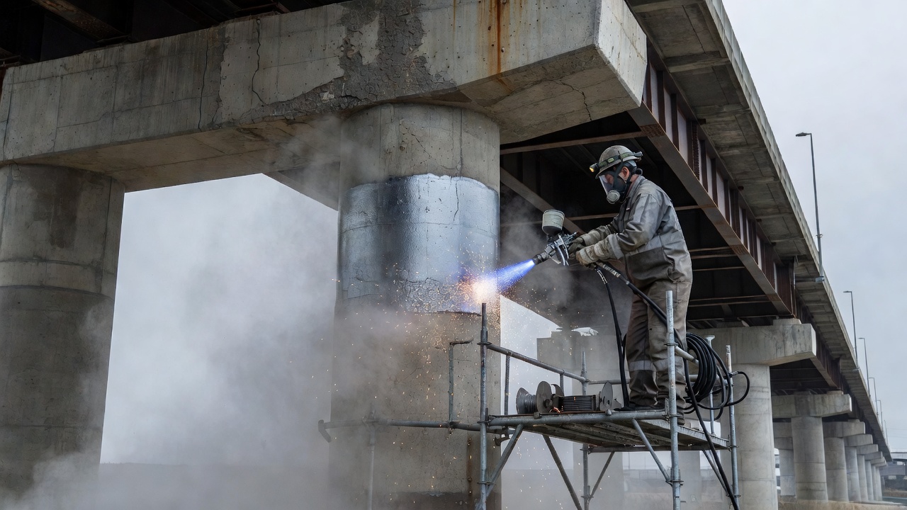
Arc-sprayed (thermal-sprayed) zinc (ASZ) — also known as metalizing — involves spraying molten zinc onto the concrete surface using an electric arc or flame spray gun. The Galvanode® ASZ+ system applies a thin coating (typically 0.3 to 0.5 mm thickness) of high-purity zinc to the prepared concrete surface. After installation, a humectant activator solution is applied to the zinc surface. Independent studies have shown that humectant activation enhances current output by up to 7 times over untreated zinc, depending on environmental conditions. The humectant attracts moisture, maintaining electrochemical activity and reducing the circuit resistance between the zinc coating and the steel. One of the key advantages of ASZ+ is the ability to reactivate the system by reapplying the humectant activator at intervals during the service life, extending the effective protection period to 15 to 20 years.
The bond strength of arc-sprayed zinc to concrete is a critical performance parameter. Studies on bridges including the Disraeli Freeway in Winnipeg, Manitoba and the Yaquina Bay Bridge in Oregon have shown that humectant-activated arc-sprayed zinc achieves bond strengths exceeding 2 MPa (290 psi) on properly prepared concrete surfaces. Surface preparation typically requires grit-blasting to achieve a near-white metal surface profile (SSPC-SP10 / NACE No. 2) with a minimum anchor profile of 75 to 100 μm (3 to 4 mils).
The service life of a galvanic anode is determined by the mass of sacrificial metal available and the rate at which it is consumed by the electrochemical reaction. The fundamental relationship is governed by Faraday’s law:
L = (m × E × η) / (I × 8760)
Where:
A typical discrete patch repair anode containing 100 grams of zinc (Galvashield XP+) delivering an average current of 1 mA (0.001 A) over its life: L = (0.100 × 820 × 0.90) / (0.001 × 8760) = 8.4 years. If the average current is 0.5 mA, the life extends to approximately 16.8 years. However, the current output is not constant — it decreases over time as zinc corrosion products accumulate on the anode surface, reducing the active surface area and increasing resistance. Field data from 23-year trials in the UK (Sergi, 2023) indicates that current output of alkali-activated galvanic anodes diminishes approximately exponentially with time.
Manufacturers provide guidance on consumption rate based on accelerated laboratory testing (ASTM G97 — Standard Test Method for Laboratory Evaluation of Magnesium Sacrificial Anode Test Specimens) and field validation. For discrete embedded zinc anodes in bridge decks, the consumption rate is typically 0.5 to 2 mA per anode initially, declining to 0.1 to 0.5 mA after 5 to 10 years. The total zinc mass is the primary design variable — larger anodes (e.g., 135-gram Galvashield CC 135) provide longer service life than standard 65-gram units, but at increased cost per anode.
| Anode Type | Zinc Mass | Typical Initial Current | Service Life (Projected) |
|---|---|---|---|
| Sentinel-GL (discrete patch) | 40 g | 0.3–0.8 mA | 5–10 years |
| Galvashield XP+ (discrete patch) | 100 g | 0.5–2 mA | 7–15 years |
| Galvashield CC 135 (embedded grid) | 135 g | 0.8–3 mA | 10–20 years |
| Arc-sprayed zinc (ASZ+) 0.3 mm | ~220 g/m² | 1–5 mA/m² | 10–15 years |
| Arc-sprayed zinc (ASZ+) 0.5 mm | ~360 g/m² | 1–5 mA/m² | 15–20 years |
The design of a galvanic anode cathodic protection system requires determination of the number, type, and spacing of anodes to deliver sufficient current to polarize the reinforcing steel to the protection criterion over the design service life. The step-by-step design process, as documented in NYSDOT Bridge Maintenance guidelines and NACE SP0290, follows:
Step 1 — Condition Assessment: Conduct a condition survey including delamination sounding (chain drag or hammer sounding), half-cell potential mapping (ASTM C876), chloride content profiling (ASTM C1152), concrete cover measurement (ASTM C876 cover meter), and concrete resistivity measurement (Wenner 4-probe method per ASTM C1876).
Step 2 — Steel Density Ratio Calculation: Calculate the steel density ratio (SDR) using the formula:
SDR = (π × d₁ / s₁) + (π × d₂ / s₂)
Where d₁ and d₂ are the bar diameters in the longitudinal and transverse directions, and s₁ and s₂ are the bar spacings. For a bridge deck with #5 bars (0.625 in diameter) at 8-inch spacing in both directions: SDR = (π × 0.625 / 8) + (π × 0.625 / 8) = 0.245 + 0.245 = 0.490.
Step 3 — Environment Classification: Classify the environment as highly corrosive (chloride content > 5 lb/yd³, active corrosion visible, spalling/delamination present) or slightly corrosive (chloride content < 5 lb/yd³, minimal corrosion damage). The NYSDOT tables use different spacing categories for each.
Step 4 — Anode Selection and Spacing: Using the SDR and environment classification, select the anode spacing from manufacturer tables. For Sentinel-GL: SDR < 0.5 in highly corrosive environment → maximum spacing 24 inches; SDR 0.5 to 1.0 in highly corrosive environment → maximum spacing 18 inches; SDR > 1.0 in highly corrosive environment → maximum spacing 12 inches.
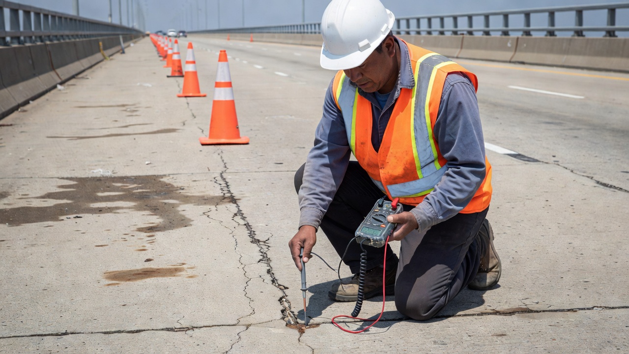
Step 5 — Connection Verification: All reinforcing steel in the protected zone must be electrically continuous. Lapped bars, tied wire connections, and welded connections provide continuity. If discontinuous steel is found (e.g., separate mats, epoxy-coated bars with damaged coating), continuity must be re-established by welding a jumper wire of minimum 12-gauge (AWG) copper wire or by welding a #4 rebar section across the discontinuity. Continuity is verified with a multimeter — resistance between any two points in the reinforcement should be less than 1 ohm.
For prestressed and post-tensioned concrete, special consideration is required. The electrical connection between the anode and the prestressing strands must be designed to avoid excessive current that could cause hydrogen embrittlement. The current density delivered to high-strength steel should be limited to less than 1 mA per strand to mitigate this risk.
Electrical continuity is the prerequisite for galvanic anode function. Without a continuous metallic path, the protective current cannot circulate from the anode through the concrete to the steel and back through the wiring to the anode. Continuity testing follows procedures in NACE Standard TM0108 (Testing of Cathodic Protection Systems) and ASTM G96.
The continuity test is performed using a digital multimeter (accuracy ±0.1 mV, minimum 10 MΩ input impedance). The procedure:
For surface-applied systems such as zinc mesh or arc-sprayed zinc, continuity is verified by measuring the resistance from the anode surface at multiple locations to the reinforcing steel. A water-soaked sponge is placed between the half-cell and the anode surface to ensure ionic contact. The measured resistance should be less than 100 ohms for surface-applied zinc mesh systems and less than 500 ohms for arc-sprayed coatings.
Regular inspection ensures that galvanic anode systems continue to provide effective corrosion protection. The inspection program follows the requirements of NACE SP0290 (Impressed Current Cathodic Protection of Reinforcing Steel in Atmospherically Exposed Concrete Structures — applicable by analogy to galvanic systems), ASTM C876 (Half-Cell Potentials of Uncoated Reinforcing Steel in Concrete), and ICAO Annex 14 for airfield applications.
Half-cell potential mapping is performed annually using a CSE reference electrode in accordance with ASTM C876. Potential measurements are taken on a grid (typically 1 to 5 feet / 0.3 to 1.5 m spacing). Interpretive criteria per ASTM C876:
For galvanic CP evaluation, the 100 mV polarization decay test is the standard performance criterion. The test involves interrupting the galvanic circuit (disconnecting the anode lead wire) and measuring the potential of the reinforcing steel at intervals over 4 to 24 hours. A potential decay of 100 mV or more from the instant-off potential indicates effective cathodic protection per NACE RP0290.
Anode consumption inspection for surface-applied systems is conducted every 2 to 5 years. For arc-sprayed zinc, the coating thickness is measured using an electromagnetic thickness gauge (ASTM D7091). A 0.3 mm nominal coating will show progressive thinning. When the remaining thickness drops below 0.1 mm, the system requires reactivation or replacement. For zinc mesh systems, visual inspection for corrosion product accumulation and delamination is performed. The hydrogel activator is assessed for moisture content — if the hydrogel has dried out, the humectant activator is reapplied.
Discrete embedded anodes cannot be directly inspected for consumption without destructive removal. Instead, indirect assessment is performed by measuring:
Periodic inspection frequency recommended by FHWA and NACE:
Galvanic anode cathodic protection has extensive application in both airport pavement infrastructure and highway/rail bridge structures, where corrosion of reinforcing steel is the primary deterioration mechanism limiting service life.
Airport concrete pavements are subject to corrosion from deicing chemicals — primarily liquid potassium acetate, sodium formate, and urea-based formulations — applied to runways, taxiways, and apron areas. These chemicals penetrate the concrete and depress the pH, breaking down the passive film on steel. The FAA Advisory Circular AC 150/5320-6G (Airport Pavement Design and Evaluation) and AC 150/5370-10H (Standards for Specifying Construction of Airports) recognize cathodic protection as a corrosion control strategy. FAA Engineering Briefs specify that galvanic anodes can be installed at joints and around dowel bars during pavement reconstruction.
Discrete galvanic anodes are installed at construction joints and expansion joints in new airfield concrete pavements. The anodes protect the dowel bars and tie bars, which are the first reinforcing elements to corrode because of their position at the joint interface where deicing chemicals ingress. Anodes are placed at 12 to 24 inch (300 to 600 mm) spacing on both sides of the joint, tied to the dowel bar cage prior to concrete placement. The Denver International Airport and Seattle-Tacoma International Airport have used galvanic anode protection in selected apron areas.
ICAO Annex 14 — Aerodromes, Volume I, Chapter 10 (Section 10.4 Pavement Maintenance) requires that airfield pavement surfaces be maintained to prevent foreign object debris (FOD) caused by concrete spalling from corroded reinforcing steel. Galvanic anode CP is a recognized preventive measure under the ICAO Aerodrome Certification Framework.
Bridge applications are the most widespread use of galvanic anodes. North America has over 350 structures protected by cathodic protection (both galvanic and impressed current), according to SHRP-S-337 (Strategic Highway Research Program). The Missouri DOT leads with over 100 CP installations, followed by Ontario Ministry of Transportation with nearly 50. A survey cited in SHRP-S-337 indicated that 90% of installations were operating satisfactorily as designed.
Typical bridge applications:
The life-cycle cost benefit of galvanic anode protection is substantial. Research by Krishnan et al. (2021, Journal of Building Engineering) demonstrated that repair using galvanic anodes can achieve approximately 90% life cycle cost savings compared to conventional patch-and-patch repair strategies, primarily by eliminating the halo effect and preventing recurring repairs. The NYSDOT Bridge Maintenance Guidelines recommend galvanic anodes as a cost-effective strategy when a medium-term repair (5 to 10 years) is desired, noting that the incremental cost of adding anodes to a standard concrete patch repair is approximately 15 to 25% of the base repair cost.
| Structure Type | Anode System | Service Life Extension | Cost per m² (installed) |
|---|---|---|---|
| Bridge deck patch | Discrete XP+ (100 g) | 7–15 years | $25–$50/m² incremental |
| Bridge deck overlay | Zinc mesh + hydrogel | 10–15 years | $40–$80/m² |
| Marine substructure | Arc-sprayed zinc ASZ+ | 10–20 years | $60–$120/m² |
| Airport pavement joint | Discrete Sentinel-GL | 5–10 years | $30–$60/m² |
| Parking garage soffit | Zinc sheet bonded | 10–15 years | $50–$90/m² |
Get expert guidance on galvanic anode cathodic protection systems for bridges, airport pavements, and marine concrete structures. Our specialists assess corrosion risk and design long-lasting protection solutions.
Cathodic protection is an electrochemical corrosion mitigation technique that prevents reinforcement corrosion in concrete structures by making the steel the ca...
Impressed Current Cathodic Protection (ICCP) applies a small DC current from an external power source through inert anodes to reinforcing steel, forcing the ste...
Corrosion protection for reinforced concrete encompasses multiple strategies: adequate concrete cover, low-permeability concrete with supplementary cementitious...