Geotextile
Geotextiles are permeable synthetic fabrics used in pavement and geotechnical applications for separation (preventing subgrade-aggregate mixing), filtration (co...
34 min read
Pavement
Construction
+4
Geogrids are high-strength polymer grids used to reinforce soil, aggregate, and asphalt layers, improving load distribution, reducing rutting, and extending pavement life through interlock with aggregate particles. Covers geogrid types, reinforcement mechanisms, placement, and inspection of pavement sections with geogrid history.
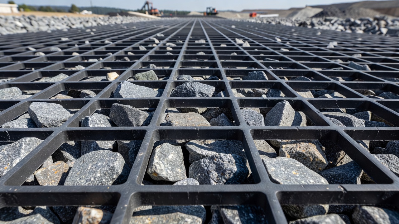
A geogrid is a geosynthetic material consisting of connected parallel sets of tensile ribs with apertures (open spaces) of sufficient size to allow strike-through of surrounding soil, stone, or other geotechnical material. Unlike geotextile, which is a continuous fabric used primarily for separation and filtration, geogrid is engineered specifically for soil reinforcement — adding tensile strength to a soil mass that inherently cannot resist tension on its own. The apertures in a geogrid range typically from 25 mm to 150 mm in dimension, depending on the type and manufacturer, and the open area percentage generally exceeds 50% of the total surface, ensuring adequate space for aggregate interlock.
Geogrids were invented by Dr. Frank Brian Mercer, who patented the Netlon process of extruding molten plastic into grids in the 1950s. Mercer saw the potential for civil engineering applications and developed the revolutionary Tensar process in 1978. This process stretched the polymer grid to align the long-chain molecules in the ribs and through the junctions, dramatically increasing strength and durability. The resulting material became known as Tensar geogrid. The first field trial took place in 1980 at Newmarket Silkstone Colliery, Yorkshire, where uniaxial geogrid reinforced minestone waste to stabilize embankments and biaxial geogrid stabilized aggregate beneath a railway. Performance exceeded expectations — no discernible settlement occurred in three years despite up to 300 tonnes of waste passing over the railway every hour.
The invention earned Mercer the MacRobert Award from the Royal Academy of Engineering in 1984. In 2013, Tensar geogrid was named one of the British inventions of the 20th century alongside Alan Turing’s Universal Machine. Today, geogrids are manufactured globally by numerous companies including Tensar, Strata, Maccaferri, HUESKER, TenCate, and GSE, with applications spanning roads, railways, airports, retaining walls, slopes, landfills, and foundations.
Geogrid materials fall into four polymer categories: HDPE (high-density polyethylene), which is standard for uniaxial geogrids and offers excellent long-term tensile strength, UV resistance, and chemical stability; polypropylene (PP), standard for biaxial and triaxial geogrids, providing good strength, flexibility, and cost-effectiveness; polyester (PET), used for high-strength woven geogrids, offering the highest tensile strength per unit weight and excellent creep resistance; and fiberglass, coated with bitumen for asphalt reinforcement in road overlays, delivering very high modulus at low strain for effective crack control.
Geogrids are classified into three primary types based on their aperture geometry and strength orientation: uniaxial, biaxial, and triaxial. A fourth category, geogrid-geotextile composites, combines reinforcement with filtration-separation functions for challenging subgrade conditions.
Uniaxial geogrids have high tensile strength in one direction only — the machine direction (MD), which runs along the length of the roll. The ribs are oriented lengthwise with minimal cross-ribs, and the polymer molecules are aligned during manufacturing through a uniaxial stretching process. This orientation maximizes tensile modulus and strength in the primary load direction.
| Property | Uniaxial Geogrid |
|---|---|
| Primary reinforcement direction | Machine direction (MD) only |
| Aperture shape | Rectangular, elongated |
| Tensile strength range | 40 kN/m to 400+ kN/m (MD) |
| Polymer type | Typically HDPE |
| Typical applications | Retaining walls, steep slopes, embankments, bridge abutments, landfill side slopes |
Uniaxial geogrids are best suited for mechanically stabilized earth (MSE) walls, segmental block retaining walls, and steep reinforced slopes where the primary load direction is predictable and consistent. In retaining wall applications, horizontal layers of geogrid extend back into the retained soil mass. The outward pressure from the retained soil creates tension in the geogrid, which the uniaxial orientation resists through friction and interlock with the soil. Tensile strengths for uniaxial geogrids can exceed 400 kN/m in a single layer, enabling construction of reinforced soil structures up to 60 meters in height.
Biaxial geogrids provide balanced tensile strength in two perpendicular directions — machine direction (MD) and cross-machine direction (CMD). The apertures are typically square or rectangular, with ribs running orthogonally. Manufacturing involves punching holes in a sheet of HDPE or polypropylene and then stretching the sheet in both directions sequentially, resulting in balanced strength properties.
| Property | Biaxial Geogrid |
|---|---|
| Primary reinforcement direction | MD and CMD (balanced) |
| Aperture shape | Square or rectangular |
| Tensile strength range | 20 kN/m to 50 kN/m in each direction |
| Polymer type | Typically polypropylene or HDPE |
| Typical applications | Road base reinforcement, parking lots, railway ballast, working platforms, subgrade stabilization |
Biaxial geogrids dominate road construction because traffic loads create stresses in multiple directions simultaneously — longitudinal along the road, transverse across it, and at various intermediate angles. The balanced strength in both primary directions matches the actual load distribution in a pavement structure. Road base reinforcement with biaxial geogrid typically reduces aggregate thickness requirements by 30% to 50% compared to unreinforced sections, while extending pavement life by a factor of 2 to 5 depending on subgrade conditions.
Triaxial geogrids (marketed as TriAx by Tensar) represent a next-generation enhancement to biaxial geogrids. They feature triangular apertures with ribs oriented in three equilateral directions (60-degree spacing), forming a hexagonal pattern. This geometry provides enhanced in-plane stiffness — the resistance to deformation within the plane of the geogrid — which improves stress transfer from the aggregate to the geogrid under traffic loading.
| Property | Triaxial Geogrid |
|---|---|
| Primary reinforcement direction | Three equilateral directions (60°) |
| Aperture shape | Triangular (hexagonal pattern) |
| Tensile strength range | 20 kN/m to 40 kN/m (radial) |
| Polymer type | Polypropylene |
| Typical applications | Paved and unpaved roads, airport pavements, heavy-duty surfaces |
Triaxial geogrids were introduced in 2007 and have undergone extensive full-scale testing, including at the US Army Corps of Engineers and the University of Nottingham. The triangular aperture geometry provides better aggregate confinement in all directions compared to biaxial grids, which is particularly beneficial for unbound aggregate layers where particle movement under load is the primary failure mechanism. Triaxial geogrids have been calibrated within common pavement design methodologies for both paved and unpaved applications.
These composites consist of a geogrid layer heat-bonded or ultrasonically welded to a geotextile fabric. The combination provides reinforcement from the geogrid and filtration/separation from the geotextile in a single product. They are ideal for very soft subgrade conditions where fines migration from the subgrade into the aggregate base must be prevented, and where the geogrid must provide both tensile reinforcement and the geotextile must satisfy filtration retention criteria.
The US Army Corps of Engineers, in Engineering Technical Letter (ETL) 1110-1-189, defined three primary mechanisms for how geogrids reinforce pavement and soil structures. Understanding these mechanisms is essential for proper design, specification, and quality control during construction and subsequent pavement inspections.
Lateral restraint is the primary reinforcement mechanism and the most significant in terms of pavement performance improvement. When aggregate is placed over geogrid and compacted, the aggregate particles penetrate through the apertures and lock around the ribs. This mechanical interlock confines the aggregate particles within the plane of the geogrid, preventing them from moving laterally under traffic loads.
The mechanism works as follows: under a wheel load, the aggregate layer experiences horizontal tensile stresses at the base of the layer. In an unreinforced section, these stresses cause aggregate particles to spread laterally, resulting in rutting and layer thinning. In a geogrid-reinforced section, the interlocked aggregate-geogrid composite resists these tensile stresses because the geogrid ribs carry the tension. This confinement increases the stiffness of the stabilized aggregate layer by 2 to 5 times compared to unstabilized aggregate, depending on the geogrid type and aggregate angularity.
The lateral restraint mechanism is most effective when:
Improved bearing capacity, also known as the snowshoe effect, becomes the dominant mechanism on soft subgrades (California Bearing Ratio, CBR, less than 3). Just as a snowshoe distributes a person’s weight over soft snow, the stiff composite layer of geogrid-reinforced aggregate distributes traffic loads over a wider area on the subgrade surface.
The mechanism works because the geogrid-reinforced base layer behaves as a stiff slab rather than as separate aggregate particles. This slab action spreads the vertical load over a larger subgrade area, reducing the vertical stress on the subgrade to below its bearing capacity. The improved bearing capacity allows construction traffic to operate on subgrades that would otherwise be impassable, and it significantly reduces the thickness of aggregate required for the final pavement section.
Field studies have demonstrated that geogrid reinforcement can increase the effective bearing capacity of soft subgrades by 1.5 to 3 times, enabling aggregate savings of 30% to 50% in pavement base thickness. This mechanism is particularly important for airport pavements where aircraft loads are significantly higher than highway loads.
The tension membrane effect occurs when the geogrid develops tensile stresses under vertical load, providing additional support like a taut membrane. This mechanism becomes active only after some vertical deformation (rutting) has occurred — typically 50 mm to 100 mm in unpaved applications. As the subgrade deforms under load, the geogrid is forced into tension, generating upward vertical forces that help support the applied load.
In paved applications, the tension membrane effect is less significant because allowable rut depths are much smaller (typically 6 mm to 12 mm for highways, 3 mm to 6 mm for airport runways). However, in unpaved roads and temporary working platforms, this mechanism can provide substantial additional bearing capacity.
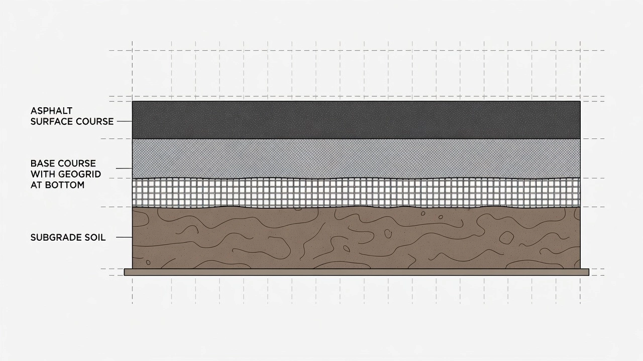
The most common application of geogrid in pavement engineering is base course reinforcement, where the geogrid is placed at the interface between the prepared subgrade and the granular base layer. The purpose is threefold: to reduce the required thickness of aggregate, to extend the pavement’s service life, and to improve construction access over weak subgrades.
The geogrid is typically placed directly on the prepared subgrade before the base course is placed and compacted. In some pavement optimization designs, geogrid may be placed at mid-depth within the base course to provide additional confinement within the aggregate mass. The optimal placement depends on the pavement structure, subgrade strength, and anticipated loads.
For subgrade stabilization (CBR less than 3), the geogrid is always placed at the subgrade-base interface to maximize the bearing capacity improvement. For base reinforcement (CBR greater than 3), geogrid may be placed at the interface or within the base, depending on the design objectives.
The use of geogrid in base reinforcement allows significant reduction in aggregate thickness. Design methods such as the Giroud-Han method, the Tensar pavement design methodology, and the AASHTO empirical method with geogrid adjustment factors provide rational approaches for determining the reinforced section thickness. Typical thickness reduction ratios range from:
| Subgrade CBR | Unreinforced Base Thickness | Reinforced Base Thickness | Reduction |
|---|---|---|---|
| 1% | 600 mm | 400 mm | 33% |
| 2% | 450 mm | 300 mm | 33% |
| 3% | 350 mm | 250 mm | 29% |
| 5% | 250 mm | 200 mm | 20% |
| 10% | 200 mm | 175 mm | 12% |
Geogrid-reinforced base sections consistently outperform unreinforced sections in accelerated pavement testing and long-term field monitoring. Key performance indicators include:
Geogrid is used in asphalt overlays and new asphalt pavements to control reflective cracking — one of the largest contributors to pavement deterioration. Reflective cracking occurs when cracks in an existing pavement layer propagate through an overlay due to thermal movements and traffic loads. Without reinforcement, conventional rehabilitation with an asphalt overlay provides limited additional service life — approximately one year per inch (25 mm) of overlay thickness.
Asphalt reinforcement geogrids are typically made of fiberglass or polyester yarns, coated with modified bitumen for chemical resistance and bonding with the asphalt layers. Products include:
The geogrid is placed between the existing pavement and the overlay, or within the new asphalt layer at the depth where tensile stresses are highest. Installation steps include:
Field studies and accelerated pavement testing have demonstrated that asphalt reinforcement with geogrid:
Geogrids are extensively used in mechanically stabilized earth (MSE) structures, including retaining walls, steep slopes, embankments, and bridge abutments. In these applications, the geogrid provides tensile reinforcement that allows soil to stand at steeper angles than its natural angle of repose.
In segmental retaining walls (SRW) and precast concrete panel walls, uniaxial geogrid layers are placed horizontally, extending back from the wall face into the retained soil mass. The geogrid layers are spaced vertically according to the design, typically 300 mm to 600 mm apart. The length of the geogrid layers ranges from 50% to 80% of the wall height, depending on the wall type, soil properties, and loading conditions.
The reinforcement mechanism in retaining walls involves:
These mechanisms generate enough pullout resistance to hold the wall facing in place against the active earth pressure of the retained soil.
For steep slopes (slopes steeper than 1H:1V), geogrid layers are placed within the embankment fill during construction. The geogrid wraps around the slope face or terminates at the face within a protective cover layer. This reinforcement allows slopes to be constructed at angles of 45° to near-vertical while maintaining long-term stability.
Design of geogrid-reinforced slopes follows limit equilibrium methods (Bishop, Janbu, Spencer) and considers:
Proper design and specification of geogrid reinforcement requires consideration of material properties, soil conditions, loading, and construction quality. The following properties are critical for specification:
| Property | Test Method | Description |
|---|---|---|
| Tensile strength | ASTM D6637, ISO 10319 | Ultimate tensile strength per unit width (kN/m) |
| Tensile strength at 2% strain | ASTM D6637 | Critical for serviceability limit state design |
| Tensile strength at 5% strain | ASTM D6637 | Used in deformation-based design |
| Junction efficiency | ASTM D7737 | Ratio of junction strength to rib strength |
| In-plane stiffness | Tensar proprietary test (for triaxial) | Modulus of the geogrid at low strain |
| Creep reduction factor | ASTM D5262, ISO 13431 | Long-term strength reduction due to sustained loading |
| Installation damage factor | ASTM D5818, ISO 10722 | Strength reduction due to construction handling |
Several design methods are available for geogrid-reinforced pavements:
Giroud-Han method: The most widely accepted analytical method for geogrid-reinforced unpaved roads. Uses a bearing capacity approach with a modulus improvement factor (J) that accounts for geogrid type and properties.
AASHTO mechanistic-empirical method: Uses elastic layer theory with an increased modulus for the geogrid-reinforced base layer. The reinforced base modulus is typically 1.5 to 3 times the unreinforced base modulus.
Tensar pavement design methodology: Proprietary method calibrated from extensive full-scale testing. Incorporates the specific properties of TriAx geogrid through the TX Module — a structural layer coefficient specific to the geogrid-aggregate composite.
US Army Corps of Engineers ETL 1110-1-189: Provides guidance for design of geogrid-reinforced flexible pavements for military airfields and roads.
A complete geogrid specification should include:
Proper geogrid installation is as important as proper design. The construction sequence affects both short-term performance and long-term durability.

The subgrade or surface receiving the geogrid must be cleared, grubbed, and graded to the design elevation. For pavement applications, the subgrade should be compacted to project specifications and proof-rolled to identify soft spots that may require additional treatment. For very soft subgrades (CBR less than 0.5), minimal disturbance is recommended — root mats may be left in place, and stumps should be cut as close to the ground surface as practical.
Geogrid rolls are positioned at the start of the coverage area, the roll bands are cut, and the material is manually unrolled over the prepared surface. The long axis of the roll is typically parallel to channelized traffic patterns. For pavement applications, the geogrid is rolled out with light tension to remove wrinkles and laid flat against the subgrade.
Adjacent geogrid rolls must be overlapped to ensure continuity of reinforcement. Overlap width depends on subgrade strength:
| Subgrade CBR | Minimum Overlap |
|---|---|
| Less than 1 | 3 ft (0.9 m) |
| 1 to 2 | 2 to 3 ft (0.6 to 0.9 m) |
| 2 to 4 | 1 to 2 ft (0.3 to 0.6 m) |
| Greater than 4 | 1 ft (0.3 m) |
Geogrids should be shingled in the direction of fill placement — each subsequent roll placed on top of the previous roll’s edge — to prevent advancing fill from peeling the geogrid at overlaps. Placement should proceed from the far end toward the near end relative to fill delivery.
The initial lift of aggregate fill over geogrid must be a minimum of 6 inches (150 mm) for standard conditions, and thicker for very soft subgrades to prevent bearing failure. Aggregate fill may be dumped directly onto the geogrid over competent subgrades (CBR greater than 4). Over softer subgrades, trucks should back up and dump onto previously placed fill to prevent overstressing the geogrid.
Do not operate tracked equipment directly on geogrid. At least 6 inches of aggregate fill must be spread between the geogrid and tracked vehicles. Rubber-tired equipment may operate directly on geogrid only over competent subgrades with limited construction traffic. Compaction follows standard procedures, using vibratory or static rollers as appropriate for the subgrade conditions.
Geogrid should be anchored at the beginning of the roll using sod staples, pins with washers, or small piles of aggregate. The roll is then unrolled and pulled taut to remove laydown slack. Proper tensioning prevents waving — the accumulation of loose geogrid ahead of advancing fill — which can cause the geogrid to fold into the aggregate layer and become ineffective.
The performance of geogrid-reinforced pavements is measured through rut depth progression, fatigue life, crack initiation and propagation, and structural condition over time. Extensive field monitoring and accelerated pavement testing have established the performance benefits.
Geogrid reinforcement reduces permanent deformation (rutting) in both the aggregate base and the subgrade. The lateral restraint mechanism confines aggregate particles, preventing the lateral movement that causes rutting. The improved bearing capacity mechanism reduces subgrade stress, limiting subgrade rutting. Typical rutting reductions are 30% to 60% depending on subgrade strength, traffic, and geogrid type.
The service life extension provided by geogrid reinforcement is measured by the traffic benefit ratio (TBR) — the ratio of the number of load repetitions to failure in a reinforced section compared to an unreinforced section of the same thickness. TBR values range from:
| Application | Typical TBR |
|---|---|
| Thin asphalt pavements over weak subgrade | 3 to 10 |
| Thin asphalt pavements over moderate subgrade | 2 to 5 |
| Unpaved roads over weak subgrade | 2 to 8 |
| Asphalt overlays for reflective cracking | 2 to 4 |
| Heavy-duty pavements and airports | 1.5 to 3 |
The base course reduction (BCR) expresses the percentage reduction in aggregate thickness achievable with geogrid reinforcement for a given traffic level and subgrade strength. BCR values of 20% to 50% are common, with higher savings on weaker subgrades. This reduction translates directly into cost savings, reduced carbon footprint from aggregate transportation and processing, and faster construction.
Case studies of geogrid-reinforced pavements with service lives exceeding 20 years demonstrate that the reinforcement benefits persist over the pavement’s design life. A notable example is the N. Causeway Blvd. in Metairie, Louisiana, where GlasGrid asphalt reinforcement kept the road relatively crack-free for over 17 years. The Shreveport Downtown Airport taxiway in Louisiana remained relatively crack-free for 17+ years after installation of geogrid-reinforced overlay.
Inspection of geogrid-reinforced pavements during construction and in service requires attention to both the geogrid itself and the pavement layers it reinforces. Understanding how geogrid influences pavement behavior helps in interpreting inspection results.
During construction, inspection should verify:
For in-service pavement inspection, the presence of geogrid affects how distresses develop and should be considered:
Rutting: In geogrid-reinforced sections, rutting develops more slowly and typically occurs in the surface layer rather than the base. Deep rutting (greater than 25 mm) may indicate geogrid failure or inadequate initial design.
Cracking: In asphalt-reinforced sections, cracking patterns may differ from unreinforced sections. Reflective cracks are typically narrower and more tightly closed. Map cracking or alligator cracking that appears in asphalt overlay over geogrid may indicate debonding at the geogrid interface rather than structural failure.
Delamination: A hollow sound when tapping the asphalt surface (or visible stripping in cores) may indicate delamination at the geogrid interface, which occurs when the tack coat was insufficient or the overlay was placed before the tack coat cured.
Core samples: Extracted cores should show the geogrid positioned at the specified depth, with aggregate or asphalt penetrating through the apertures. The geogrid should be fully encapsulated and bonded with the surrounding material.
Falling Weight Deflectometer (FWD) testing of geogrid-reinforced pavements typically shows:
Ground Penetrating Radar (GPR) can identify the geogrid layer position if the grid has sufficient dielectric contrast with the surrounding material. However, thin polymer geogrids (2 mm to 5 mm thick) may be below the resolution limit of standard GPR equipment operating at 1 GHz or 2 GHz frequencies.
Geogrids are increasingly specified in airport pavement construction under the guidance of FAA Advisory Circular 150/5320-6G (Airport Pavement Design and Evaluation) and ICAO Aerodrome Design Manual Part 3 (Pavements).
FAA AC 150/5320-6G (Chapter 2, Section 2.4) provides guidance on subgrade stabilization for airport pavements. The AC recognizes that stabilization may be required when:
While the FAA AC primarily addresses cement stabilization and lime stabilization, geogrid reinforcement is increasingly specified as an alternative or complement to chemical stabilization for subgrade improvement. Geogrid provides immediate reinforcement without curing time, allowing construction to proceed more rapidly than with cement stabilization methods.
For airport pavements, geogrid design must consider:
Shreveport Downtown Airport (DTN), Louisiana: The taxiway pavement was reinforced with fiberglass geogrid (GlasGrid) asphalt reinforcement in the overlay. After 17 years of service, the pavement remained relatively crack-free, demonstrating the long-term effectiveness of geogrid in airport applications. This application is documented in Tensar’s case study library and referenced in Tensar’s asphalt reinforcement success stories.
Fujairah Freeway, UAE: While primarily a highway project, this application demonstrates the scale of geogrid use in heavy civil engineering — Tensar wall systems used geogrid to build up to 60-meter-high reinforced soil retaining walls connecting Dubai to Al Fujairah.
Geogrids used in airport pavement reinforcement should be specified with:
Geogrid is a high-strength polymeric grid designed for soil and pavement reinforcement through mechanical interlock with aggregate particles. Available in uniaxial, biaxial, and triaxial configurations, each suited to specific applications. The three reinforcement mechanisms — lateral restraint, improved bearing capacity, and tension membrane effect — work together to reduce rutting, extend pavement life, and reduce aggregate thickness requirements by 20% to 50%. Proper installation including correct overlap, tensioning, and fill placement is essential for achieving the specified performance. In airport applications, geogrid provides cost-effective subgrade stabilization, base course reinforcement, and asphalt overlay crack control under the high loads characteristic of aircraft traffic.
Enhance your airport pavement inspection and evaluation capabilities with TarmacView's advanced data collection and analysis platform. Understand how reinforcement materials like geogrids affect pavement performance.
Geotextiles are permeable synthetic fabrics used in pavement and geotechnical applications for separation (preventing subgrade-aggregate mixing), filtration (co...
Cementitious grouting uses fluid cement-based mixtures poured or pumped to fill cracks, voids, or spaces in concrete — including tendon duct grouting, crack inj...
Soil nailing is an in-situ ground reinforcement technique where closely spaced steel bars are grouted into a soil slope or excavation face as construction proce...