Geogrid
Geogrids are high-strength polymer grids used to reinforce soil, aggregate, and asphalt layers, improving load distribution, reducing rutting, and extending pav...
22 min read
Pavement
Construction
+3
Geotextiles are permeable synthetic fabrics used in pavement and geotechnical applications for separation (preventing subgrade-aggregate mixing), filtration (controlled water flow with soil retention), drainage (in-plane water conveyance), and reinforcement (tensile strengthening of soil mass). Covers geotextile types, AASHTO M288 specifications, polymer chemistry, functions, airport pavement standards, and inspection of exposed or failed geotextile in deteriorated pavements.
A geotextile is defined by ASTM D4439 as a permeable geosynthetic comprised solely of textile materials. Per ISO 10318-1:2015, a geotextile is a planar, permeable, polymeric material used in contact with soil or other materials in geotechnical and civil engineering applications. Geotextiles are manufactured from synthetic polymers — primarily polypropylene (PP) and polyester (PET) — chosen for their predictable engineering properties, chemical resistance, and long-term durability in soil environments. The global geotextile market exceeds 3 billion square meters annually, driven by infrastructure development in transportation, mining, waste containment, water management, and coastal protection sectors.
The distinguishing characteristic of a geotextile versus other geosynthetics is permeability — it is designed to allow water to pass through its structure while retaining soil particles. This dual capability of managing both mechanical (soil) and hydraulic (water) behavior makes geotextiles fundamentally different from geogrids (open-grid structures for reinforcement only) and geomembranes (impermeable barriers). Geotextiles occupy a unique position in the geosynthetic family as multi-functional materials capable of performing separation, filtration, drainage, reinforcement, and protection — often more than one function simultaneously within a single installation.
The engineering behavior of geotextiles is governed by three groups of properties: physical properties (mass per unit area, thickness, specific gravity), mechanical properties (tensile strength, tear resistance, puncture resistance, burst strength, interface friction angle, creep behavior), and hydraulic properties (permittivity or water flow rate, apparent opening size or AOS, transmissivity or in-plane flow capacity, porosity, clogging resistance). Specifying a geotextile for a particular application requires matching these properties to the project’s soil conditions, loading, groundwater regime, and construction methodology.
The modern geotextile industry traces its origins to the 1950s when R.J. Barrett at the US Army Corps of Engineers used woven cotton fabric to stabilize beach sand under concrete revetments. The first synthetic geotextile applications emerged in the 1960s in Europe and Japan using woven polypropylene tapes. The landmark publication of Giroud (1981) established the first comprehensive engineering design methodology for geotextiles used in unpaved roads. The US Federal Highway Administration published FHWA-HI-95-038 (Geosynthetic Design and Construction Guidelines, Holtz, Christopher, and Berg, 1997) which remains the reference standard for transportation applications. AASHTO M288 codified material specifications in a nationally adopted format, evolving from the earlier Task Force 25 guidelines through current M288-21 edition.
The performance and service life of a geotextile depend fundamentally on the polymer from which it is manufactured. Four polymers dominate the industry, with selection based on strength requirements, environmental conditions, cost, and design life.
Polypropylene (PP) accounts for approximately 85% of global geotextile production. It is a crystalline thermoplastic produced by polymerization of propylene monomers using Ziegler-Natta or metallocene catalysts. PP has a specific gravity of 0.91 — lighter than water — which is the lowest of all geotextile polymers. This low density translates to more square meters of fabric per kilogram of raw material, contributing to its cost advantage (PP resin typically $0.60-0.90 per kg). PP geotextiles exhibit a tensile modulus of 1.1-1.6 GPa, elongation at break of 20-100% depending on manufacturing method, and chemical resistance across pH 2-13. The primary limitation of polypropylene is its UV sensitivity — unprotected PP will degrade under direct sunlight within 30-90 days through photo-oxidation, necessitating carbon black stabilizers (2-3% by weight) for extended outdoor exposure. PP has poor creep resistance compared to PET, limiting its use in permanent reinforcement applications under sustained high loads.
Polyester (PET) — specifically polyethylene terephthalate — is the second most common geotextile polymer. PET is produced by polymerization of ethylene glycol with terephthalic acid, yielding a polymer with a tensile modulus of 10-15 GPa — significantly stiffer than PP. PET geotextiles exhibit elongation at break of 10-15% for standard grades and exceptional creep resistance (less than 1% strain under 30% of ultimate tensile load over 10,000 hours of creep testing per ASTM D5262). This makes PET the preferred polymer for high-strength woven geotextiles used in permanent reinforcement applications such as MSE walls and steep slopes with 75-100 year design lives. PET has specific gravity of 1.38-1.41, excellent UV resistance, and chemical resistance across pH 3-7. The critical vulnerability of PET is hydrolysis — chemical degradation through reaction with water at elevated pH and temperature. At pH above 10 and sustained temperatures above 30°C, PET undergoes chain scission that progressively reduces tensile strength over time. This limits PET use in high-pH environments such as lime-stabilized soils.
Polyethylene (PE) — primarily high-density polyethylene (HDPE) — is used in limited quantities for monofilament woven geotextiles and composite products. HDPE has specific gravity of 0.94-0.96, excellent chemical resistance across pH 1-14, good UV stability, but relatively low tensile modulus (0.4-1.0 GPa) and high creep susceptibility. HDPE is rarely the sole polymer in a geotextile product but appears in geocomposite drainage products where the geotextile component (PP or PET) is heat-bonded to a PE drainage core.
Polyamide (nylon) — Nylon 6 and Nylon 6.6 — were early geotextile polymers but are now rare due to high cost (typically $2.50-4.00 per kg), moisture absorption (up to 8% by weight), susceptibility to hydrolysis, and lower modulus compared to PET. Nylon geotextiles are limited to niche applications requiring specialized impact resistance.
| Polymer Property | Polypropylene (PP) | Polyester (PET) | Polyethylene (PE) | Polyamide (nylon) |
|---|---|---|---|---|
| Specific gravity | 0.91 | 1.38-1.41 | 0.94-0.96 | 1.14 |
| Tensile modulus (GPa) | 1.1-1.6 | 10-15 | 0.4-1.0 | 2.0-4.0 |
| Elongation at break (%) | 20-100 | 10-15 | 100-800 | 15-40 |
| UV stability (unprotected) | Poor (30 days) | Good (6 months) | Fair (90 days) | Poor |
| Chemical resistance (pH) | 2-13 | 3-7 | 1-14 | 4-10 |
| Creep resistance | Poor-Moderate | Excellent | Poor | Moderate |
| Relative cost | Low | Moderate-High | Low | High |
| Market share (est.) | ~85% | ~12% | ~2% | <1% |
The service life of geotextiles in soil is generally excellent when the polymer is correctly matched to environmental conditions. PP geotextiles in buried applications below the zone of UV exposure and above the water table have demonstrated 100+ year design lives in accelerated aging studies per EPA Guide 9090. PET geotextiles require careful evaluation of long-term hydrolysis risk in alkaline or high-temperature soils. The primary degradation mechanisms affecting geotextile durability are UV photo-oxidation (surface exposure, mitigated by burial), hydrolysis (PET in alkaline environments), oxidation (PP at elevated temperatures), biological degradation (minimal for synthetic polymers under normal soil conditions), and mechanical damage (installation damage, the largest cause of in-service strength loss).
Geotextiles are classified by their manufacturing process into two primary categories — woven and non-woven — each with distinct subtypes that determine fabric geometry, mechanical properties, and hydraulic characteristics. Understanding these differences is essential for correct specification.
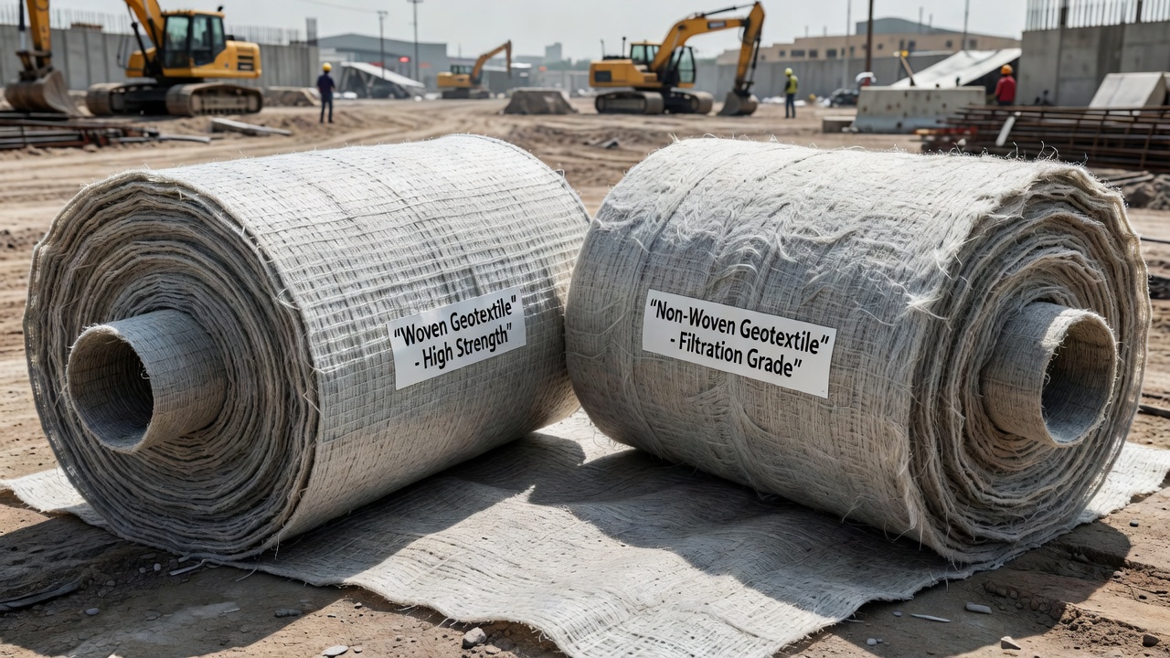
Woven geotextiles are produced by interlacing yarns or tapes on industrial looms in two perpendicular directions — the warp (machine direction along the roll length) and the weft (cross-machine direction across the roll width). The weaving pattern determines the fabric’s tensile properties, aperture geometry, and hydraulic conductivity. Woven geotextiles are characterized by high tensile strength (typically 40-140 kN/m grab strength per ASTM D4632), low elongation (5% to 25%), and defined pore structure. They have a smooth, plastic-like appearance and feel stiff compared to non-woven materials.
Slit-Film Woven Geotextiles are manufactured by extruding polypropylene into a thin film, slitting it into narrow tapes (typically 2-5 mm width), and weaving these tapes into a fabric. The tapes are rectangular in cross-section and have low permeability — water passes primarily through the inter-yarn gaps rather than through the yarn material itself. Slit-film geotextiles offer the lowest cost per unit area of any geotextile type (typically $0.50-1.00 per square meter for standard grades) and provide adequate strength for separation and stabilization applications on moderate subgrades. However, these geotextiles have the lowest permittivity values (typically 0.01-0.10 sec⁻¹), limited filtration capability, and can suffer from tape splitting under high stress. AASHTO M288-21 distinguishes slit-film geotextiles as those with elongation less than 50% (woven class).
Monofilament Woven Geotextiles are woven from continuous round or oval filaments of polypropylene, polyester, or polyethylene. The filaments have diameters of 0.2-0.8 mm and create a more open fabric structure than slit-film types. Monofilament geotextiles offer higher permittivity (0.1-1.0 sec⁻¹), better filtration performance, and greater resistance to clogging compared to slit-film materials. They are the preferred woven type for filtration and drainage applications where both strength and hydraulic performance are required. The open structure provides good aggregate interlock for base course confinement but may allow some fines passage if the aperture size exceeds the soil retention criteria.
Multifilament Woven Geotextiles are woven from bundles of dozens or hundreds of individual filaments (each 10-50 microns diameter) twisted or aligned to form a yarn. Multifilament yarns provide the highest tensile strength and modulus of any geotextile type, with grab tensile strengths exceeding 200 kN/m in high-strength products. These geotextiles are manufactured primarily from polyester (PET) for demanding permanent reinforcement applications. The multifilament structure offers excellent load-strain characteristics, creep resistance (less than 1% strain under sustained load), and good hydraulic properties when woven with controlled fabric openings. Multifilament PET geotextiles are specified for MSE walls, steep slopes, foundation reinforcement, and high-load pavement stabilization where design lives exceed 75 years.
Combination Woven Geotextiles incorporate two or more yarn types in the warp and weft directions. Typical configurations include slit-film warp with monofilament weft (providing strength in the machine direction with filtration in the cross direction) or multifilament warp with monofilament weft (maximum strength with hydraulic capacity). These hybrid constructions optimize performance for specific applications and are offered by most major geotextile manufacturers.
Non-woven geotextiles consist of randomly oriented fibers that are bonded together by mechanical entanglement (needle-punching), thermal fusion (heat-bonding/caulendering), or chemical adhesion (resin-bonding). The random fiber orientation creates a three-dimensional pore structure that provides excellent filtration and drainage characteristics. Non-woven geotextiles are characterized by high permittivity (0.5-3.0 sec⁻¹), elongation exceeding 50%, and a felt-like or fuzzy appearance. They are typically specified by mass per unit area (expressed in g/m² or oz/yd²) rather than tensile strength, though mechanical property requirements are also specified.
Needle-Punched Non-Woven Geotextiles are the most common non-woven type, accounting for approximately 70% of the non-woven geotextile market. Manufacturing involves: (1) extruding continuous filaments (PP) or opening staple fibers (PP or PET) into a loose web; (2) passing the web through a needle loom containing thousands of barbed needles (typically 100-300 needles per linear meter of loom width); (3) reciprocating the needles through the web at high speed (500-2,000 strokes per minute), entangling fibers through mechanical interlocking. The needle-punching process produces a thick, compressible fabric (typically 1-5 mm thickness at 2 kPa) with a three-dimensional pore network. Needle-punched non-wovens are available in mass per unit area from 100 g/m² (3 oz/yd²) to 1,000 g/m² (30 oz/yd²) or higher. They offer the best balance of filtration, drainage, and mechanical properties for general geotechnical applications.
Heat-Bonded Non-Woven Geotextiles (also called spunbonded or thermally-bonded) are manufactured by extruding continuous filaments, laying them into a web, and bonding them through controlled heating and pressure (caulendering). The fibers are fused at their contact points, creating a thinner, stiffer fabric (typically 0.3-1.0 mm thickness) with smaller average pore size compared to needle-punched equivalents of the same mass. Heat-bonded non-wovens have lower permittivity but superior filtration retention (ability to retain very fine soils) and higher tensile efficiency per unit mass. They are specified for applications requiring a thin, high-retention filter where soil piping must be prevented — such as wrapping drainage pipes in fine-grained soils, retaining wall drainage envelopes, and filtration layers beneath geomembranes in landfill containment systems.
Resin-Bonded Non-Woven Geotextiles are manufactured by spraying or impregnating a fiber web with chemical binders (acrylic resins, styrene-butadiene latex) that are then cured to bond the fiber matrix. These geotextiles are less common in civil engineering due to concerns about binder degradation over time and reduced environmental compatibility. Resin-bonded non-wovens are primarily used in specialized applications such as erosion control mats where temporary performance (1-5 years) is acceptable.
| Geotextile Type | Subtype | Typical Tensile (kN/m) | Typical Elongation (%) | Permittivity (sec⁻¹) | AOS (mm) | Primary Functions |
|---|---|---|---|---|---|---|
| Woven | Slit-film | 40-100 | 10-25 | 0.01-0.10 | 0.15-0.60 | Separation, Stabilization |
| Woven | Monofilament | 50-140 | 10-30 | 0.10-1.0 | 0.30-2.00 | Filtration, Drainage, Separation |
| Woven | Multifilament PET | 100-400+ | 10-15 | 0.05-0.50 | 0.20-0.80 | Reinforcement, Separation |
| Non-woven | Needle-punched | 20-100 | 50-120 | 0.50-3.0 | 0.08-0.30 | Filtration, Separation, Drainage |
| Non-woven | Heat-bonded | 15-60 | 30-70 | 0.20-0.80 | 0.05-0.15 | Filtration (fine soils), Protection |
| Non-woven | Resin-bonded | 10-40 | 40-80 | 0.30-1.5 | 0.10-0.25 | Erosion control (temporary) |
Geocomposites combine geotextile with other geosynthetic products to achieve multi-function performance in a single product. Common configurations include: geotextile-geonet composites (geotextile filter bonded to a thick drainage net core for planar flow in landfill leachate collection, retaining wall drainage, and pavement edge drains); geotextile-geomembrane composites (geotextile bonded to one or both sides of an impermeable geomembrane for protection against puncture while providing drainage across the interface); and geotextile-geogrid composites (geotextile laminated to a geogrid apertures for combined separation-filter-drainage with tensile reinforcement on soft, wet subgrades).
Moisture management (wicking) geotextiles are a recent innovation developed for pavement systems in wet climates. These geotextiles incorporate hydrophilic fibers or specialized fiber cross-sections that actively transport water laterally within the fabric plane through capillary action, reducing moisture content in the overlying pavement layers even under unsaturated conditions. Wicking geotextiles have demonstrated significant reductions in pavement moisture content and improved performance in accelerated pavement testing at Texas A&M Transportation Institute (TTI).
Biodegradable natural-fiber geotextiles are manufactured from jute, coir (coconut husk), sisal, or wood shavings for temporary erosion control applications (typically 6-24 months service life). These products provide immediate surface protection and slope stabilization until vegetation establishes, then decompose without leaving synthetic residues. Jute geotextiles (geojute) degrade within 2-5 years and are used in slope protection and riverbank stabilization. Coir geotextiles are more durable (5-10 years) due to higher lignin content and are preferred for steeper slopes and higher-energy environments.
Separation is the most widely applied geotextile function in pavement construction. It involves placing a geotextile between two dissimilar materials — typically a fine-grained subgrade soil and a coarse aggregate base course — to prevent their intermixing under traffic and environmental loading. The separation function preserves the engineering properties of both materials, maintaining the structural integrity of the pavement system over its design life.
The mechanism of subgrade contamination occurs through pumping — the migration of fine soil particles upward into the aggregate base course under repeated traffic loading. As a wheel load passes over a pavement section, the subgrade experiences a stress pulse that generates excess pore water pressure in saturated or near-saturated fine soils. This pressure forces water and suspended soil particles upward through voids in the overlying aggregate. Each load cycle transports a small quantity of fines into the base course pores. Over thousands to millions of load cycles, the base course becomes progressively contaminated with subgrade fines, a process known as aggregate degradation or fines migration.
The consequences of subgrade-aggregate intermixing are measurable and severe. Research by Giroud and Noiray (1981) demonstrated that contamination of the base course by 5-10% by weight of subgrade fines reduces its modulus by 30-50% and its drainage capacity by orders of magnitude. A clean, free-draining aggregate base may have a permeability of 10⁻² to 10⁻³ cm/sec; the same base contaminated with 10% silt-clay fines may have permeability reduced to 10⁻⁵ to 10⁻⁶ cm/sec — effectively becoming an impermeable layer. The contaminated base retains water, leading to increased pore pressures under traffic, accelerated pumping, frost heave in cold climates, and ultimately premature pavement failure through loss of structural support.
The separation geotextile acts as a physical barrier between the subgrade and aggregate. Its pore structure (characterized by AOS) is sized to prevent subgrade soil particles from passing through while still allowing water flow for drainage. The separation function is most effective when the geotextile is placed directly on the prepared subgrade prior to aggregate placement and compaction. The geotextile must satisfy both survivability requirements (sufficient strength to withstand installation stresses without tearing) and hydraulic requirements (permitting vertical drainage to prevent pore pressure buildup beneath the geotextile).
Design criteria for separation geotextiles are based on subgrade California Bearing Ratio (CBR) and construction traffic intensity:
The Giroud-Han method (developed by J.P. Giroud and Jie Han, published in the Journal of Geotechnical and Geoenvironmental Engineering, 2004) provides a mechanistic-empirical design procedure for geotextile-separated unpaved roads. The method calculates the required aggregate thickness as a function of wheel load, tire pressure, number of load passes, subgrade CBR, and geotextile improvement factor (a factor ranging from 1.0 for unreinforced to 1.5-2.5 for geotextile-reinforced sections). The aggregate thickness reduction achievable with a separation geotextile on soft subgrades (CBR 1-3) is typically 20-40% compared to an unreinforced section.
The filtration function of a geotextile involves retaining soil particles while allowing water to flow through the fabric in a controlled manner. This is the most hydraulic-critical of the geotextile functions and requires careful design to balance two competing requirements — retention (preventing soil loss) and permeability (maintaining flow capacity). Unlike a graded granular filter (which relies on particle-to-particle bridging within a multiple-layer aggregate system), a geotextile filter is a single-layer system that must achieve both retention and permeability through its own fabric structure.
The filtration mechanism in geotextiles relies on the formation of a filter bridge at the soil-geotextile interface. When water flows from the soil toward the geotextile, the finest soil particles initially pass through the fabric openings. Over time, coarser particles accumulate against the geotextile surface, creating a natural filter cake with progressively smaller pores. This filter bridge then retains the finer particles that would have passed through the geotextile alone. The geotextile must maintain this filter bridge under cyclic, reversing, or intermittent flow conditions typical of pavement drainage systems.
Three design criteria must be satisfied for geotextile filtration:
Retention Criterion: The geotextile must have sufficiently small openings to retain the soil being filtered. The governing equation per Holtz, Christopher, and Berg (1997, FHWA-HI-95-038) is:
Permittivity Criterion: The geotextile must have adequate flow capacity to pass water without excessive head buildup. The required permittivity (ψ) is calculated as:
Clogging Resistance Criterion: The geotextile must resist long-term clogging from soil particle accumulation within its pore structure. Clogging potential is assessed through the gradient ratio test (ASTM D5101), which measures the ratio of hydraulic gradient across the geotextile-soil system to the gradient across the adjacent soil alone. A gradient ratio greater than 3.0 indicates excessive clogging potential. For critical applications, the long-term flow test (ASTM D7880/NCHRP Project 24-32) evaluates sustained flow performance over 1,000 hours.
Geotextile filtration is specified for pavement trench drains, edge drains, retaining wall drainage, beneath riprap erosion protection, wrapped drainage pipes, and silt fences. The correct geotextile for filtration is almost always a non-woven needle-punched type due to its three-dimensional pore structure, high permittivity, and clogging resistance. Heavy-weight non-wovens (270-550 g/m² or 8-16 oz/yd²) are preferred for filtration under high hydraulic loads.
The drainage function refers to the ability of a geotextile to conduct water within its own plane (in-plane flow, also called transmissivity) from areas of higher hydraulic head to areas of lower head. This is distinct from the filtration function (flow through the geotextile perpendicular to its plane). In-plane drainage utilizes the geotextile’s thickness and interconnected pore structure as a conduit for lateral water movement, collecting groundwater or infiltration and conveying it to collection pipes or outlet points.
The drainage capacity of a geotextile is quantified as transmissivity (θ) — the product of in-plane permeability (k_p) and thickness (t), expressed in units of m²/sec. Transmissivity is measured per ASTM D4716 under specified normal stress (typically 10-500 kPa) and hydraulic gradient (typically 0.1-1.0). Non-woven needle-punched geotextiles exhibit transmissivity values of approximately 10⁻⁵ to 10⁻⁴ m²/sec under low normal stress (10-50 kPa), decreasing substantially under higher stress as the fabric compresses. A 100 g/m² (3 oz/yd²) non-woven geotextile to 550 g/m² (16 oz/yd²) non-woven provides transmissivity approximately proportional to mass per unit area.
Geotextile drainage design requires selecting a geotextile with sufficient transmissivity for the expected flow rate and gradient. The required transmissivity (θ_req) is calculated as:
For typical pavement edge drain applications (flow rate 0.1-1.0 L/min per meter of drain, gradient 0.01-0.10), required transmissivity ranges from 10⁻⁵ to 10⁻⁴ m²/sec — achievable with medium-weight non-woven geotextiles (200-400 g/m² or 6-12 oz/yd²) under low overburden stress.
For higher-capacity drainage applications — such as leachate collection in landfills, retaining wall heel drains, or pavement drainage blankets — the transmissivity of geotextile alone is often insufficient. In these cases, geocomposite drains (geotextile bonded to a thick, high-flow geonet core) are specified. Geocomposite drainage products provide transmissivity of 10⁻³ to 10⁻² m²/sec — 10 to 100 times that of geotextile alone — by incorporating a three-dimensional drainage core of extruded polyethylene or polypropylene that maintains flow capacity under high overburden stress.
Important design consideration: Environmental stress cracking (ESC) of geosynthetics in drainage applications has been documented in forensic studies of landfill and pavement drainage failures. Incompatible polymer combinations (polyester geotextile in contact with polyethylene drainage core at elevated temperatures) or exposure to aggressive chemicals (leachate, deicing salts, hydrocarbons) can accelerate polymer degradation. Material compatibility testing per EPA Method 9090 or ISO/TR 20432 is recommended for critical drainage applications with design lives exceeding 20 years.
The reinforcement function of a geotextile uses the fabric’s tensile strength and soil-fabric interface friction to resist tensile stresses within a soil mass that the soil alone cannot sustain. This function is fundamentally different from separation and filtration — it requires the geotextile to carry structural load and contribute to the stability of the soil-geotextile system.
Reinforcement geotextiles must have high tensile strength (typically 50-400+ kN/m per ASTM D4595 or ASTM D6637 wide-width tensile test), low creep deformation under sustained load (less than 1% strain over the design life), and adequate soil-fabric interface friction (typically 0.8-1.0 times the soil internal friction angle for non-wovens, 0.9-1.0 for woven geotextiles on granular soils, measured per ASTM D5321). High-modulus polyester (PET) multifilament woven geotextiles are the preferred reinforcement geotextile for permanent applications due to their combination of high strength, low creep, and long-term durability.
Three reinforcement mechanisms are recognized:
Lateral Restraint (Confinement): The most significant mechanism in pavement reinforcement. When aggregate is placed over a geotextile and compacted, particles penetrate through or interlock with the fabric surface. Under traffic loading, the aggregate experiences lateral tensile strains at its base. The geotextile, through friction and interlock, restrains this lateral movement, effectively providing confinement that increases the aggregate modulus. Laboratory studies have shown that geotextile confinement can increase the resilient modulus of granular base materials by 1.5 to 3 times compared to unreinforced conditions.
Improved Bearing Capacity: On soft subgrades (CBR < 3), the geotextile-reinforced aggregate base acts as a semi-rigid platform that distributes traffic loads over a wider area on the subgrade surface — analogous to the function of a snowshoe. The wider load distribution reduces vertical stress on the soft subgrade below its bearing capacity, preventing bearing failure and excessive rutting.
Membrane-Type Support: Under significant deformation (rutting > 50 mm in unpaved applications), the geotextile develops tensile membrane stresses that provide upward vertical support to the applied load. This mechanism is secondary in paved pavements (where rut depths are limited to 6-25 mm) but significant in unpaved roads and temporary construction platforms where larger deformations are acceptable.
The design methodology for reinforced unpaved roads (Giroud-Han method) incorporates these mechanisms through reinforcement factors that reduce the required aggregate thickness. The design procedure accounts for geotextile tensile strength, modulus, and soil-geotextile friction in addition to subgrade CBR, traffic loading, and wheel configuration.
AASHTO M288-21 (Standard Specification for Geotextile Specification for Transportation Applications) is the governing material specification for geotextiles in transportation infrastructure across the United States and is referenced by the Federal Highway Administration, Airport authorities, and nearly all state Departments of Transportation. It supersedes earlier Task Force 25 guidelines and AASHTO M288 editions (2006, 2012, 2017).
AASHTO M288 classifies geotextiles into three survivability classes reflecting the severity of installation conditions:
| Survivability Class | Installation Severity | Subgrade CBR | Aggregate Size | Construction Traffic | Retention Requirements |
|---|---|---|---|---|---|
| Class 1 | Severe | < 1 to < 3 | 50-150 mm | High (dump trucks, scrapers) | Exhumed samples must retain ≥ 70% of MARV tensile strength |
| Class 2 | Moderate | 3 to 7 | 25-75 mm | Moderate (dump trucks, pickups) | Exhumed samples must retain ≥ 50% of MARV tensile strength |
| Class 3 | Low | > 7 | < 50 mm | Light (pickups, rollers) | Exhumed samples must retain ≥ 40% of MARV tensile strength |
Within each class, the specification distinguishes woven geotextiles (elongation < 50% at failure per ASTM D4632) from non-woven geotextiles (elongation > 50% at failure). The Minimum Average Roll Values (MARV) — defined as the mean minus two standard deviations — are specified for each class:
| Property | Test Method | Class 1 Woven (<50%) | Class 1 NW (>50%) | Class 2 Woven (<50%) | Class 2 NW (>50%) | Class 3 Woven (<50%) | Class 3 NW (>50%) |
|---|---|---|---|---|---|---|---|
| Grab tensile strength (N) | ASTM D4632 | 1,400 | 900 | 1,100 | 700 | 900 | 500 |
| Sewn seam strength (N) | ASTM D4632 | 1,260 | 810 | 990 | 630 | 810 | 450 |
| Tear strength (N) | ASTM D4533 | 500 | 350 | 400 | 250 | 300 | 180 |
| Puncture strength (N) | ASTM D6241 | 3,375 | 2,200 | 2,650 | 1,700 | 2,200 | 1,375 |
| Burst strength (kPa) | ASTM D3786 | 5,500 | 3,500 | 4,400 | 2,750 | 3,500 | 2,200 |
| Permittivity (sec⁻¹) | ASTM D4491 | 0.02 | 0.70 | 0.02 | 0.70 | 0.02 | 0.70 |
| AOS (mm) | ASTM D4751 | 0.43 max | 0.43 max | 0.43 max | 0.43 max | 0.43 max | 0.43 max |
| UV stability (% retention after 500 hrs) | ASTM D4355 | 70 | 70 | 70 | 70 | 70 | 70 |
Application-specific requirements within AASHTO M288 further define property needs:
| Application | AOS Requirement | Permittivity Requirement | Survivability |
|---|---|---|---|
| Subsurface Drainage (< 15% fines) | 0.43 mm max | 0.02 sec⁻¹ min | Class 2 minimum |
| Subsurface Drainage (15-50% fines) | 0.25 mm max | 0.02 sec⁻¹ min | Class 2 minimum |
| Subsurface Drainage (> 50% fines) | 0.25 mm max | 0.02 sec⁻¹ min | Class 2 minimum |
| Separation | 0.43 mm max | 0.02 sec⁻¹ min | Class 1-3 per subgrade CBR |
| Permanent Erosion Control | 0.43 mm max | 0.02 sec⁻¹ min | Class 1-2 per CBR |
| Paving Fabric | N/A | N/A | Type I or II per binder content |
The NTPEP program (National Transportation Product Evaluation Program) provides a centralized geotextile testing and qualification system for AASHTO member states. Geotextile manufacturers submit products for NTPEP evaluation every 2-3 years, including conformance testing (verification of MARV compliance) and audit testing (independent laboratory verification). State DOTs reference the NTPEP database for approved product lists (APLs) when specifying geotextile products.
Geotextiles serve multiple functions within pavement structures depending on placement location, material type, and design objectives. The principal pavement applications are:
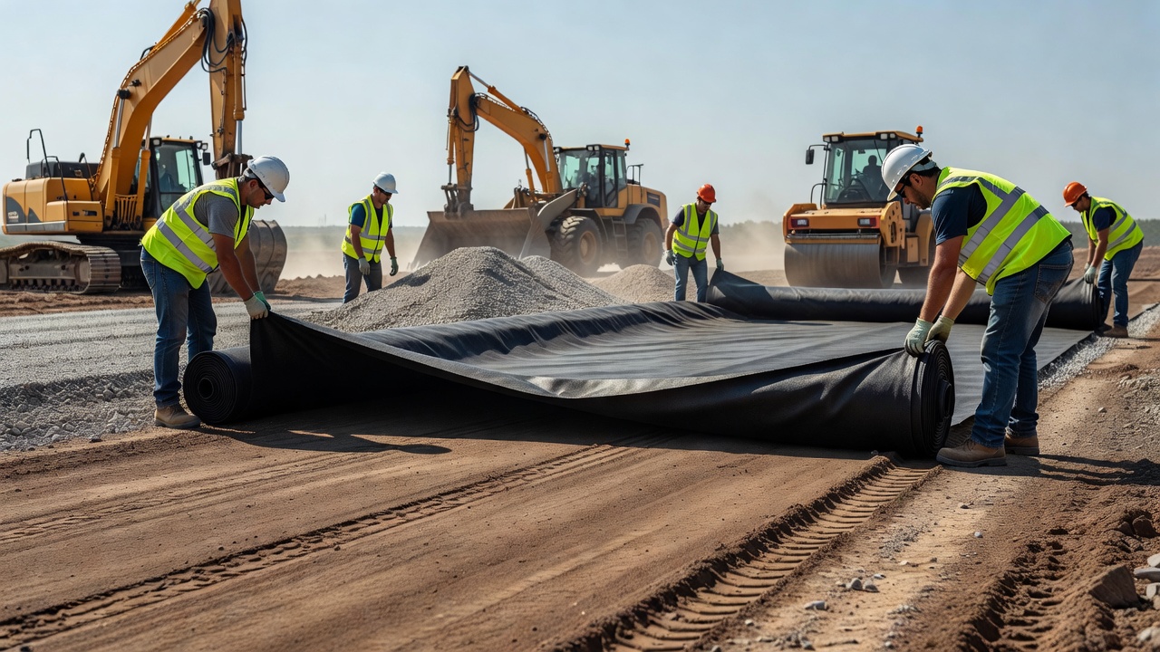
Subgrade Separation and Stabilization: The most common pavement application. A non-woven needle-punched geotextile (or woven for higher strength requirements) is placed directly on the prepared subgrade before aggregate base placement. The geotextile prevents subgrade-aggregate intermixing (separation), provides construction access over soft subgrades (stabilization), and may contribute to load distribution (reinforcement). TxDOT DMS-6200 (Filter Fabric) and FAA Item P-156 specify geotextile requirements for subgrade separation in highway and airport pavements respectively. The standard placement sequence is: (1) grade and compact subgrade, (2) proof-roll to identify soft spots, (3) roll geotextile on subgrade with shingled overlaps, (4) anchor edges with staples or sandbags, (5) place initial aggregate lift (minimum 150 mm) without tracking on geotextile, (6) compact aggregate to specification, (7) complete remaining pavement layers.
Asphalt Overlay Interlayer (Reflective Crack Control): Geotextile placed between an existing cracked pavement and an asphalt overlay as a stress-relief interlayer. The geotextile — typically a lightweight non-woven (120-150 g/m² or 3.5-4.5 oz/yd²) saturated with asphalt binder at a rate of 0.9-1.8 L/m² — serves to: absorb tensile stresses at the crack tip, delay crack propagation from the existing pavement into the overlay, and provide an impermeable moisture barrier beneath the overlay. TTI Research Report 0-1777 (TxDOT) established that interlayer effectiveness depends on tack coat application rate, overlay thickness (minimum 40 mm), and crack opening width (effective range 0.03-0.07 inches for Fiberglass + PET composites). Paving fabrics are specified under AASHTO M288 Type I (original binder content < 6.5%) or Type II (≥ 6.5%) and TxDOT DMS-6220 (Fabric for Underseals).
Pavement Edge Drains: Geotextile-wrapped aggregate trench drains installed along pavement edges to intercept and remove subsurface water from the pavement structure. The geotextile (typically non-woven needle-punched, 200-300 g/m²) wraps the aggregate trench and drain pipe, functioning as a filter to prevent soil migration into the drain while allowing water inflow. Per AASHTO M288 subsurface drainage requirements, the geotextile AOS must be ≤ 0.43 mm for soils with < 15% fines, and permittivity must be ≥ 0.02 sec⁻¹. Edge drains are typically spaced at 50-200 m intervals along the pavement edge, connected to outfall pipes or daylighted at low points.
Working Platform Stabilization: On very soft subgrades (CBR < 1), geotextile reinforced aggregate layers provide a construction platform capable of supporting heavy equipment required for subsequent pavement construction. Multiple geotextile layers or geotextile-geogrid composites may be required for extreme conditions. ERDC (US Army Engineer Research and Development Center) research at the NAPTF (National Airport Pavement Test Facility) demonstrated Traffic Benefit Ratios (TBR) of 3.3 to 29.7 for geotextile-stabilized sections on low-CBR subgrades under heavy aircraft loading.
| Pavement Application | Geotextile Type | Mass (g/m²) | Survivability Class | Critical Properties |
|---|---|---|---|---|
| Subgrade separation (CBR 3-7) | NW needle-punched | 160-270 | Class 2 | Grab ≥ 700N, AOS ≤ 0.43 mm, Perm ≥ 0.02 sec⁻¹ |
| Subgrade stabilization (CBR 1-3) | Woven slit-film or NW heavy | 270-550 | Class 1 | Grab ≥ 1400N (woven) or 900N (NW), Puncture ≥ 3375N (woven) |
| Reflective crack interlayer | Heat-bonded NW | 120-150 | Paving fabric | Asphalt retention ≥ 0.9 L/m², melting point > 165°C |
| Edge drain wrap | NW needle-punched | 200-300 | Class 2 (drainage) | AOS ≤ 0.25 mm (if fines > 15%), Perm ≥ 0.02 sec⁻¹ |
| Working platform (CBR < 1) | Composite or high-strength PET | 400-800+ | Class 1 or better | Grab ≥ 2000N, high puncture resistance |
Geotextiles are extensively used for both permanent and temporary erosion control in slope, channel, shoreline, and construction site applications.
Permanent Erosion Control: Non-woven needle-punched geotextiles (270-550 g/m² or 8-16 oz/yd²) are placed beneath riprap, rock armor, concrete block revetments, or gabion mattresses along channels, shorelines, and steep slopes. The geotextile functions as a filter layer — retaining the underlying soil while allowing groundwater seepage and wave-induced hydraulic flows to pass through the armor layer without transporting soil particles. This prevents suffusion (internal erosion of fine soil particles through the armor voids) and scour (removal of soil from beneath the armor due to hydraulic forces). Per AASHTO M288, permanent erosion control geotextiles must meet Class 1 survivability requirements when subgrade fines exceed 15% and the armor stone size exceeds 150 mm. Placement requires a smooth subgrade surface (free of sharp protrusions), minimum 300 mm overlap at joints, and immediate coverage with armor material to prevent UV damage.
Temporary Erosion Control: Lighter-weight geotextiles and erosion control blankets (ECBs) provide immediate surface protection on newly graded slopes until vegetation establishes. Rolled Erosion Control Products (RECPs) include: erosion control blankets (jute, coir, straw, or wood fiber nets, typically 6-24 months functional life) for slope surface protection; turf reinforcement mats (TRMs) (synthetic fiber webs with high tensile strength, permanent UV-stabilized) for high-flow channels and steep slopes requiring long-term reinforcement; and silt fences (woven or non-woven geotextile on wire or post supports, 0.6-1.2 m height) for sediment control at construction site boundaries. AASHTO M288 includes temporary silt fence geotextile requirements: minimum grab tensile strength of 400 N (MD) and 290 N (CMD) per ASTM D4632, maximum AOS of 0.60 mm per ASTM D4751, and UV stability of 70% strength retention after 500 hours per ASTM D4355.
Design guidance for erosion control geotextiles is provided by the FHWA HEC-15 (Design of Roadside Channels with Flexible Linings), the USDA Natural Resources Conservation Service, and the Erosion Control Technology Council (ECTC). The primary design parameters are: permissible shear stress of the geotextile-soil system (typically 5-50 Pa for vegetated systems, 50-250 Pa for geotextile-reinforced riprap), permissible velocity of flow (typically 1-6 m/sec), and factor of safety against geotextile uplift (minimum 1.5 for submerged conditions).
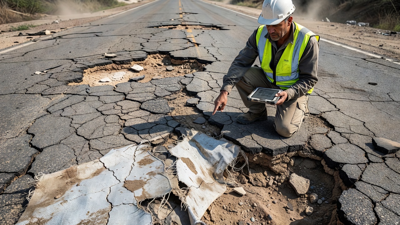
Field inspection of geotextile in pavement structures becomes critical when the geotextile becomes exposed at the pavement edge, at erosion sites, at construction cuts, or through pavement failures. Exposed geotextile indicates that the overlying cover material (aggregate base or asphalt) has been lost or displaced, and the geotextile’s protective function has been compromised. Inspection follows a systematic methodology to document condition, identify failure mechanisms, and recommend corrective action.
Causes of Geotextile Exposure:
Distress Indicators During Inspection:
| Distress Type | Description | Significance | Trigger for Action |
|---|---|---|---|
| Tears and punctures | Holes, cuts, or rips > 50 mm in any dimension | Loss of separation/filtration, risk of subgrade pumping | Any tear > 100 mm or multiple tears within 1 m² requiring repair |
| UV degradation | Embrittlement, discoloration, surface cracking, strength loss | Material becomes brittle, loses tensile capacity, fractures under handling | Brittle fracture visible; strength retention < 50% per field extraction test |
| Fraying at exposed edges | Fiber unraveling at cut edges, progressive loss of fabric integrity | Active deterioration spreading from exposed edge | Fraying extending > 50 mm from edge |
| Clogging | Surface covered with soil or organic film, reduced permeability indicated by ponding | Loss of filtration and drainage capacity; pore blockage reduces service life | Standing water on geotextile surface > 24 hours after rainfall |
| Loss of cover material | Aggregate or asphalt missing above geotextile over area > 0.5 m² | Structural failure — pavement has lost load distribution capacity | Immediate repair required — traffic hazard |
| Displacement | Geotextile shifted from original position, wrinkles or folds present | Loss of design function, potential localized stress concentration | Any measurable displacement from specified position |
| Biological intrusion | Root penetration through geotextile, animal burrowing beneath | Physical damage to fabric, preferential flow path creation | Root penetration > 5 mm diameter or extensive distribution |
Inspection Methodology:
Action Levels Based on Inspection Findings:
Post-Failure Investigation Protocol: When geotextile exposure is associated with pavement structural failure, the investigation should follow this protocol:
Documentation and Reporting: All geotextile inspection findings should be documented in a standardized format including: project identifier, feature/location (route, station, offset), date of inspection, inspector name, exposed geotextile dimensions, distress types and measurements, photographs (minimum 3 — overall exposure, close-up of worst damage, detail of edge condition), severity classification (Action Level 1/2/3), recommended repair method and urgency, and follow-up inspection date.
Proper handling and installation are essential for geotextile performance. Field surveys consistently indicate that more than 80% of geotextile “failures” are attributable to installation errors rather than material defects.
Subgrade Preparation: The subgrade receiving the geotextile must be graded smooth, compacted to project specifications, and free of sharp objects (stones > 50 mm, tree roots, construction debris) that could puncture the fabric during placement and cover operations. Soft spots identified during proof-rolling should be excavated and replaced with select fill before geotextile placement.
Roll Handling: Geotextile rolls should be lifted with a spreader bar or forklift with carpet poles — never with chains or straps that could crush the roll core. Rolls should be stored off the ground on pallets, covered with UV-opaque tarps, and protected from moisture, chemicals, and temperatures exceeding 60°C. Storage duration should not exceed manufacturer recommendations (typically 6-12 months).
Placement: The geotextile is unrolled manually on the prepared subgrade. The machine direction (roll length direction) should be oriented parallel to the direction of anticipated traffic or principal load direction. Adjacent rolls are placed with overlaps as specified (typically 300-600 mm for subgrade CBR ≥ 3, 600-900 mm for CBR < 3). Overlaps should be shingled — each subsequent roll placed over the edge of the previous roll — so that advancing fill material does not push the geotextile apart at joints.
Tensioning: The geotextile should be placed with sufficient tension to remove wrinkles and folds but not stretched beyond its elastic limit. Wrinkles create stress concentration points where aggregate can punch through during compaction. Loose fabric can fold and create voids in the aggregate layer.
Anchoring: Geotextile edges should be anchored with pins (typically 150-300 mm long U-shaped steel wire staples with washers), sandbags, or temporary aggregate piles at intervals of 1-2 m to prevent wind uplift and displacement before cover placement.
Cover Placement: The initial aggregate lift must be placed immediately after geotextile placement — minimum 150 mm loose thickness, placed from the far end toward the anchoring point (reverse dumping) to prevent direct equipment travel on exposed geotextile. No tracked equipment (dozers, excavators) should operate directly on geotextile — a minimum 150 mm aggregate cushion is required. Rubber-tired equipment may operate on geotextile over competent subgrade (CBR > 4) at slow speed (< 15 km/h) with limited turning.
UV Exposure: Geotextile should not be exposed to direct sunlight for more than 14-30 days for unprotected polypropylene, or 3-6 months for UV-stabilized products (2-3% carbon black). UV damage is cumulative — even covered geotextile can degrade if left exposed at edges or overlaps. In tropical or high-altitude environments with high UV levels, exposure limits should be reduced by 50%.
Repair of Damaged Geotextile: Any geotextile damaged during installation must be repaired by placing a patch of the same material extending a minimum of 1 m beyond the damaged area in all directions. The patch should be field-sewn (using a portable sewing machine with UV-stabilized thread) or overlapped a minimum of 300 mm and secured with pins at 300 mm spacing. Torn areas exceeding 1 m² require complete replacement of the affected section.
For quick reference in specification and inspection activities:
| Parameter | Value | Test Method | Application |
|---|---|---|---|
| AASHTO M288 Class 1 grab tensile (woven) | ≥ 1,400 N | ASTM D4632 | Severe installation, soft subgrade |
| AASHTO M288 Class 1 grab tensile (non-woven) | ≥ 900 N | ASTM D4632 | Severe installation, soft subgrade |
| AASHTO M288 Class 2 grab tensile (woven) | ≥ 1,100 N | ASTM D4632 | Typical pavement separation |
| Minimum permittivity (drainage/separation) | ≥ 0.02 sec⁻¹ | ASTM D4491 | All subsurface drainage and separation |
| Maximum AOS (drainage, < 15% fines) | ≤ 0.43 mm (#40 sieve) | ASTM D4751 | Subsurface drainage applications |
| Maximum AOS (drainage, > 15% fines) | ≤ 0.25 mm (#60 sieve) | ASTM D4751 | Fines-rich soil drainage |
| FAA permittivity requirement | ≥ 0.02 sec⁻¹ | ASTM D4491 | Airport pavement P-156 |
| FAA AOS requirement | ≤ 0.60 mm | ASTM D4751 | Airport pavement P-156 |
| Minimum UV strength retention (500 hrs) | ≥ 70% | ASTM D4355 | Any exposed installation |
| Minimum cover thickness over geotextile | 150 mm | — | Before trafficking |
| Minimum overlap (CBR ≥ 3) | 300 mm | — | Standard overlap |
| Minimum overlap (CBR < 3) | 600-900 mm | — | Soft subgrade overlap |
| Maximum UV exposure (PP, unprotected) | 14-30 days | — | Manufacturer dependent |
| Giroud-Han modulus improvement factor | 1.5-2.5 | — | Reinforced unpaved road design |
TarmacView provides advanced infrastructure inspection solutions. Our team understands how geotextile condition affects pavement performance. Contact us to discuss how data-driven inspection methods can improve your geotextile-reinforced pavement evaluation programs.
Geogrids are high-strength polymer grids used to reinforce soil, aggregate, and asphalt layers, improving load distribution, reducing rutting, and extending pav...
Subsurface drainage systems — edge drains, underdrains, permeable bases, and drainage blankets — remove water from pavement structural layers, preventing pumpin...
Retaining walls are engineered earth-retaining structures that hold back soil or rock from buildings, bridge approaches, roadways, and airport facilities, preve...