Gimbal – Camera Stabilization System for Drone Inspection
A gimbal is a motorized, stabilized mount that isolates a camera or payload from drone movement and vibration, maintaining steady orientation for sharp, consistent imagery. 3-axis gimbals (pitch, roll, yaw) are standard for inspection drones. Covers gimbal types, stabilization accuracy, nadir/oblique imagery consistency, and gimbal calibration.
Gimbal – Camera Stabilization System for Drone Inspection
What is a Gimbal?
A gimbal is a precision electromechanical mount that actively stabilizes a camera, sensor, or other payload against aircraft motion, vibration, and external disturbances. In drone-based infrastructure inspection, the gimbal is the critical interface between the unmanned aerial vehicle (UAV) and the imaging payload — its performance directly determines whether the captured imagery is sharp enough for measurement, geometrically consistent enough for photogrammetry, and accurate enough for sub-millimeter defect detection.
The term originates from the mechanical gimbals used for centuries in maritime compasses and scientific instruments — nested rings that allowed a device to remain level regardless of the platform’s orientation. Modern drone gimbals replace these passive mechanical rings with active electromechanical systems capable of correcting angular deviations thousands of times per second. A typical inspection drone gimbal consists of three brushless DC motors (one per rotational axis), an inertial measurement unit (IMU) with gyroscopes and accelerometers sensing angular motion at 1-8 kHz, absolute position encoders providing feedback at 0.01-0.1° resolution, and a dedicated microcontroller executing closed-loop PID control algorithms at loop rates of 1-10 kHz.
Without a gimbal, the raw vibration of a multirotor drone — typically 0.5-2.0° of angular oscillation in the 15-100 Hz frequency band — would render every image unusably blurred. The gimbal’s combined passive and active stabilization reduces this vibration by 95-99%, transmitting less than 0.01-0.05° of residual motion to the camera. This level of stabilization enables shutter speeds as slow as 1/60 second at 20 mm focal length while maintaining pixel-sharp imagery, which is essential for low-light inspection conditions such as bridge soffits, tunnel interiors, and shaded infrastructure faces.
Purpose of the Gimbal: Vibration Isolation and Orientation Control
The gimbal serves two fundamentally distinct but complementary functions: vibration isolation and orientation control. These functions address the two primary ways that drone motion degrades image quality and photogrammetric accuracy.
Vibration Isolation
Multirotor drones generate broadband vibration from multiple sources. The propulsion system (propellers spinning at 4,000-10,000 RPM combined with motors operating at their electrical commutation frequency) produces fundamental vibration at the propeller RPM frequency and harmonics extending into the hundreds of Hertz. The airframe structure amplifies certain frequencies through resonance. Wind gusts and turbulent air create low-frequency angular disturbances below 5 Hz. Flight control corrections (the flight controller’s rapid attitude adjustments, typically at 100-400 Hz) produce high-frequency micro-motions.
Passive vibration isolation is the first defense. Elastomeric dampeners — typically silicone rubber grommets or neoprene isolators — are placed between the drone’s hard-mounted airframe and the gimbal suspension arm. These components act as mechanical low-pass filters, allowing low-frequency orientation changes to pass through while blocking high-frequency vibration. The isolators are carefully tuned to cut off frequencies above 15-30 Hz, matching the dominant vibration band of the multirotor platform. The stiffness and damping coefficient of the elastomer must be selected for the specific payload mass — a gimbal designed for an 800 g camera will not dampen properly with a 400 g or 1200 g payload, as the resonant frequency shifts with mass.
Active vibration isolation is provided by the gimbal’s closed-loop motor control. Even after passive filtering, residual vibration reaches the gimbal’s IMU. The gyroscope measures angular velocity at 1-8 kHz, and the PID controller commands the brushless motors to produce equal-and-opposite torque, canceling the detected motion. The combined system achieves transmissibility of less than 0.05 — meaning 95% of the incoming vibration energy is removed before reaching the camera. This performance is quantified in the gimbal’s angular stabilization accuracy specification, typically expressed as the root-mean-square (RMS) residual angular error in degrees: 0.02-0.05° for consumer gimbals, 0.003-0.01° for professional inspection gimbals.
Orientation Control
The gimbal’s second function is to control the camera’s pointing direction independently of the drone’s attitude. The drone may be pitched forward 15° for forward flight, rolled 10° in a turn, and yawing continuously to follow a flight path — but the gimbal can keep the camera pointing straight down for nadir capture, tilted 45° for oblique capture, or locked on a specific point of interest regardless of the aircraft’s orientation.
This decoupling is achieved through the gimbal’s three-axis design. The flight controller sends the gimbal a desired orientation — for example, pitch = -90° (straight down, nadir), roll = 0°, yaw = 45° (camera facing northeast). The gimbal’s closed-loop control system maintains this orientation as the drone maneuvers around it. If the drone rolls 10° to the right during a turn, the gimbal’s roll motor simultaneously rotates the camera 10° in the opposite direction, keeping the image horizon perfectly level.
Orientation control operates in three modes that are selectable by the drone pilot or flight planning software:
Mode
Pitch Behavior
Roll Behavior
Yaw Behavior
Use Case
Follow (default)
Stays at commanded angle, independent of drone pitch
Independent of drone roll
Camera yaw tracks drone heading
Standard aerial photography, grid missions
FPV (first-person view)
Mirrors drone pitch
Mirrors drone roll
Mirrors drone yaw
Manual flight, obstacle avoidance, FPV flying
Lock (free mode)
Independent of drone pitch
Independent of drone roll
Independent of drone yaw — camera maintains fixed compass heading
Orbital inspection, point-of-interest tracking, corridor surveys
For infrastructure inspection, Lock mode is the most valuable. The camera maintains a constant heading regardless of the drone’s flight path. In a bridge deck inspection, the gimbal can be locked at nadir with a fixed yaw orientation, and all images in the grid mission will share the same compass heading — eliminating orientation discontinuities between flight strips that complicate photogrammetric feature matching. For vertical structure inspection (towers, chimneys, building facades), the gimbal is locked at an oblique angle and the drone orbits the structure while the camera continuously faces the target.
3-Axis Stabilization: Pitch, Roll, and Yaw
A 3-axis gimbal provides active stabilization and controllable orientation around three orthogonal rotational axes. Each axis is served by a dedicated brushless DC motor, position encoder, and PID control loop. The three axes are mechanically arranged in a nested configuration — the yaw motor sits at the top (closest to the drone), the roll motor in the middle, and the pitch motor at the bottom (directly driving the camera).
Pitch Axis
Pitch is rotation around the camera’s lateral axis — tilting the camera up (toward the horizon) or down (toward the ground). In the drone gimbal convention, pitch ranges from 0° (horizontal, pointing straight ahead) to -90° (vertical, pointing straight down at nadir). Positive pitch angles tilt the camera above the horizon, though this is uncommon in inspection missions.
The pitch axis is the most active during inspection flights. Nadir imaging requires pitch = -90° ± the gimbal’s stabilization tolerance. Oblique imaging for facade inspection typically uses pitch angles of -30° to -60°, depending on the structure height and standoff distance. The pitch motor must continuously counteract the drone’s forward/backward pitching during flight — when the drone pitches forward 15° to accelerate, the gimbal pitch motor rotates the camera 15° in the opposite direction to maintain the commanded pitch angle.
Pitch axis performance is specified by: angular range (typically -135° to +45° for inspection gimbals, with -135° enabling upward-looking shots of bridge soffits and tunnel roofs), maximum pitch speed (typically 30-60°/s for rapid reorientation between nadir and oblique missions), and pitch stabilization accuracy (typically 0.003-0.01° for professional gimbals).
Roll Axis
Roll is rotation around the camera’s longitudinal axis — tilting the image horizon. In an ideal inspection mission, roll remains at 0° (perfectly level horizon) at all times. The roll motor continuously counteracts the drone’s lateral rolling during turns, wind gusts, and flight corrections.
Roll stabilization is critical for photogrammetric overlap consistency. A 1° roll error between adjacent images changes the effective sidelap by approximately 1.7% of the swath width at 100 m altitude with a 24 mm equivalent lens. For a mission planned at 80% sidelap, a persistent 2° roll disturbance reduces actual overlap to 76.6% — still acceptable. However, a 5° roll event (possible in gusty wind or aggressive turns) reduces overlap to 71.5%, approaching the 60% minimum threshold below which photogrammetric reconstruction fails.
Roll axis specifications include: angular range (typically -45° to +45° for inspection gimbals), maximum roll speed (30-60°/s), and stabilization accuracy. High-end inspection gimbals maintain roll within ±0.005° during straight-and-level flight and within ±0.05° during aggressive maneuvering.
Yaw Axis
Yaw is rotation around the vertical axis — the camera’s compass heading. The yaw motor controls which direction the camera faces. Unlike pitch and roll, which primarily stabilize against drone motion, yaw also provides intentional reorientation of the camera’s field of view.
Yaw stabilization faces unique challenges. The yaw axis carries the combined mass of the entire camera assembly plus the pitch and roll motor assemblies, requiring higher torque and more robust bearings. The yaw motor must pass electrical signals (power, video, data) between the drone and the camera — this is accomplished through slip rings or flexible ribbon cables, which introduce friction and drag that the yaw motor must overcome.
Yaw axis specifications include: unlimited 360° continuous rotation (most inspection gimbals), maximum yaw speed (30-120°/s for rapid orbit scanning), and yaw stabilization accuracy (typically 0.01-0.05° — wider than pitch/roll due to magnetometer noise and slip ring friction). For systems without a magnetometer, yaw is maintained by gyroscope integration alone, which drifts at 0.1-1.0°/hour and requires periodic correction.
Axis
Range (Inspection)
Typical Stabilization Accuracy
Primary Disturbances
Pitch
-135° to +45°
0.003-0.01°
Drone pitch from acceleration/deceleration, wind gusts
Roll
-45° to +45°
0.003-0.01°
Drone roll from turns, lateral wind
Yaw
360° continuous
0.01-0.05°
Drone yaw from heading changes, magnetic interference
Gimbal Mechanics: Brushless Motors, IMU Feedback, and PID Control
The gimbal’s stabilization performance depends on the integration of three core technologies: brushless DC motors for actuation, inertial sensors for motion detection, and PID control algorithms for real-time correction.
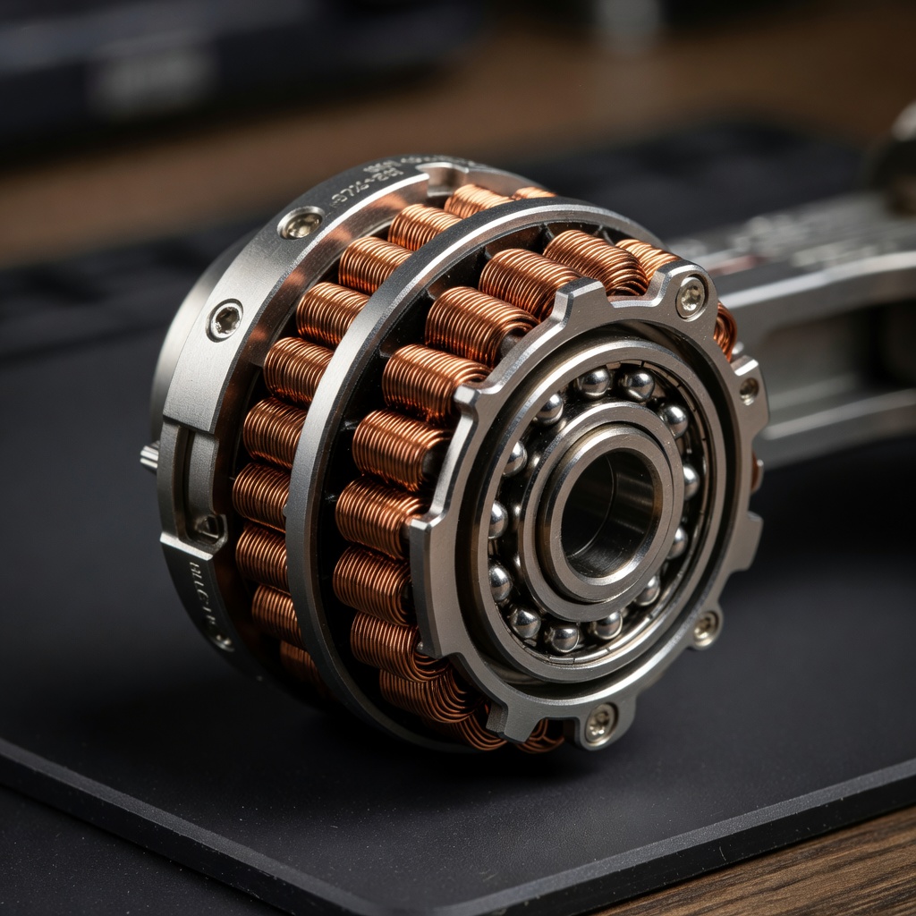
Brushless DC Motors
Gimbal motors are specialized brushless DC (BLDC) motors optimized for low-speed, high-torque, smooth operation — the opposite of typical propulsion BLDCs designed for high-speed rotation. They are characterized by high pole count (14-28 poles), low KV rating (typically 20-100 RPM/V for gimbal applications compared to 800-2000 RPM/V for propulsion motors), and slotless stator designs that eliminate cogging torque.
Cogging torque is the magnetic resistance that occurs when the permanent magnets in the rotor align with the steel teeth (slots) in the stator. In slotted motors, this creates a jerky, stick-slip motion at low rotational speeds — the very motion that is most visible in camera footage. Slotless gimbal motors eliminate cogging by removing the stator teeth, using a distributed winding embedded in the air gap. The result is perfectly smooth torque output even at rotational speeds below 1°/s, enabling the gimbal to hold a static position or perform micro-adjustments without visible stepping.
Torque constant (Kt) is a critical gimbal motor parameter, representing the torque produced per unit of current (Nm/A). A high Kt motor (typically 0.05-0.20 Nm/A for gimbal motors) generates sufficient holding torque to support the camera against gravity and acceleration forces while drawing minimal current. The holding torque must exceed the static imbalance torque — the torque produced by the payload’s center of mass being offset from the gimbal’s axis of rotation. Proper gimbal balancing (achieved by adjusting the camera position on the mounting plate and adding counterweights on the yaw arm) reduces the static imbalance torque to near zero, allowing the motors to operate efficiently.
Encoder feedback provides absolute position information for each axis. High-end gimbals use optical or magnetic absolute encoders with 14-18 bit resolution, providing position feedback accurate to 0.01-0.05°. The encoder reading is used as the reference for the PID controller’s position loop and as the source of gimbal angle metadata recorded in image EXIF tags.
IMU Feedback
The gimbal’s inertial measurement unit (IMU) is the sensing component that detects angular motion. It contains a 3-axis MEMS (micro-electro-mechanical systems) gyroscope measuring angular velocity and a 3-axis accelerometer measuring linear acceleration. Some gimbals also include a 3-axis magnetometer for absolute yaw reference.
The gyroscope is the primary sensor for stabilization. It measures angular velocity in degrees per second (°/s) around each axis at sampling rates of 1-8 kHz. The gyroscope’s bias stability — the drift of the measured angular rate when the sensor is stationary — is the dominant error source for gimbal drift. MEMS gyroscopes achieve bias stability of 0.1-1.0°/hour for consumer grades and 0.01-0.1°/hour for industrial grades. Temperature compensation models embedded in the gimbal firmware reduce bias drift by subtracting a temperature-calibrated bias value.
The accelerometer measures the direction of gravity (specifically, the vector sum of gravity and linear acceleration) and provides a long-term reference for pitch and roll orientation. While the gyroscope provides high-frequency angular rate information, it drifts over time due to bias integration (the well-known gyroscope drift problem). The accelerometer’s gravity vector measurement corrects this low-frequency drift through a sensor fusion algorithm — typically a complementary filter or Kalman filter that combines the gyroscope’s high-frequency accuracy with the accelerometer’s low-frequency stability.
The magnetometer provides absolute yaw reference relative to the Earth’s magnetic field. However, magnetometers are susceptible to interference from nearby ferrous metals and electrical currents — significant on a drone platform with powerful motors and battery currents. Gimbal yaw stability is therefore more challenging than pitch/roll stability, and magnetic calibration (compensation for hard-iron and soft-iron distortion) is essential for reliable yaw performance.
PID Control
The PID (Proportional-Integral-Derivative) controller is the algorithm that converts IMU measurements into motor commands. It is the core of the gimbal’s closed-loop control system, executing at 1-10 kHz on a dedicated microcontroller.
Where e(t) is the error signal — the difference between the target angle and the measured angle (in position control mode) or between the target angular rate and the measured angular rate (in rate control mode).
The proportional term (Kp) produces a motor command proportional to the current error. If the camera is 1° off target, the motor receives a command proportional to 1°. If it is 5° off, the command is proportionally larger. Increasing Kp makes the gimbal respond faster to disturbances, but excessive Kp causes oscillation around the target point.
The integral term (Ki) sums the error over time, eliminating steady-state error caused by gravity imbalance, friction, or continuous external torque. The integral term slowly accumulates until it produces just enough motor torque to cancel the constant disturbance. However, integral windup (excessive accumulation during large errors) can cause overshoot and oscillation, requiring anti-windup algorithms.
The derivative term (Kd) predicts future error based on the current rate of change, adding damping to the control response. The derivative term resists rapid changes in error, preventing oscillation and enabling higher Kp gains without instability. In gimbal applications, the derivative term is critical for high-frequency disturbance rejection — it commands the motor to resist change before the error becomes large.
The three PID gains (Kp, Ki, Kd) must be carefully tuned for each gimbal and payload combination. Improper tuning causes visible artifacts: low Kp produces sluggish response (the camera wobbles after a disturbance), high Kp with low Kd produces oscillation, and high Ki with high Kp produces overshoot and ringing. Professional gimbals implement automatic gain scheduling, adjusting PID parameters based on the current flight condition — higher gains during aggressive maneuvering, lower gains during stabilized hover.
Gimbal Accuracy and Drift
Gimbal accuracy is quantified by two parameters: angular stabilization accuracy (the residual angular error during active stabilization) and angular drift (the slow change in the camera’s orientation reference over time).
Angular Stabilization Accuracy
This is the RMS residual angular motion of the camera during typical flight conditions, expressed in degrees. For a stationary drone (hover), a professional inspection gimbal achieves 0.003-0.005° RMS — meaning the camera’s optical axis moves less than 0.005° from its target. At 100 m altitude, this translates to less than 1 cm of ground point displacement. Under forward flight at 10 m/s, the accuracy degrades to 0.01-0.02° RMS due to aerodynamic buffeting and propulsion vibration.
The propagation of gimbal angular error to ground point error follows the tangent relationship:
Gimbal drift is the slow angular deviation of the camera from the commanded orientation over time, caused by gyroscope bias integration. Even the highest-quality MEMS gyroscopes have residual bias after temperature compensation — typically 0.001-0.01°/s of bias. When this bias is integrated over a 30-minute flight, the accumulated yaw drift can reach 1.8-18°.
Drift is managed through several techniques:
Accelerometer correction: The accelerometer’s gravity vector measurement continuously corrects pitch and roll drift, limiting these axes to 0.1-0.5° drift over 30 minutes.
Magnetometer correction: Yaw drift is corrected by the magnetometer, though magnetic interference limits this correction to 1-5° accuracy.
GNSS heading: Dual-antenna RTK GNSS systems provide yaw accuracy of 0.1-0.5°, completely eliminating yaw drift in high-end systems.
Periodic re-initialization: The gimbal returns to a known reference position (typically at the start of each flight strip) and resets its drift accumulation.
Nadir vs Oblique Gimbal Positions for Inspection
The gimbal’s pitch articulation enables two fundamentally different image capture geometries: nadir (camera pointing straight down, perpendicular to the ground) and oblique (camera tilted between 30° and 60° from vertical). Each geometry provides complementary information for infrastructure inspection.
Nadir Capture (Pitch = -90°)
Nadir imagery captures top-down views of horizontal surfaces. In infrastructure inspection, nadir imaging is used for: road pavement condition assessment (crack mapping, rutting, pothole detection), bridge deck surface evaluation, roof condition surveys, solar panel array inspection, construction site progress monitoring, and large-area orthomosaic generation.
Nadir imagery has the advantage of uniform ground sample distance (GSD) — every pixel in the image represents approximately the same ground area because the entire sensor is at the same distance from the ground. This makes nadir imagery ideal for precise measurements, as scale is consistent across the image.
Oblique Capture (Pitch = -30° to -60°)
Oblique imagery captures angled views of vertical surfaces — exactly what nadir images miss. In infrastructure inspection, oblique imaging is essential for: building facade condition assessment (crack patterns, spalling, cladding defects), bridge girder and abutment inspection, dam wall surface evaluation, tower and chimney inspection (telecommunications, power transmission, wind turbine), retaining wall assessment, and any vertical infrastructure surface.
Oblique images have variable GSD — pixels at the bottom of the frame (closer to the camera) represent smaller ground areas than pixels at the top of the frame (farther from the camera). This variable resolution complicates measurement but is essential for capturing wall geometry.
Combined Nadir-Oblique Approach
The most complete inspection dataset combines both capture geometries in a single flight mission. The flight planner sequences nadir grid passes (mapping horizontal surfaces) with oblique orbit passes around each structure of interest (mapping vertical surfaces). Photogrammetry software processes both datasets together: nadir images anchor the horizontal geometry, while oblique images fill in the vertical detail.
Research published in the journal Sensors (Roncella and Forlani, 2021) demonstrated that including oblique images at 20-45° off-nadir comprising at least 10% of the block is the most important factor in preventing the dome effect — a systematic elevation error that reaches 0.1-0.5% of flight height in nadir-only blocks. The gimbal’s ability to switch between nadir and oblique orientations within a single mission, without landing or manual intervention, makes this combined approach operationally practical.
Gimbal and Image Overlap Consistency
Photogrammetric reconstruction depends critically on consistent image overlap — the percentage of image area shared between adjacent images. The gimbal’s stabilization accuracy directly affects whether planned overlap is achieved in practice.
Forward Overlap and Sidelap
Forward overlap is the overlap between consecutive images along the same flight strip. For reliable photogrammetric processing, minimum forward overlap of 75-80% is recommended for nadir imagery. Sidelap is the overlap between adjacent flight strips, with a recommended minimum of 60-70%.
When the gimbal allows angular deviations, the effective overlap changes. A pitch error of 1° from the commanded nadir angle shifts the image footprint forward or backward by 1.7 m at 100 m altitude, reducing forward overlap by approximately 2-3% depending on flight line spacing. A roll error of 1° shifts the image footprint laterally by 1.7 m, reducing sidelap by approximately 2-3%.
Impact of Gimbal Instability on Reconstruction
The consequences of inadequate gimbal stabilization include:
Matching failure: When overlap drops below 50-60%, the feature matching algorithm cannot find enough common points between adjacent images, causing reconstruction breaks and holes in the orthomosaic.
Image blur: Angular vibration during exposure creates motion blur exceeding 1-2 pixels, degrading feature matching precision and point cloud density.
Inconsistent geometry: Random angular errors between successive images reduce the precision of bundle adjustment, increasing the RMS reprojection error and degrading the overall model accuracy.
Professional inspection workflows specify that the gimbal must maintain the commanded camera orientation within ±0.5° for the entire mission. A gimbal that passes this test — as verified by post-flight examination of telemetry logs — will deliver imagery that meets the overlap assumptions of the flight planning software.
Gimbal Calibration
Gimbal calibration is the process of aligning the gimbal’s internal reference frame with the camera’s optical axis and the aircraft’s body frame, and of compensating for sensor biases. Proper calibration is essential for accurate image geotagging, consistent photogrammetric results, and reliable autonomous mission execution.
IMU Calibration
The IMU calibration procedure establishes the reference level for the accelerometer and compensates for gyroscope bias. The drone is placed on a perfectly flat, level surface (verified with a spirit level). Through the manufacturer’s app, the IMU calibration is initiated. For accelerometer calibration, the drone must remain perfectly still — any vibration, wind, or human contact during the 30-60 second procedure introduces errors.
The gyroscope bias is measured while the drone is stationary, with the assumption that the true angular rate is zero. Any non-zero reading from the gyroscope is recorded as the bias value and subtracted from all subsequent measurements. This bias value is stored in the gimbal’s non-volatile memory and applied during flight.
Gimbal Auto-Calibration
The auto-calibration procedure sweeps the gimbal through its full range of motion on each axis, learning: the physical endpoint stops (maximum and minimum angles for pitch and roll), the center position of each axis, and the motor characteristics (winding resistance, back-EMF constant, friction levels).
During auto-calibration, the gimbal motors produce audible sweeping sounds as they move through the full angular range. The gimbal detects the physical resistance at the endpoint stops and stores these limits. It also measures the motor current required to hold various positions, building a gravity compensation model that reduces the holding torque required during flight.
Gimbal Compass Calibration (Yaw Reference)
Compass calibration compensates for magnetic interference from the drone’s electrical systems. Ferrous metal components (motor housings, battery terminals, screws) and magnetic fields from high-current wiring create hard-iron distortion (a constant offset in the magnetometer reading) and soft-iron distortion (a direction-dependent scaling and rotation of the magnetic field).
The calibration procedure (typically done through the drone app) requires rotating the drone 360° in both the horizontal and vertical planes while the gimbal records the magnetic field in all orientations. The software computes compensation coefficients for the hard-iron offset (typically 100-500 nT) and soft-iron matrix (typically 0.9-1.1 scaling factors).
Calibration Frequency
Procedure
When to Perform
Notes
IMU calibration
After firmware update, after hard landing, every 3 months
Requires stable, level surface, no vibration
Gimbal auto-calibration
Before each flight session, after payload change
Takes 30-60 seconds
Compass calibration
At new location, after firmware update, when compass error > 5°
Rotate drone 360° per procedure
Gimbal balancing
After any change to camera, lens, filter, or accessory
Center of mass must align with gimbal axes
Full calibration
Before major project, after any collision, annually
IMU + auto-calibration + compass + balancing
Common Calibration Errors and Symptoms
Error
Symptom
Solution
IMU not level during calibration
Drone reports “IMU error” or “high vibration”; horizon appears tilted in images
Repeat IMU calibration on verified level surface
Unbalanced payload
One gimbal motor overheats; battery drain increases 15-30%; gimbal drifts to one side during flight
Balance gimbal per manufacturer instructions
Magnetic interference during compass calibration
Yaw reading jumps 10-30° when drone rotates in place; gimbal yaw oscillates during hover
Calibrate away from ferrous structures, power lines, underground utilities
Temperature change >15°C since last calibration
Gimbal horizon drifts 0.5-2° over 10-minute flight; IMU error flags
Let drone acclimate to ambient temperature 15 min before calibration
Firmware version mismatch
Gimbal fails to initialize; control response is erratic
Update gimbal firmware to match drone firmware version
Multi-Sensor Gimbals (RGB + Thermal)
Modern infrastructure inspection increasingly demands simultaneous capture of multiple data types. Multi-sensor gimbals house two or more sensors in a single stabilized platform, enabling synchronized capture of RGB imagery, thermal infrared data, and optionally LiDAR point clouds, multispectral bands, or laser rangefinder measurements.
Sensor Synchronization
Multi-sensor gimbals require precise temporal synchronization between sensors. The RGB image and thermal image must be captured at the same instant (within 1-5 ms) to ensure the two data sources share the same geometry. This synchronization is achieved through a common trigger signal from the gimbal controller to all sensors simultaneously.
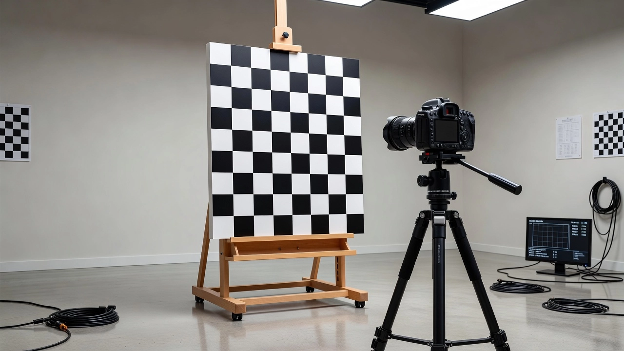
Geometric Registration
Each sensor has a unique optical axis and field of view. The geometric relationship between sensors — the boresight offset — must be calibrated. The boresight offset is a six-parameter transformation (three rotation angles and three translations) that defines how the thermal camera’s coordinate system relates to the RGB camera’s. This calibration is performed by imaging a target visible in both spectra (a heated checkerboard pattern for RGB-thermal calibration) and computing the transformation that aligns the two images.
For the DJI Zenmuse H20T, the boresight calibration aligns the 20 MP zoom camera, 12 MP wide-angle camera, and 640×512 thermal camera into a common reference frame, enabling the software to overlay thermal data on RGB imagery with pixel-level accuracy.
Payload Weight and Gimbal Capacity
Multi-sensor payloads are heavier than single sensors, pushing against the gimbal’s torque capacity. The H20T’s total payload weight is 829 g, requiring a gimbal with sufficient torque margin. Exceeding the rated payload capacity causes the gimbal to saturate its motors (run at maximum current without achieving the commanded position), resulting in horizon tilt, drift, and eventual motor overheating.
The gimbal is the enabling technology for drone-based infrastructure inspection. Without active stabilization, the vibration and motion of the drone would make every image unusable for measurement, and the inability to independently control camera orientation would prevent oblique inspection of vertical structures.
Pavement and Road Inspection
For road pavement condition assessment, the gimbal must maintain nadir orientation (pitch = -90°) throughout the entire flight mission with angular stability better than 0.05° RMS. The drone flies at 40-60 m altitude at 5-10 m/s, capturing imagery at 1-2 cm GSD. Crack widths as narrow as 0.3 mm must be detectable, requiring zero motion blur. The combination of gimbal stabilization (eliminating angular vibration), fast shutter speed (1/500-1/1000 second), and adequate lighting produces sharp images even at these speeds. Gimbal yaw lock mode is essential for corridor inspections — the camera maintains constant heading along the road axis, ensuring consistent image geometry for orthomosaic stitching.
Bridge Inspection
Bridge inspection requires both nadir imagery (bridge deck surface, overlay condition, crack mapping) and oblique imagery (girder sides, abutments, bearing assemblies, expansion joints). The gimbal enables a single flight to capture both perspectives: a nadir grid pass covers the deck, followed by oblique orbit passes around each substructure unit. For under-bridge inspection, specialized gimbals with pitch range extending to -135° can point the camera upward to capture soffit surfaces. The gimbal’s lock mode maintains camera heading on the bridge axis, preventing photogrammetric breaks at bridge ends.
For vertical infrastructure (telecommunications towers, power transmission towers, wind turbine towers, smokestacks), the gimbal is set to oblique pitch (30-60°) and the drone executes an orbit around the structure at constant radius and altitude. The gimbal’s point-of-interest (POI) tracking function automatically keeps the camera aimed at the structure’s center point as the drone orbits, ensuring every face of the structure is captured at the same oblique angle. For multi-segment structures (e.g., wind turbine towers with nacelle and blades), multiple orbits at different altitudes and pitch angles provide complete coverage.
Building Facade Inspection
Building facade inspection is the most demanding gimbal application. The drone must fly parallel to the wall at a constant standoff distance (typically 5-15 m), maintaining a consistent oblique angle while compensating for wind gusts, building-induced turbulence (the wind shear effect around corners), and the pilot’s imperfect manual control. The gimbal’s stabilization must reject both low-frequency position drift (the drone’s imperfect station-keeping) and high-frequency vibration (propulsion and wind). A stabilization accuracy of 0.01° RMS at 15 m distance translates to 2.6 mm of image displacement at the facade — sufficient for detecting cracks, spalling, and sealant failures.
Gimbal and Photogrammetry Quality
The gimbal’s performance directly determines the quality of the photogrammetric output — the orthomosaic, digital surface model (DSM), and 3D mesh derived from the inspection imagery.
Image Sharpness and Motion Blur
The most direct gimbal contribution to photogrammetry quality is image sharpness. Angular vibration during the shutter-open interval creates motion blur. The motion blur magnitude in pixels is:
For a 24 mm lens with 6 µm pixel size, a shutter speed of 1/250 second, and an angular vibration rate of 0.5°/s (typical for an unstabilized drone), the motion blur is:
Blur = (24 mm × 0.0087 rad/s × 0.004 s) / 0.006 mm = 0.14 pixels (acceptable)
A gimbal reducing vibration to 0.01°/s reduces this to 0.003 pixels — effectively zero. The gimbal enables slower shutter speeds (1/60 second instead of 1/500) while maintaining sharpness, allowing lower ISO settings and reducing image noise.
Camera Calibration Stability
The gimbal holds the camera in a fixed orientation during capture, preventing the camera calibration parameters from changing between images. Variations in camera pitch, roll, and yaw are known from the gimbal telemetry, providing initial orientation estimates to the photogrammetry software. This reduces the bundle adjustment solution space, speeds convergence, and improves the reliability of the calibration parameter estimation.
Georeferencing Accuracy
The gimbal’s encoder outputs are combined with the drone’s GNSS position to compute the camera’s position and orientation at the moment of capture — the exterior orientation (EO) parameters. The EO parameters are recorded in the image EXIF metadata as:
GPS coordinates (latitude, longitude, altitude) from the drone’s GNSS receiver
Yaw (compass heading) from the gimbal yaw encoder
Pitch and roll from the gimbal’s IMU/encoder fusion
The accuracy of these EO parameters determines the quality of direct georeferencing (photogrammetric processing without ground control points). RTK GNSS provides 1-3 cm position accuracy, and the gimbal encoder provides 0.01-0.1° angular accuracy. Combined, these enable direct georeferencing accuracy of 2-10 cm at 60-100 m altitude.
Impact on Point Cloud and Mesh Quality
The photogrammetric point cloud density and precision depend on the quality of the input imagery. Gimbal-stabilized images produce:
Higher tie point density: Sharp images enable feature matching algorithms to detect and match more points, increasing the photogrammetric point cloud density by 30-50% compared to blurred or geometrically inconsistent imagery.
Lower reprojection error: Consistent image geometry reduces the RMS reprojection error in bundle adjustment. A well-stabilized block typically achieves RMSE of 0.3-0.5 pixels, compared to 0.8-1.5 pixels for poorly stabilized imagery.
Fewer reconstruction failures: Consistent overlap and sharp imagery eliminate the reconstruction breaks and hole artifacts that plague missions with inadequate gimbal stabilization.
Summary
The gimbal is the single most important hardware component in drone-based infrastructure inspection after the camera itself. It bridges the gap between the dynamic, vibrating drone platform and the geometrically stable imaging geometry required for precise measurement. Key points:
A 3-axis gimbal stabilizing pitch, roll, and yaw is the minimum requirement for professional inspection work. 2-axis gimbals (pitch and roll only) cannot maintain consistent yaw heading.
Stabilization accuracy of 0.003-0.01° RMS is required for high-precision inspection work. Consumer gimbals at 0.02-0.05° are adequate for visual inspection but insufficient for sub-centimeter photogrammetry.
Nadir-oblique switching enabled by gimbal pitch articulation is essential for complete infrastructure inspection — nadir covers horizontal surfaces, oblique covers vertical surfaces, and the combination eliminates the dome effect in photogrammetry.
Gimbal calibration must be performed regularly (before each flight session at minimum) and correctly (on a level surface, with proper magnetic environment) to ensure accurate geotagging and stable stabilization.
Multi-sensor gimbals carrying RGB, thermal, and LiDAR payloads simultaneously are the standard for comprehensive inspection, but introduce additional calibration requirements for sensor boresight alignment and payload weight management.
Maintenance includes balancing the payload after any camera or accessory change, verifying vibration dampeners for wear (replace every 6-12 months in heavy use), and checking slip rings for electrical continuity. A properly maintained gimbal operating within its rated payload capacity will perform consistently across hundreds of flight hours.
Budget allocation for a drone inspection program should account for the gimbal as a separate investment from the drone and camera. A high-quality gimbal for a 2-3 kg payload system costs $3,000-8,000, while consumer-class gimbals are integral to sub-500 g drones. The gimbal cost is justified by the improvement in data quality and the reduction in re-flight rates.
Frequently Asked Questions
A gimbal actively stabilizes the camera against the drone's motion and vibration. It uses brushless motors, an inertial measurement unit (IMU), and PID control algorithms to continuously counteract pitch, roll, and yaw movements of the aircraft. This keeps the camera pointed precisely at the target, eliminating motion blur and ensuring geometrically consistent images for photogrammetry. Without a gimbal, drone vibrations of 0.5-2.0° amplitude would translate into 10-40 pixel motion blur at typical shutter speeds, making accurate measurements impossible.
A 2-axis gimbal stabilizes pitch and roll only, leaving yaw (compass heading) uncontrolled. This means the camera can rotate with the drone's heading changes, causing image orientation inconsistencies between overlapping photos. A 3-axis gimbal adds active yaw stabilization, keeping the camera locked in a constant compass direction regardless of the drone's yaw movements. For photogrammetry, the 3-axis configuration is essential because it maintains consistent image overlap geometry, eliminates orientation discontinuities between strips, and ensures the principal point remains stable across the entire block. Professional inspection platforms such as the DJI Zenmuse series, Sony UMC series, and Phase One iXM series all employ 3-axis stabilization.
Gimbal angular accuracy directly propagates into photogrammetric measurement error. A gimbal with ±0.02° angular deviation at a 100 m flight altitude produces a 3.5 cm lateral displacement of the camera's optical axis at the ground level. Inadequate stabilization creates inconsistent image overlap — if the gimbal allows 1° of unintended roll variation between adjacent images, the effective sidelap changes by approximately 1.7% of the swath width at 100 m altitude. For a typical 80% sidelap target, a 1° roll error reduces actual overlap to below the 60% minimum required for reliable feature matching, creating hole artifacts in the orthomosaic.
Gimbal calibration is the process of aligning the gimbal's internal reference frame with the camera's optical axis and the aircraft's body frame. It involves three procedures: (1) IMU calibration — leveling the accelerometer and gyroscope biases while the drone rests on a perfectly flat surface; (2) gimbal auto-calibration — the gimbal sweeps through its full pitch, roll, and yaw range to learn endpoint stops and center positions; (3) gimbal compass calibration — compensating for hard-iron and soft-iron magnetic interference that affects yaw accuracy. Calibration should be performed before every flight session, after hard landings, after firmware updates, when operating at a location with different magnetic declination, or when temperature changes exceed 15°C since the last calibration.
The gimbal's pitch axis controls the camera's tilt angle from nadir (straight down, 90° from horizontal) to oblique (typically 30-60° from vertical). For infrastructure inspection, this pitch articulation allows the same sensor to capture overhead surfaces (roofs, bridge decks, pavements) in nadir orientation and vertical surfaces (building facades, bridge girders, turbine towers, dam walls) in oblique orientation — all within a single flight mission. The gimbal maintains active stabilization at any commanded angle, so oblique images are equally sharp and geometrically consistent as nadir images. Modern flight planning software automatically sequences gimbal position changes between nadir grid passes and oblique orbit passes.
The dome effect (or bowl effect) is a systematic elevation error in photogrammetric models where the reconstructed surface appears domed or bowed. It arises from strong correlation between radial lens distortion parameters (especially k1) and elevation in nadir-only image blocks. The gimbal influences the dome effect through its ability to capture oblique images — the primary mitigation strategy. Research by Roncella and Forlani (Sensors, 2021) demonstrated that including oblique images captured at 20-45° off-nadir, comprising at least 10% of the block, reduces the dome effect from 0.1-0.5% of flight height to below 0.01%. The gimbal's pitch articulation makes this oblique capture practical without sacrificing stabilization quality.
Multi-sensor gimbals simultaneously house 2-3 different sensor types in a single stabilized platform. Common combinations include: RGB camera + thermal infrared camera (FLIR) for simultaneous visual and thermal inspection; RGB camera + LiDAR scanner for combined photogrammetry and laser scanning; RGB camera + multispectral camera for precision agriculture; and RGB camera + thermal camera + LiDAR for comprehensive infrastructure assessment. Each sensor requires independent calibration relative to the gimbal frame, and the combined payload weight must stay within the gimbal's rated torque capacity. The DJI Zenmuse H20 series, for example, carries a 20 MP zoom camera, a 12 MP wide-angle camera, a thermal camera (640×512), and a laser rangefinder in a single 829 g gimbal payload.
A drone gimbal consists of: (1) three brushless DC motors — one per axis (pitch, roll, yaw), providing direct-drive torque without gears to eliminate backlash; (2) an IMU (inertial measurement unit) containing a 3-axis gyroscope (angular rate sensor) and 3-axis accelerometer, operating at 1-8 kHz sampling rate; (3) absolute magnetic encoders or Hall-effect sensors on each axis for position feedback with resolution of 0.01-0.1°; (4) a dedicated microcontroller running the PID control loop at 1-10 kHz; (5) vibration dampeners (silicone rubber isolators or spring-damper assemblies) between the drone airframe and the gimbal mount; and (6) slip rings for uninterrupted electrical signal transmission through the yaw axis.
Gimbal dampening refers to both active (electronic) and passive (mechanical) vibration isolation. Passive dampening uses elastomeric isolators (typically silicone rubber or neoprene grommets) placed between the drone's airframe and the gimbal suspension. These isolators are tuned to cut off frequencies above 15-30 Hz, which is the dominant vibration band of multirotor drones. Active dampening is the gimbal's motor control loop itself — the IMU detects residual angular vibration at up to 8 kHz, and the PID controller commands the motors to cancel these motions in real time. The combined system achieves transmissibility of less than 0.05 (95% vibration reduction) in the 15-100 Hz range critical for image sharpness.
Gimbal drift is the slow angular deviation of the camera from the commanded orientation over time. It is caused by gyroscope bias drift (typically 0.1-1.0°/hour for MEMS gyroscopes), accelerometer bias drift, temperature effects on IMU sensors, and magnetic disturbances affecting the yaw reference. In high-end inspection gimbals, drift is managed through: (1) IMU temperature compensation models that subtract bias as a function of temperature; (2) periodic gyroscope bias re-estimation during straight-and-level flight segments; (3) magnetometer-aided yaw stabilization with declination lookup; and (4) in systems with RTK GNSS, yaw correction from dual-antenna heading. Well-compensated gimbals maintain angular drift below 0.1° per hour of operation.
The gimbal communicates with the flight controller via a dedicated serial protocol (typically CAN bus, UART, or PWM). The flight controller sends gimbal commands (target pitch, roll, yaw angles) and receives gimbal status data. The integration enables: (1) automated camera pointing during mission execution — the flight controller commands the gimbal to nadir during grid passes and oblique angles during orbit passes; (2) heading synchronization — the gimbal can operate in Follow mode (camera heading tracks drone heading), FPV mode (camera pitch and roll mirror the drone), or Lock mode (camera maintains fixed compass heading regardless of drone yaw); (3) GPS waypoint alignment — the gimbal autonomously points toward designated points of interest based on the drone's GPS position.
Key gimbal specifications for photogrammetry include: (1) angular stabilization accuracy — the residual angular error during stabilization, typically 0.01-0.05° for professional gimbals; (2) angular resolution — the smallest controllable angle increment, typically 0.01-0.1°; (3) controlled axis speed — maximum and minimum angular velocity (e.g., 0.01-30°/s for smooth point-of-interest tracking); (4) payload capacity — maximum sensor weight the gimbal can stabilize (e.g., 800 g to 3 kg depending on gimbal class); (5) vibration isolation bandwidth — the frequency range over which passive isolators are effective; (6) gimbal response bandwidth — the frequency at which the active control loop can track or reject disturbances (typically 10-50 Hz for consumer gimbals, 50-100 Hz for professional gimbals).
Consumer gimbals (e.g., DJI Zenmuse X5 series, standard mounts on DJI Phantom/Mavic) typically achieve 0.02-0.05° stabilization accuracy, carry 100-500 g payloads, use 2-3 kHz control loop rates, and lack payload customization. Industrial inspection gimbals (e.g., DJI Zenmuse H20T, Sony UMC-R10C, Phase One iXM-GS, Gremsy T3 series) achieve 0.003-0.01° stabilization accuracy, carry 500-3000 g payloads, use 5-10 kHz control loop rates, support hot-swappable multi-sensor payloads, include IP-rated weather sealing (IP43-IP67), and provide calibrated encoder feedback for geotagging accuracy. The industrial gimbal's tenfold improvement in stabilization accuracy translates directly to sharper images at longer focal lengths and higher measurement accuracy in photogrammetric processing.
Gimbal angles (pitch, roll, yaw) are recorded in image EXIF/XMP metadata alongside GPS coordinates and altitude. For DJI drones, the metadata follows the Camera and Gimbal Orientation tags in MAVLink Telemetry format, typically recorded at 10 Hz during flight. The yaw angle is relative to magnetic north (or true north when compass declination is applied), pitch is relative to the horizon (0° = level, -90° = straight down/nadir), and roll is relative to level flight (0° = level). These angles are essential for photogrammetry software to compute initial camera orientation estimates before bundle adjustment refinement. Inaccurate gimbal angles in metadata increase the risk of photogrammetric reconstruction failure, especially for oblique images and long, narrow corridor surveys typical of linear infrastructure inspection.
Precision Gimbal-Stabilized Inspection
Achieve sub-millimeter measurement accuracy from your drone inspection imagery. Our platform supports advanced gimbal calibration workflows and ensures consistent nadir-to-oblique image geometry for infrastructure assessment.
Drone-based infrared thermography mounts thermal cameras on UAVs to rapidly survey bridge decks and pavements for delamination, debonding, and moisture from the...
Automated drone inspection uses pre-programmed flight paths, computer vision, and AI analysis to survey infrastructure assets including runways, bridges, roads,...