Bridge Pier
A bridge pier is an intermediate vertical support structure between abutments that transfers superstructure loads to the foundation. Multi-column bents, wall pi...
28 min read
Bridges
Inspection
+3
Bridge girders are the primary horizontal load-carrying beams supporting the bridge deck, spanning between piers and abutments. Common types include steel I-girders, plate girders, prestressed concrete I-girders, box girders, and tub girders. Girder condition — including cracking, corrosion, section loss, fatigue, and prestress loss — is a key SNBI superstructure rating element. Covers girder types, distress modes, inspection methods, and load rating implications.
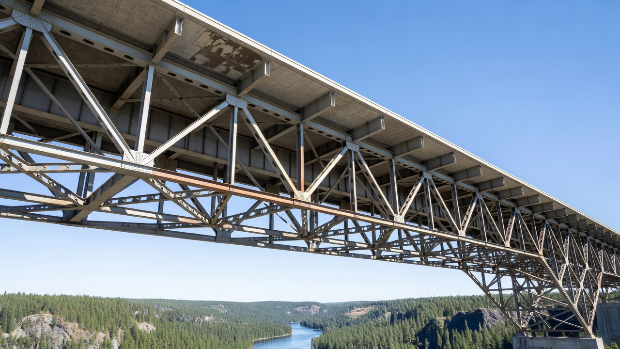
A bridge girder is the primary horizontal load-carrying member in a bridge superstructure. It spans between vertical supports — abutments at the bridge ends and piers at intermediate points — and directly supports the bridge deck. The girder resists bending moments (flexure) and shear forces induced by dead loads (self-weight of the girder, deck, wearing surface, utilities, barriers) and live loads (vehicular traffic, pedestrians). Girders transfer these loads through bearings to the substructure and ultimately to the foundation.
The structural function of a girder is defined by its resisting mechanism. In a simply supported girder, the top flange is in compression and the bottom flange is in tension under gravity loads, while the web resists shear. In continuous girders spanning over multiple piers, the bending moment reverses over the supports — the top flange is in tension and the bottom flange is in compression in the negative moment region over piers. This reversal of stresses is a critical consideration in both design and inspection because different fatigue-prone details and distress mechanisms govern in positive and negative moment zones.
The AASHTO LRFD Bridge Design Specifications classify girders as primary superstructure elements. The FHWA Bridge Inspector’s Reference Manual (BIRM) identifies girders as the controlling superstructure members for condition assessment. In the AASHTO Manual for Bridge Element Inspection (MBEI), girders are tracked as distinct element types with specific element numbers: Element 110 — Steel Open Girder/Beam, Element 111 — Steel Closed Girder/Box Girder, and Element 109 — Prestressed Concrete Girder. Each element is quantified in units of linear feet and assigned quantities in four condition states during inspection.
The span range of different girder types varies significantly. Rolled steel beams (W-shapes) are economical for spans up to approximately 30 m (100 ft). Welded plate girders extend the economical range to 60 m (200 ft) or more. Prestressed concrete AASHTO I-girders are used for spans from 15 m (50 ft) to approximately 45 m (150 ft), while bulb-tee sections reach 55 m (180 ft). Steel box girders and tub girders are used for spans from 30 m (100 ft) to over 90 m (300 ft) in curved and long-span applications. Concrete box girders, typically cast-in-place post-tensioned, are used for spans from 25 m (80 ft) to over 200 m (650 ft) in segmental construction.
Bridge girders are classified by material (steel, prestressed concrete, reinforced concrete) and cross-sectional shape (I-shape, box, tub, T-shape, bulb-tee). The following are the primary girder types used in modern highway bridges.
Steel I-Girder (Rolled Beam). The steel I-girder is fabricated from a standard rolled wide-flange (W-shape) section produced at steel mills. Rolled beams are available in depths up to approximately 1,100 mm (44 inches) and are limited by rolling mill capacities. Common grades include ASTM A709 Grade 50 (50 ksi yield strength) and Grade 50W (weathering steel). Rolled I-girders are the most economical option for short to moderate spans because they require no fabrication welding beyond connection plates and stiffeners. They are used in multi-girder systems with typical spacings of 1.8–3.7 m (6–12 ft) supporting a cast-in-place reinforced concrete deck acting compositely through shear connectors. The SNBI span type code for rolled steel beams is G02.
Steel Plate Girder (Welded I-Girder). When span and load demands exceed the capacity of rolled shapes, plate girders are fabricated by welding together steel plates — a web plate and two flange plates — in an I-shaped cross-section. Plate girders are built-up sections that can be optimized for specific design requirements, including variable depth and variable flange thickness. The web depth can be as large as 3 m (10 ft) or more, limited only by transportation constraints and lateral-torsional buckling considerations. Flange plates can be up to 100 mm (4 in) thick. Plate girders commonly use transverse stiffeners welded to the web to prevent web buckling and bearing stiffeners at support points to transfer concentrated reactions. Intermediate transverse stiffeners may be designed as bearing stiffeners or as intermediate stiffeners for shear resistance. The AASHTO LRFD specifications require that plate girders with web slenderness ratios (D/tw) exceeding certain limits have transverse stiffeners. Longitudinal stiffeners are sometimes added for very deep girders to control flexural buckling of the compression flange. The SNBI span type code for built-up welded plate girders is G01.
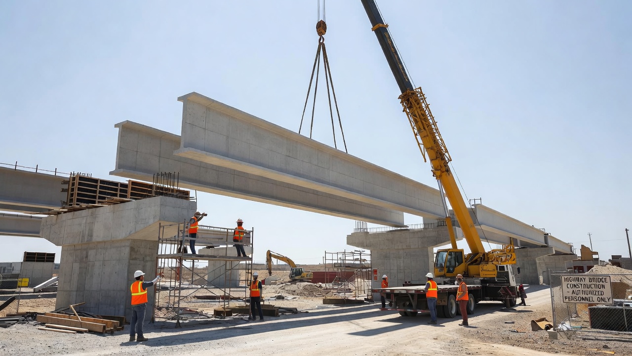
Prestressed Concrete I-Girder. Precast, prestressed concrete I-girders are among the most common bridge elements in the United States. The AASHTO standard I-girder shapes — Types I through VI — are defined in the AASHTO LRFD Bridge Design Specifications with increasing depths from 710 mm (28 in) for Type I to 1,830 mm (72 in) for Type VI. The PCI bulb-tee sections (BT-54, BT-63, BT-72) offer improved efficiency with a wider top flange that increases the compression area and provides a larger deck casting surface. Bulb-tee sections have depths of 1,370 mm (54 in), 1,600 mm (63 in), and 1,830 mm (72 in). Prestressing is provided by seven-wire low-relaxation strands (Grade 270 or Grade 250) with diameters of 12.7 mm (0.5 in) or 15.2 mm (0.6 in). Strands are tensioned to approximately 75% of their ultimate tensile strength before concrete placement (pre-tensioning). The prestressing force is transferred to the concrete by bond after the concrete reaches a specified release strength, typically 5,000–6,000 psi. Debonded strands are used at girder ends to control tensile stresses at release. Harped strands (depressed at midspan) optimize prestress distribution along the girder length. The SNBI span material code for prestressed concrete is C06 and span type code is S05.
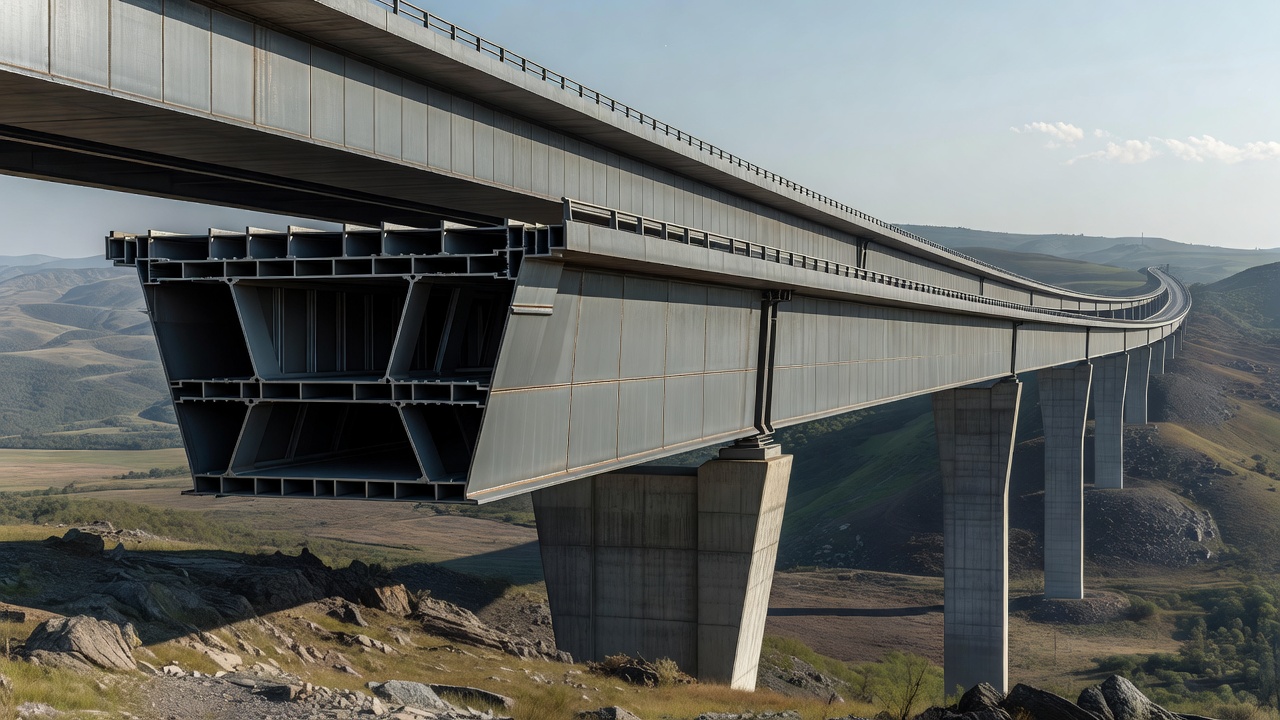
Steel Box Girder (Closed Box). A steel box girder is a closed cross-section typically consisting of two or three webs with top and bottom flanges, forming a rectangular or trapezoidal box that is torsionally stiff. Closed box girders are used for curved bridges where torsional loads from curvature are significant, for long-span bridges where aerodynamic stability matters, and for bridges with tight vertical clearance constraints where the shallower structural depth of a closed box is advantageous. Box girders are fabricated from steel plate with welded joints, and the top flange typically acts compositely with a cast-in-place concrete deck. The enclosed interior of a box girder requires access hatches, ventilation, and dehumidification systems to prevent corrosion, and inspections require confined space entry protocols. The SNBI span type code for steel box girders is G04.
Steel Tub Girder (Trapezoidal Box). The steel tub girder — also called a trapezoidal box girder — is an open-topped trapezoidal cross-section that becomes a closed section when the concrete deck is placed. Tub girders combine the torsional efficiency of a box with the constructability advantages of an I-girder. The bottom flange is trapezoidal (wider at the bottom), with two inclined webs. The webs are typically stiffened with longitudinal and transverse stiffeners. Tub girders are selected for their aesthetic appearance — the smooth, uninterrupted cross-section is visually preferred — and for their excellent torsional stiffness for curved bridges. Press-brake-formed tub girders are a specialized variant fabricated by cold-bending steel plate into shallow tub shapes, typically used for shorter spans (15–30 m). The FHWA recognizes tub girders as an efficient solution for moderate-span curved bridges, offering significant advantages in span range, stiffness, and durability. The AISC Steel Bridge Design Handbook provides comprehensive design guidance for composite steel tub girder bridges.
Girder Type Comparison Table.
| Girder Type | Typical Span Range | Material | Cross-Section | SNBI Code | Key Inspection Focus |
|---|---|---|---|---|---|
| Rolled Steel I-Beam | 10–30 m (30–100 ft) | Steel (A709) | I-shape, rolled | G02 | Corrosion at ends, fatigue at connections |
| Welded Plate Girder | 20–60 m (65–200 ft) | Steel (A709) | I-shape, welded | G01 | Weld quality, stiffener cracks, corrosion |
| Prestressed Concrete I-Girder | 15–55 m (50–180 ft) | Prestressed concrete | I-shape or bulb-tee | S05 | Cracking, spalling, strand corrosion |
| Steel Box Girder | 30–90 m (100–300 ft) | Steel (A709) | Rectangular closed box | G04 | Internal corrosion, confined space entry |
| Steel Tub Girder | 30–90 m (100–300 ft) | Steel (A709) | Trapezoidal open box | G05 | Web stiffeners, flange corrosion |
| Press-Brake Tub Girder | 15–30 m (50–100 ft) | Steel (galvanized) | Shallow trapezoidal | G05 | Galvanizing condition, cold-bend cracks |
| Concrete Box Girder | 25–200 m (80–650 ft) | Post-tensioned concrete | Rectangular closed box | S07 | Tendon condition, web cracking, drainage |
Steel girders deteriorate through several distinct mechanisms that reduce structural capacity. Each distress mode has characteristic visual indicators, measurement parameters, and severity classifications used in inspection.
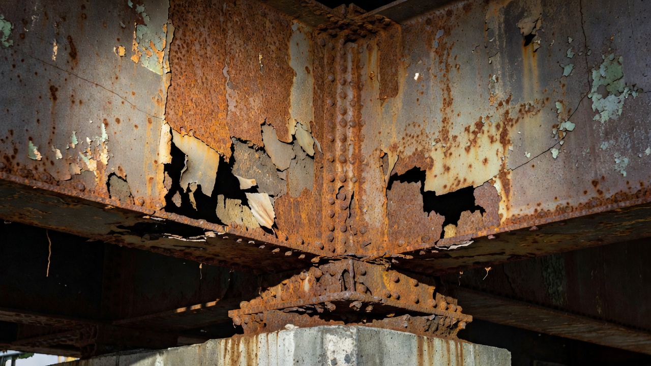
Corrosion. Corrosion is the most prevalent distress mode in steel bridge girders. It is an electrochemical process in which iron in the steel oxidizes to form iron oxides (rust) in the presence of oxygen and moisture. Section loss from corrosion reduces the effective load-carrying cross-section. The critical locations for girder corrosion are bearing zones where water and deicing chemicals accumulate on the bottom flange and web, deck joint leakage areas where joint sealant failure allows chloride-laden runoff to drip onto the girder below, splash zones near roadway drainage where vehicle spray deposits moisture and salts, and pockets where debris accumulates against the girder, trapping moisture. Corrosion is classified as surface corrosion (minor, cosmetic, less than 10% section loss), section loss corrosion (10–30% section loss, measurable by ultrasonic thickness gauging), and severe section loss (greater than 30% section loss, which may include holes through the web or flange). The FHWA Scoring Guide for Steel Bridge Corrosion provides a 5-category classification from Category 1 (no corrosion) to Category 5 (holes in girder). Weathering steel (A709 Grade 50W) develops a protective patina layer that reduces corrosion rates, but can develop accelerated corrosion (delamination of patina) in environments with persistent moisture, chloride exposure, or poor drainage.
Fatigue Cracking. Fatigue cracking is the most critical steel girder distress because it can lead to sudden, catastrophic fracture. Fatigue cracks initiate at stress concentration points where cyclic tensile stresses exceed the material’s fatigue resistance. AASHTO categorizes fatigue details into categories A through E’ based on the detail’s fatigue resistance, with Category A being the most resistant (plain rolled steel) and Category E’ being the least resistant (thick cover plates with transverse end welds). The most fatigue-prone locations on steel girders include: weld toes of transverse stiffeners, weld terminations at cope holes, cover plate ends (Category E for flange thickness less than 20 mm, Category E’ for thickness greater than 20 mm), connection plates for cross-frames and diaphragms, block cutouts at girder ends, and groove welds in flange splices. Fatigue cracks typically initiate at the weld toe and propagate through the base metal perpendicular to the principal tensile stress. Distortion-induced fatigue — caused by out-of-plane bending of girder webs due to differential deflection between adjacent girders at cross-frame connections — is a significant concern in bridges with skewed supports and flexible webs. The FHWA-NHI-16-016 manual on fatigue and fracture in steel bridges provides comprehensive guidance on identifying, inspecting, and repairing fatigue cracks.
Section Loss. Section loss in steel girders results from corrosion, mechanical abrasion, or impact damage. The loss of cross-sectional area directly reduces the section modulus (S = I / c, where I is the moment of inertia and c is the distance from the neutral axis to the extreme fiber), which governs flexural capacity. Section loss in the tension flange is most critical because the full flange area contributes to the tensile force couple. Section loss in the compression flange may induce local buckling at reduced stress levels. Section loss in the web reduces shear capacity and can lead to shear buckling. Measured section loss is expressed as a percentage of the original member dimensions. Ultrasonic thickness measurements at the most corroded cross-section provide the remaining thickness, which is used in load rating calculations per AASHTO MBE Section 6.
Impact Damage. Impact damage occurs when over-height vehicles strike the bottom flange of girders at low vertical clearance locations. Impact can cause bent flanges, buckled webs, cracked welds, misalignment, and in severe cases, fracture of girder components. Impact damage is most common at railroad underpasses, low-clearance roadways, and bridge approaches where pavement settlement has reduced the effective vertical clearance. Inspection of impacted girders requires dimensional measurements to quantify flange distortion, web flatness checks for buckling, and NDT (dye penetrant or magnetic particle testing) of welds in the impact zone for cracking. Impact damage may require immediate traffic restriction pending evaluation.
Prestressed concrete girders develop distress through distinct mechanisms related to concrete material degradation, prestress loss, and reinforcement corrosion.
Flexural Cracking. Flexural cracks in prestressed concrete girders are vertical or near-vertical cracks that initiate at the bottom (tension) flange in the positive moment region (midspan) and propagate upward through the web. Under service loads, properly designed prestressed girders should remain uncracked (Class U per AASHTO) or have limited crack widths (Class C). Crack widths exceeding 0.010–0.014 inches (0.25–0.35 mm) in aggressive environments indicate either overload (live load exceeding design), prestress loss (reduced compression from relaxation, creep, and shrinkage), or section loss (spalling reducing effective section). Flexural cracks provide direct pathways for chlorides and moisture to reach the prestressing strands, initiating corrosion. Crack spacing and width should be measured and documented, and comparison with previous inspection records identifies progression.
Shear Cracking. Shear cracks appear near girder ends where shear stresses are highest. They are diagonal cracks oriented at approximately 45° to the longitudinal axis, typically in the web region. Shear cracking indicates that the principal tensile stress in the web exceeds the concrete tensile strength. In prestressed girders, the vertical component of the inclined prestressing strands (harped strands) contributes to shear resistance. Web cracking that intersects the path of harped strands is particularly concerning because it may indicate web splitting from the radial component of the prestressing force. Diagonal cracks near supports extending into the bottom flange at the bearing zone can reduce shear transfer capacity. The AASHTO MBE provides criteria for evaluating shear capacity in cracked prestressed girders.
Spalling and Delamination. Spalling is the loss of concrete cover over reinforcing steel or prestressing strands. It occurs when corrosion of embedded steel produces expansive rust products that exert internal tensile stresses on the surrounding concrete, exceeding the tensile strength and causing the cover concrete to detach. Spalling at girder ends exposes prestressing strands to environmental attack. Corrosion-induced spalling at strand locations is a critical condition because it indicates active strand corrosion. Delamination (planar separation parallel to the surface) may precede spalling and is detected by chain drag or hammer sounding. Spalling reduces the cross-sectional area available to resist compressive and tensile stresses and eliminates the cover that protects strands from further corrosion.
Prestress Loss and Strand Corrosion. Prestress loss in pretensioned concrete girders occurs through three mechanisms: elastic shortening (immediate upon transfer), concrete creep (time-dependent deformation under sustained prestress), concrete shrinkage (time-dependent volume change), and steel relaxation (reduction of strand stress under constant strain). Long-term prestress losses typically range from 15% to 25% of the initial prestress. Strand corrosion is the most dangerous condition because a single strand fracture reduces the prestressing force by the strand’s contribution (typically 15–20 kips per strand for 0.6-inch strands). Hydrogen embrittlement is a failure mechanism in high-strength prestressing steel where atomic hydrogen diffuses into the steel lattice, reducing ductility and causing brittle fracture at stresses below the yield strength. Chlorides from deicing salts are the primary cause of strand corrosion in bridge girders. Inspection findings of rust staining on girder surfaces, longitudinal cracking along strand paths, or exposed corroded strands constitute critical findings requiring immediate evaluation and potential load restriction.
The Specifications for the National Bridge Inventory (SNBI), published by FHWA in March 2022 (FHWA-HIF-22-017), establishes the data reporting requirements for all highway bridges open to public traffic in the United States. Girder condition is reported through the Superstructure Condition Rating (data item B.C.02) and element-level condition data.
Superstructure Condition Rating (B.C.02) uses a 0-to-9 coding scale. The rating is component-based, meaning it describes the condition of the superstructure as a whole, considering all primary members. Per the SNBI Appendix C rating guidance, the superstructure condition rating codes are defined as follows:
| Code | Condition | Description |
|---|---|---|
| 9 | Excellent | No noticeable or noteworthy deficiencies |
| 8 | Very Good | Minor deterioration only |
| 7 | Good | Minor section loss, cracking, or spalling |
| 6 | Satisfactory | Moderate deterioration, but structural capacity not affected |
| 5 | Fair | Minor section loss, cracking, or spalling affecting structural capacity |
| 4 | Poor | Advanced section loss, deterioration, or cracking |
| 3 | Serious | Loss of section, deterioration, or cracking seriously affecting capacity |
| 2 | Critical | Advanced deterioration affecting structural capacity — close monitoring required |
| 1 | Imminent Failure | Critical condition — bridge should be closed |
| 0 | Failed | Out of service |
The SNBI also requires element-level data (data set B.E) for National Highway System (NHS) bridges. Each element is reported in four condition states: Condition State 1 (CS 1) — Protected/good, Condition State 2 (CS 2) — Minor deterioration/fair, Condition State 3 (CS 3) — Advanced deterioration/poor, Condition State 4 (CS 4) — Severe deterioration requiring action. For steel open girders (Element 110), CS 1 describes no corrosion or fatigue; CS 2 describes surface corrosion or minor pitting; CS 3 describes section loss up to 10% or fatigue cracks less than 2 inches; CS 4 describes section loss exceeding 10% or fatigue cracks exceeding 2 inches.
The example data set in the SNBI Appendix A for Bridge Number 15558X shows a Superstructure Condition Rating of 5 (Fair) with a Bridge Bearings Condition Rating of 4 (Poor) and a Bridge Joints Condition Rating of 2 (Critical) . These component ratings together provide a comprehensive picture of superstructure condition, with girder condition being the primary factor in the superstructure rating.
Bridge girder inspection follows the requirements established in the National Bridge Inspection Standards (NBIS) , the AASHTO Manual for Bridge Evaluation (MBE) , and the FHWA Bridge Inspector’s Reference Manual (BIRM) . Inspection of girders is classified as either routine inspection (at regular intervals, typically 12–24 months), in-depth inspection (hands-on, typically requiring access equipment), fracture-critical inspection (for tension members whose failure would cause bridge collapse), or special inspection (triggered by damage or deterioration).
Visual Inspection. Visual inspection is the primary inspection method for all girder types. The inspector examines the full length of each girder line, documenting all observable distress. For steel girders, the inspector evaluates corrosion extent and severity, fatigue cracks at welded connections, bolt condition at field splices, paint system condition (ASTM D610 rust grade), and impact damage. For concrete girders, the inspector evaluates crack width, length, and pattern; spall dimensions and depth; exposed strand condition; rust staining; and efflorescence. The inspection is documented on standard bridge inspection forms (or electronic data collection systems) that record each element’s quantity in each condition state per AASHTO MBEI element definitions. Hands-on inspection within arm’s reach of all critical details is required for fracture-critical members (FCMs). Access for visual inspection may require under-bridge inspection vehicles (snooper trucks), ladders, scaffolding, or boat access for water crossings.
Non-Destructive Testing (NDT). NDT methods are applied when visual inspection identifies conditions requiring further evaluation. The FHWA and AASHTO specify NDT methods for steel and concrete girders. For steel girders, the primary NDT methods are ultrasonic testing (UT) for detecting internal cracks in welds and base metal, magnetic particle testing (MT) for detecting surface and near-surface cracks in ferromagnetic steel, dye penetrant testing (PT) for detecting surface-breaking cracks, ultrasonic thickness gauging for measuring remaining flange and web thickness in corroded areas, and radiographic testing (RT) for weld inspection where access precludes UT. For concrete girders, methods include ultrasonic pulse velocity (UPV) for detecting internal voids and assessing concrete quality, impact-echo testing for detecting delamination and voids in tendon ducts, ground-penetrating radar (GPR) for locating embedded strands and detecting moisture intrusion, and half-cell potential mapping for assessing corrosion activity of embedded steel. The FHWA Steel Bridge Testing Program has evaluated NDE technologies for fatigue crack detection, establishing probability of detection (POD) curves for various methods.
Drone Inspection. Unmanned aerial vehicles (UAVs or drones) are increasingly used for girder inspection, particularly for high-clearance bridges over waterways, deep valleys, or traffic where access with snooper trucks is difficult or dangerous. Drones equipped with high-resolution cameras (20+ megapixels), optical zoom lenses (30x or greater) , and lighting systems can capture detailed imagery of girder bottom flanges, webs, and connections from all angles. LiDAR-equipped drones can create 3D point cloud models of the superstructure for dimensional measurements and deformation detection. Thermal imaging cameras on drones can detect moisture intrusion, delamination, and hidden corrosion. The SNBI includes B.IE.12 Inspection Equipment with code I3 for “Drone or Unmanned Aerial Vehicle (UAV)” used during inspection. Drone inspection data can be integrated into TarmacView’s digital twin platform for spatial registration of distress locations and change detection over time.

Fatigue cracking in steel bridge girders is governed by the AASHTO fatigue design categories defined in AASHTO LRFD Bridge Design Specifications Article 6.6.1. The categories classify welded and bolted details based on fatigue test data, assigning a constant-amplitude fatigue threshold (CAFL) for each category. The categories from highest to lowest fatigue resistance are:
| Category | CAFL (ksi) | Typical Details |
|---|---|---|
| A | 24 | Plain rolled steel, base metal away from welds |
| B | 16 | Welded beams with continuous longitudinal welds, flame-cut edges |
| B' | 12 | Full-penetration groove welds with backing bars removed |
| C | 10 | Transverse stiffener-to-flange welds, welded connections with toe |
| C' | 12 | Full-penetration groove welds with backing bars in place |
| D | 7 | Longitudinal fillet welds, welded cover plates less than 20 mm thick |
| E | 4.5 | Cover plates with transverse end welds, thickness less than 20 mm |
| E' | 2.6 | Cover plates with transverse end welds, thickness > 20 mm |
Fracture-critical members (FCMs) are steel tension members whose failure would cause the bridge to collapse. For steel girder bridges, the typical FCMs include two-girder systems (each girder is FCM), tied arches, and truss tension members. FCMs require hands-on inspection at intervals specified in the bridge’s FCM inspection plan. The SNBI reports whether fracture-critical inspection is required through B.IR.01 — NSTM Inspection Required (non-redundant steel tension member).
Distortion-induced fatigue at web-gap regions of cross-frame connections is a widespread problem in steel multi-girder bridges. When differential deflection occurs between adjacent girders, the cross-frame forces cause out-of-plane bending of the girder web in the small gap between the connection plate weld termination and the flange weld. This out-of-plane distortion generates secondary stresses that can cause fatigue cracking at the weld toe. AASHTO now requires that connection plates be welded directly to both flanges (or provide positive connection) to eliminate web-gap distortion. Inspection of existing bridges should focus on these connection plate-to-web welds for signs of distortion-induced cracking.
Bridge bearings are the interface between girders and substructure units. They fulfill three functions: transmitting vertical loads from the superstructure to the substructure, allowing rotation from dead load and live load deflection, and permitting horizontal movement from thermal expansion and contraction. The SNBI reports Bridge Bearings Condition Rating (B.C.07) using the same 0-to-9 coding scale.
Bearing types used with girders include elastomeric bearings (plain neoprene pads or laminated neoprene with steel plates), rocker bearings (steel rockers that tilt to accommodate longitudinal movement), roller bearings (single or multiple steel rollers), sliding plate bearings (PTFE on stainless steel for low friction), pot bearings (elastomeric pad confined in a steel cylinder), mechanical bearings (pinned or fixed), and high-load multi-rotational bearings.
Bearing distress modes include corrosion of steel bearing components (rocker arms, rollers, masonry plates, sole plates), freezing (loss of movement capability due to corrosion or debris accumulation), misalignment (rocker tilt exceeding design limits, typically 10°), elastomer deterioration (cracking, splitting, extrusion, or loss of elastomeric bearing pads), anchor bolt failure (sheared, corroded, or missing anchor bolts), masonry plate corrosion at the interface with the bearing seat, and sole plate connection failure (welded or bolted connection to girder bottom flange).
The AASHTO Manual for Bridge Element Inspection tracks bearings as a separate element (Element 310 — Elastomeric Bearing, Element 311 — Movable Bearing, Element 312 — Enclosed/Concealed Bearing, Element 313 — Fixed Bearing, Element 314 — Pot Bearing). Bearing condition directly affects girder load transfer. A frozen expansion bearing induces thermal forces in the girders that were not accounted for in design. A failed bearing at a support creates a gap between the girder and the bearing seat, redistributing reactions to adjacent supports. The BIRM provides detailed inspection checklists for each bearing type.
Girder deterioration directly reduces bridge load rating — the ratio of structural capacity to applied loads. The load rating factor (RF) is calculated per AASHTO MBE Section 6 as:
RF = (C - A1 × D) / (A2 × L × (1 + I))
Where C is capacity, A1 is dead load factor, D is dead load effect, A2 is live load factor, L is live load effect, and I is impact factor. Deterioration reduces the capacity term C, which reduces the RF.
For steel girders, the flexural capacity is M_n = F_y × S_x (at yield) or M_n = M_p (plastic moment, limited by lateral-torsional buckling). Section loss reduces the elastic section modulus (S_x) and plastic section modulus (Z_x). The remaining capacity is calculated using the measured section properties at the most deteriorated cross-section. For example, a 15% reduction in bottom flange area due to corrosion reduces the section modulus by approximately 10–15%, which reduces the RF by a proportional amount. The girder’s shear capacity V_n = 0.58 × F_y × D × t_w × C (where C accounts for web buckling). Web section loss directly reduces the web thickness, reducing shear capacity proportionally.
For prestressed concrete girders, the flexural capacity at the service limit state is governed by permissible tensile stresses. Prestress loss increases the net tensile stress under live load, and if tensile stress exceeds the allowable limit (typically 0.0948√f’c for Class C members), cracking occurs. At the strength limit state, strand corrosion that reduces the strand area reduces the ultimate moment capacity. Loss of one strand in a girder containing 40 strands reduces capacity by approximately 2.5%. However, loss of multiple strands or strands in the same row can reduce capacity more significantly due to the loss of prestress force distribution.
The SNBI Section 5 requires reporting of Inventory Load Rating Factor (B.LR.05), Operating Load Rating Factor (B.LR.06), and Controlling Legal Load Rating Factor (B.LR.07) . When the Operating Rating falls below 1.0, the bridge must be load posted with weight restrictions per the state’s legal load configuration (B.EP.01). The SNBI example data set for Bridge 15558X shows an Inventory Load Rating Factor of 0.30 and an Operating Load Rating Factor of 0.50 with posting values ranging from 15 to 30 tons depending on the legal load configuration.
The AASHTO MBE Section 6 provides specific procedures for load rating deteriorated girders. For steel girders, a remaining thickness survey using ultrasonic thickness gauging at 5-ft intervals along the full girder length establishes the minimum remaining section. For concrete girders, a detailed crack survey documenting crack width, length, spacing, and location combined with a strand survey at spalled areas establishes the effective prestress loss. The load rating engineer uses this field data to compute a deteriorated load rating, which may result in weight posting or the requirement for bridge strengthening or replacement.
Bridge girders are the primary load-carrying elements of the superstructure, available in multiple configurations — steel I-girders, welded plate girders, prestressed concrete I-girders (AASHTO and bulb-tee sections), steel box girders, and steel tub girders. Each type has characteristic distress modes: steel girders suffer corrosion (particularly at bearing locations and deck joints), fatigue cracking (at welded details governed by AASHTO categories A through E’), section loss, and impact damage; concrete girders develop flexural and shear cracking, spalling from strand corrosion, and prestress loss from long-term material effects. The SNBI evaluates girder condition through the Superstructure Condition Rating (B.C.02) on a 0-to-9 scale and through element-level condition state quantities. Inspection methods include visual inspection (the primary method), NDT (UT, MT, PT, UPV, impact-echo), and drone-based inspection for high-clearance bridges. Girder deterioration directly reduces load rating values through section loss and prestress loss, which may require load posting to ensure bridge safety. Understanding girder types, distress mechanisms, and inspection requirements is essential for bridge owners, inspectors, and engineers responsible for maintaining the safety and serviceability of the highway bridge inventory.
TarmacView provides expert bridge inspection services including visual inspection, drone-based superstructure evaluation, and NDT assessment of steel and concrete girders. Contact our team to schedule an inspection.
A bridge pier is an intermediate vertical support structure between abutments that transfers superstructure loads to the foundation. Multi-column bents, wall pi...
Bridge bearings are critical load-transfer devices at abutments and piers that transmit superstructure forces to the substructure while accommodating thermal mo...
A box girder is a hollow, closed-section bridge girder of steel or concrete that provides high torsional stiffness and efficiency for curved or long-span bridge...