Grout Pour — Cementitious Grouting for Concrete Repair
Cementitious grouting uses fluid cement-based mixtures poured or pumped to fill cracks, voids, or spaces in concrete — including tendon duct grouting, crack injection, under-sealing slabs, and filling honeycomb. Covers grout types (neat cement; sanded; expanding), placement methods (gravity; pressure; vacuum), and inspection for complete fill and bond.
Definition of Grout Pour in Cementitious Grouting
A grout pour is the controlled placement of a fluid cementitious mixture — comprising portland cement, water, and optionally fine aggregate or chemical admixtures — into a defined cavity, crack, void, duct, or space between existing concrete and substrate, with the purpose of filling that space completely, bonding to the surrounding surfaces, and restoring structural continuity, load transfer, or corrosion protection. The term “grout pour” is used across concrete construction, repair, and maintenance to distinguish the act of placing grout from the material itself (grout) and from the broader process (grouting).
Cementitious grouting is governed by multiple international and national standards. The FHWA Post-Tensioning Tendon Installation and Grouting Manual (FHWA-NHI-13-026) provides comprehensive guidance for grouting of post-tensioning tendons in bridges. The FAA Advisory Circular 150/5370-10H (Standard Specifications for Construction of Airports) references grout for airport pavement repairs, base course stabilization, and anchor installations. The ASTM C476 (Standard Specification for Grout for Masonry) defines fine and coarse grout classifications, and ACI 351.1R (Grouting for Equipment Baseplates) covers precision grouting applications.
The fundamental distinction between a grout pour and concrete placement is the material consistency and purpose. Grout is designed to be fluid enough to flow into narrow spaces under its own weight or moderate pressure, while structural concrete is designed to be placed in forms at a stiffer consistency. Grout typically contains only fine aggregate (sand passing a No. 4 sieve, maximum 4.75 mm) or no aggregate at all, while concrete contains coarse aggregate up to 20 mm or larger. Grout is used for specialized filling, bonding, and repair functions; concrete is used for primary structural elements.
The grout pour must be executed as a continuous operation until the void is completely filled. Interruptions can leave cold joints, voids, or incomplete fill. For large volume grout pours — such as under-slab grouting for pavement undersealing or large honeycomb repairs — multiple injection points are used to ensure complete coverage. For precision applications such as tendon duct grouting, the pour is monitored by observing grout return at outlet ports.
Types of Cementitious Grout
Cementitious grouts are classified by composition into three principal types: neat cement grout, sanded cement grout, and expanding cement grout. Each type has distinct rheological properties, strength characteristics, and application domains.
Neat Cement Grout
Neat cement grout consists of portland cement and water only, with no fine aggregate. The water-cement ratio (w/c) typically ranges from 0.35 to 0.50 by weight, though ratios as low as 0.30 may be used for specialized applications requiring maximum strength and minimum shrinkage. The w/c ratio is the single most important determinant of neat cement grout properties.
Property
Typical Range
Test Method
Water-cement ratio
0.35–0.50
Calculated from batch weights
Compressive strength (28-day)
30–55 MPa
ASTM C109 (50 mm cubes)
Flow cone efflux time
20–60 seconds
ASTM C939 (flow cone method)
Bleeding (24 hours)
0.5–4.0% by volume
ASTM C940
Initial setting time
2–6 hours
ASTM C191 (Vicat needle)
Final setting time
4–10 hours
ASTM C191 (Vicat needle)
Shrinkage (28-day drying)
2000–4000 microstrain
ASTM C157
Maximum crack penetration
0.5–1.0 mm
—
The compressive strength of neat cement grout decreases rapidly with increasing w/c ratio. At w/c = 0.35, 28-day strengths of 50 to 55 MPa are achievable. At w/c = 0.50, strength drops to approximately 25 to 35 MPa. The relationship follows the same water-cement ratio law that governs concrete strength (Abram’s Law), though with a steeper slope because there is no aggregate to contribute mechanical strength.
Neat cement grout is used for crack injection (non-structural) in concrete elements where the crack width is 0.5 to 5.0 mm and where full structural continuity is not required. The FHWA notes that “neat cement grout has been used extensively for filling cracks, ducts around post-tensioning tendons, and small voids” because its fluidity allows penetration into narrow openings. For post-tensioning tendon duct grouting, neat cement grout or a fine sanded grout (with sand passing a No. 16 sieve) is used to ensure complete filling of the interstitial spaces between individual strands within the duct.
A critical limitation of neat cement grout is bleeding — the separation of excess mixing water that rises to the surface after placement while the cement particles settle. Bleeding creates water voids at the top of horizontal or inclined cavities, compromising fill completeness and bond. The ASTM C940 test measures bleeding over a 3-hour period. Acceptable bleeding for post-tensioning grout is less than 2 percent by volume after 3 hours, with reabsorption of bleed water within 24 hours.
Sanded Cement Grout
Sanded cement grout incorporates fine aggregate (sand) in addition to cement and water, producing a material with improved dimensional stability, reduced shrinkage, higher yield, and better mechanical properties in thicker sections. The sand must pass a No. 16 sieve (1.18 mm) for most grouting applications, and may be up to No. 4 sieve (4.75 mm) for coarse grout applications such as masonry grouting (ASTM C476).
The sand-to-cement ratio by weight ranges from 0.5:1 to 3:1, with 2:1 being the most common for general-purpose grouting. The water-cement ratio is typically 0.45 to 0.55, though additional water may be required to achieve the desired fluidity with higher sand contents. The flow cone efflux time for sanded grout is typically 30 to 60 seconds (ASTM C939), somewhat higher than neat cement grout due to the sand content.
The advantages of sanded grout over neat cement grout include:
Reduced shrinkage — The sand skeleton restrains drying shrinkage. A 2:1 sand-cement grout has approximately 50 percent less drying shrinkage than neat cement grout, reducing the risk of debonding at the grout-concrete interface.
Lower heat of hydration — The sand dilutes the cement content per unit volume, reducing the peak temperature rise during hydration. This is important for pours exceeding 100 mm thickness where thermal cracking is a concern.
Higher yield — One metric ton of cement produces approximately 0.6 m³ of neat cement grout but 1.2 to 1.5 m³ of 2:1 sanded grout, reducing material cost per unit volume.
Better mechanical properties — The sand particles provide mechanical interlock and improve the modulus of elasticity, shear strength, and bond to rough surfaces.
Sanded grout is used for:
Filling larger cracks exceeding 3 mm width where sand particles can enter the opening
Honeycomb repair in concrete — filling surface and near-surface voids left by inadequate consolidation during concrete placement
Under-slab grouting (slabjacking, mudjacking) — pumping a sanded grout beneath settled concrete slabs to restore support and elevation
Anchor and dowel grouting — filling the annular space between a steel anchor or dowel bar and the surrounding concrete or rock
Baseplate grouting — filling the gap between a steel baseplate and the concrete foundation for structural equipment, bridge bearings, and columns
The maximum aggregate size in sanded grout must be no larger than one-third the minimum opening dimension to prevent particle bridging. For a 10 mm crack, sand passing a No. 16 sieve (1.18 mm) is acceptable. For honeycomb repair where the void opening is 25 mm or larger, sand passing a No. 8 sieve (2.36 mm) or No. 4 sieve (4.75 mm) may be used.
Expanding Cementitious Grout
Expanding cementitious grout contains admixtures that produce a controlled expansion in the plastic state, typically 0.5 to 4.0 percent linear expansion, to compensate for settlement and drying shrinkage. The expansion ensures that the grout maintains intimate contact with the surrounding surfaces after setting, providing complete fill and bond.
The most common expanding agent is aluminum powder, added at approximately 0.005 to 0.05 percent by weight of cement. The aluminum powder reacts with the alkaline hydroxide ions (OH⁻) in the cement pore water to produce microscopic hydrogen gas bubbles:
The FHWA Post-Tensioning Tendon Installation and Grouting Manual (FHWA-NHI-13-026) specifies that grout for post-tensioning tendons must have an expansion of 0 to 10 percent while in the plastic state to compensate for bleed water settlement and plastic shrinkage. The expansion must occur before the grout sets (typically within 30 to 60 minutes of mixing) and must not continue after setting, as post-set expansion can damage the surrounding concrete or duct.
Other expanding mechanisms include:
Gas-forming chemicals — Calcium nitrite combined with aluminum, or organic compounds that decompose to produce nitrogen or carbon dioxide gas in the alkaline cement environment.
Pre-hydrated expansive cements — Type K, Type M, or Type S cements as defined in ASTM C845 (Standard Specification for Expansive Hydraulic Cement). These cements contain a calcium sulfoaluminate component that produces ettringite (calcium trisulfoaluminate hydrate) during hydration, causing expansion. The expansion of Type K cement is approximately 0.05 to 0.20 percent measured at 7 days under unrestrained conditions.
Oxidizing iron aggregate — Iron particles that oxidize (rust) and expand, producing a volume increase. This mechanism is slower and more difficult to control than aluminum powder expansion.
The critical performance requirements for expanding grout are:
Expansion timing — Must occur in the plastic state and substantially complete before initial set
Expansion uniformity — Must be distributed uniformly through the grout mass, not concentrated in localized pockets
Restrained expansion — Expansion under restraint generates compressive stress in the grout, which improves bond; unrestrained expansion may cause loss of contact with the restraining surface
Temperature sensitivity — The aluminum-water reaction rate increases with temperature. At high ambient temperatures (above 35°C), expansion may occur too rapidly and be exhausted before the grout is placed. At low temperatures (below 5°C), expansion may be delayed or insufficient. The FHWA recommends that grout temperature be maintained between 5°C and 30°C during mixing and placement.
Placement Methods for Grout Pours
The method of placing a grout pour is determined by the geometry of the void, accessibility, required fill completeness, and the properties of the grout itself. Three principal placement methods are used: gravity pour, pressure injection, and vacuum-assisted grouting.
Gravity Pour
Gravity pour is the simplest placement method, relying on the hydrostatic head of the grout column to fill the cavity from the bottom up or from the highest accessible point downward. The grout is poured from above through a funnel, tremie tube, or funnel-shaped port at the top of the cavity.
The flow characteristics of gravity pouring are governed by the grout’s fluidity (measured by flow cone efflux time per ASTM C939) and the cavity geometry. For a vertical duct of height H (m), diameter d (m), filled with grout of density ρ (kg/m³) and plastic viscosity η (Pa·s), the flow velocity v (m/s) under gravity is approximately:
v ≈ (ρ·g·r²)/(8·η)
where r = d/2 and g = 9.81 m/s². For a typical neat cement grout with η = 0.1 Pa·s and a 50 mm diameter duct, the gravity flow velocity is approximately 0.15 m/s, yielding a volumetric flow rate of approximately 0.3 L/s.
Gravity pouring is suitable only for:
Vertical or steeply inclined cavities (inclination > 45° from horizontal) where the grout flows downward under its own weight
Cavities with minimum opening width of approximately 10 mm — narrower openings may trap air pockets because the advancing grout front cannot displace the air uniformly
Short cavities — maximum vertical height of approximately 1.0 to 1.5 m without a tremie tube; taller heights risk grout segregation and trapped air
The limitations of gravity pouring include no mechanism for forcing grout into narrow crevices, inability to displace standing water from the void, risk of air entrapment at the top of horizontal or near-horizontal cavities, and slow placement rate compared to pressure methods.
Pressure Injection
Pressure injection uses a pump to force grout into the cavity at controlled positive pressure, overcoming flow resistance, displacing air and water, and forcing grout into every crevice. This is the most common method for structural grouting applications.
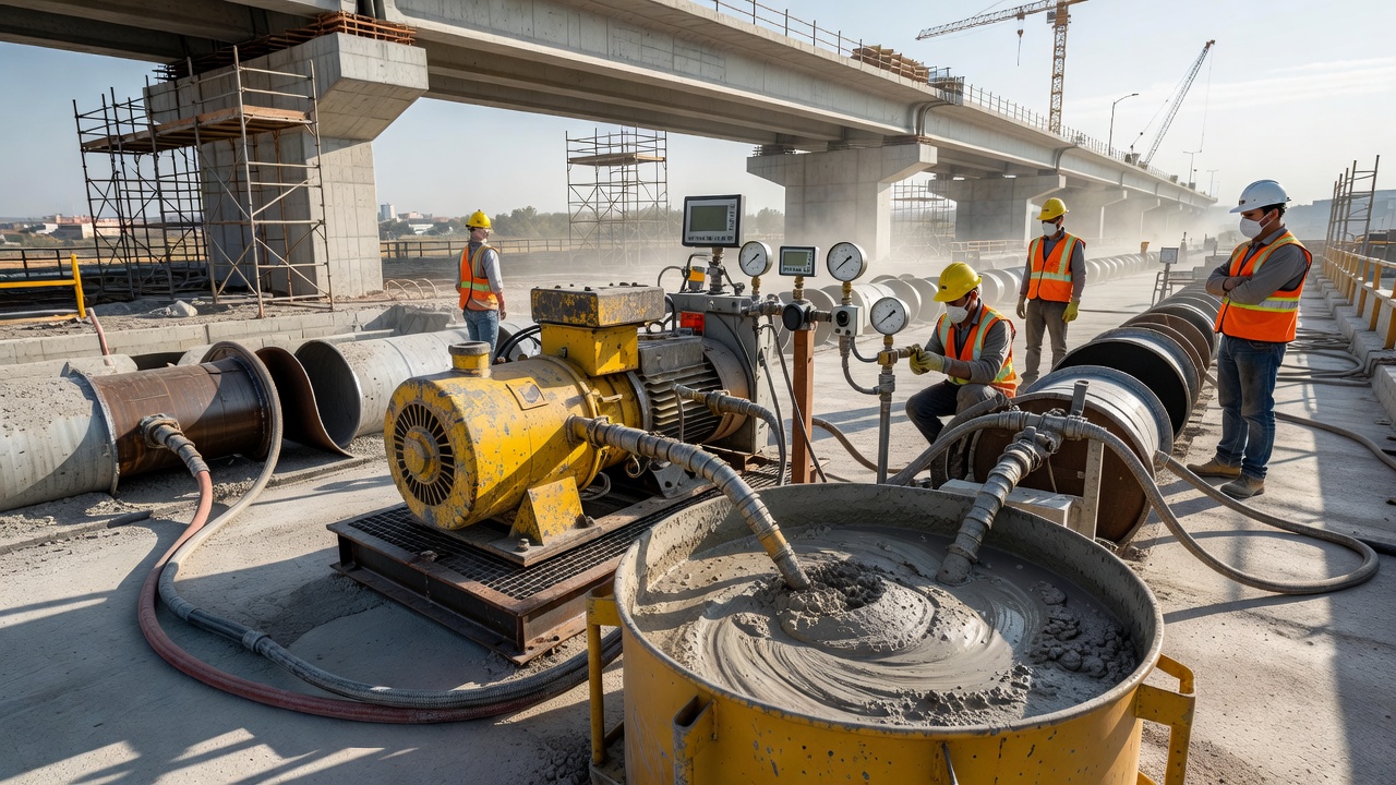
The pumping equipment used for pressure injection includes:
Piston pumps — Positive displacement pumps with a piston in a cylinder, providing high pressure (up to 5 MPa or 700 psi) but pulsating flow. Suitable for sanded grouts and thick grouts.
Progressive cavity pumps — A helical rotor turning inside a stator, providing continuous non-pulsating flow at moderate pressures (up to 1.5 MPa or 200 psi). Commonly used for post-tensioning tendon grouting.
Peristaltic (squeeze) pumps — A flexible tube compressed by rotating rollers, providing low pressure (up to 0.7 MPa or 100 psi). Suitable for small-volume injection and crack repair.
The injection pressure is a critical parameter that must be controlled within specified limits:
Application
Typical Injection Pressure
Maximum Pressure
Standard/Reference
Post-tensioning duct grouting
0.3–1.0 MPa (45–145 psi)
1.0 MPa at pump; 0.5 MPa at anchorage
FHWA-NHI-13-026
Crack injection (cementitious)
0.3–1.0 MPa (50–150 psi)
2.0 MPa (290 psi)
ACI 224.1R
Slab stabilization (undersealing)
0.14–0.35 MPa (20–50 psi)
0.5 MPa (70 psi)
FHWA HIF-20-058
Anchor grouting
0.5–2.0 MPa (70–290 psi)
3.5 MPa (500 psi)
—
Honeycomb repair
0.1–0.5 MPa (15–70 psi)
1.0 MPa (145 psi)
—
The injection procedure for pressure grouting follows a standardized sequence: surface preparation of the cavity opening, flushing with water, grout mixing in a high-shear colloidal mixer for 3 to 10 minutes, injection at the lowest point of the cavity progressing upward, a pressure hold of 30 seconds to 2 minutes, and port sealing.
The FHWA Post-Tensioning Tendon Installation and Grouting Manual specifies that during grout injection of tendon ducts, “the injection should start at the lowest grout inlet and proceed until grout of the same consistency emerges from the outlet” and that “the grout injection pressure should be limited to 1.0 MPa (145 psi) at the grout pump and 0.5 MPa (70 psi) at the tendon anchorage.”
Vacuum-Assisted Grouting
Vacuum-assisted grouting is a specialized placement method where a vacuum pump creates negative pressure at the outlet port before grout injection begins. The vacuum removes air from the cavity, creating a partial vacuum that draws the grout in and eliminates air pockets. This method achieves the highest level of fill completeness.
The vacuum grouting procedure involves sealing all grout inlet and outlet ports, applying vacuum (3 to 5 kPa absolute, approximately 95 to 97 percent vacuum) for 10 to 30 minutes, injecting grout at the inlet port while maintaining the vacuum, releasing vacuum after grout emerges at the outlet, and sealing all ports.
Vacuum grouting is specified for certain post-tensioning tendon grouting applications — particularly for tendons with complex profiles that include multiple high points (crests) where air would otherwise become trapped. The FHWA manual notes that “vacuum grouting is an effective method for grouting tendons that are not horizontal or have changes in profile that could trap air.”
Slab Stabilization and Undersealing by Grout Pour
Slab stabilization (also called undersealing, subsealing, or pavement grouting) is the injection of grout beneath concrete slabs to fill voids created by pumping, subgrade erosion, or consolidation. The purpose is to restore uniform support to the slab, reduce deflections under traffic loading, and extend the pavement service life. The FP2 (Foundation Performance Association) defines slab stabilization as “a nondestructive, void-filling, corrective process that restores slab support.”
The cementitious grout for slab stabilization is typically a sanded grout with sand-cement ratio of 2:1 to 3:1 by weight, water-cement ratio of 0.45 to 0.60, 28-day compressive strength of 7 to 20 MPa, maximum aggregate size of 3 to 6 mm, and slump of 200 to 250 mm.
The grout pour procedure for slab stabilization follows these steps:
Pavement analysis — FWD testing identifies areas with high slab corner deflections indicating void presence.
Hole drilling — 40 to 50 mm diameter holes are drilled through the slab at 1.0 to 1.5 m spacing, concentrated at slab corners and edges.
Grout mixing — The cementitious grout is mixed in a colloidal mixer to a uniform, flowable consistency.
Grout injection — Grout is pumped at 0.14 to 0.35 MPa (20 to 50 psi) with continuous monitoring of slab lift.
Hole plugging — After injection, holes are plugged with rapid-setting cementitious mortar.
Curing — The grout is allowed to cure for 24 to 72 hours before traffic is permitted.
Verification — Post-stabilization FWD testing confirms deflection reduction of at least 50 percent.
The estimated life extension from slab stabilization is 5 to 10 years. The procedure is most effective when performed before the onset of pavement damage (cracking, faulting) caused by loss of support.
Grouting of Honeycomb and Surface Voids
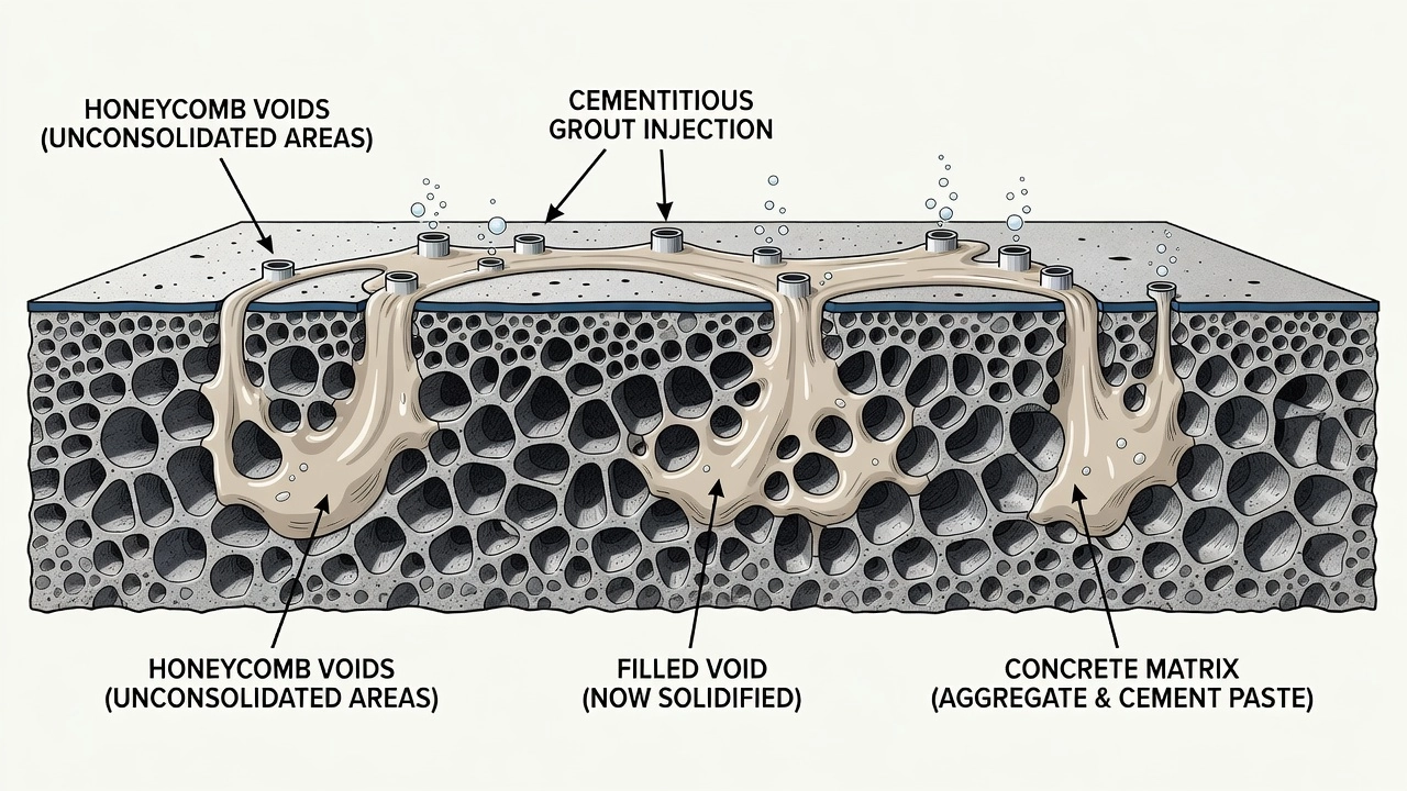
Honeycomb in concrete refers to areas where the coarse aggregate is visible on the surface with voids between aggregate particles, caused by inadequate consolidation (vibration) during concrete placement, congested reinforcement that impedes concrete flow, or a concrete mix with insufficient fines content.
The grout pour for honeycomb repair follows a systematic procedure: assessment of extent and depth, cavity preparation (removing loose material and cleaning), formwork placement for larger cavities, grout selection (sanded grout with sand-cement ratio of 1:1 to 2:1 for surface honeycomb, or coarser grout for deeper voids), grout placement by pouring or injection from the bottom up, and moist curing for 3 to 7 days.
The quality of the grout repair is assessed by visual inspection, sounding (tapping produces a solid sound), pull-off testing (ASTM C1583, minimum bond strength of 1.5 MPa for structural repairs), and core extraction to verify complete fill.
Grout Pour for Post-Tensioning Ducts
The grouting of post-tensioning tendon ducts is a specialized application with the most stringent requirements of any cementitious grouting operation. The grout serves two critical functions: corrosion protection of the prestressing steel and bonding between the tendon and the surrounding concrete. The FHWA Post-Tensioning Tendon Installation and Grouting Manual (FHWA-NHI-13-026) is the definitive reference.
Grout materials for post-tensioning ducts must meet specific performance requirements: 28-day compressive strength minimum 30 MPa, maximum water-cement ratio of 0.45, bleeding less than 2 percent after 3 hours, expansion of 0 to 10 percent in the plastic state, flow cone efflux time of 20 to 45 seconds, chloride ion content less than 0.1 percent by mass of cementitious materials, and sulfate content less than 4 percent.
The grout pour procedure for post-tensioning ducts includes pre-grouting inspection of the duct system, grout mixing in a high-shear colloidal mixer, on-site testing (flow cone every 5 batches, temperature every batch, bleeding test at start of production, compressive strength three cubes per day), grout injection at the lowest inlet port at 0.3 to 1.0 MPa, grout venting until same consistency grout emerges, and post-grouting sealing of all ports.
The FHWA Guidelines for Sampling, Assessing, and Restoring Defective Grout (FHWA-HRT-13-028) define physical deficiencies (PDs) of grout as “air voids, free water, and unhardened, segregated, or separated grout” and chemical deficiencies (CDs) as “chloride concentration in excess of what is specified.”
Inspection and Quality Assurance of Grout Pours
Inspection of a completed grout pour is essential to verify that the void has been completely filled and that the grout has achieved the required properties.
Inspection Method
Application
Standard
Detection Capability
Visual observation of grout return
Pressure grouting
—
Confirms grout emergence at outlet
Core sampling
All grout types
ASTM C42
Direct visual examination of fill and bond
Borescope inspection
Ducts, drilled holes
—
Visual inspection through small-diameter hole
Impact-echo testing
Ducts, slab-subgrade interface
ASTM C1383
Detects voids larger than 25 mm diameter
Ultrasonic pulse velocity
Ducts, tendon ducts
ASTM C597
Measures signal transit time; voids increase time
Ground penetrating radar
Slab-subgrade voids, ducts
—
Detects dielectric contrast at interfaces
Infrared thermography
Slab-subgrade voids
—
Detects thermal anomalies from voids
Grout volume accounting
All grout types
—
Compares injected volume to theoretical volume
Pull-off bond testing
Surface repairs
ASTM C1583
Measures tensile bond strength
Flow cone (fresh grout)
Quality control
ASTM C939
Verifies grout fluidity
Core sampling is the most definitive method for verifying grout fill completeness. A 50 to 100 mm diameter core is extracted through the grouted area, extending 25 to 50 mm into the surrounding concrete on both sides. The core is examined for grout continuity, bond interface condition, grout hardness and uniformity, and color consistency.
The acceptance criteria for grout fill completeness vary by application:
Tendon duct grouting — Maximum acceptability is a void larger than 10 mm in any dimension, or linear voids exceeding 100 mm in length. The FHWA guidelines state that the “target is zero voids” but recognize that small entrained air bubbles (less than 2 mm diameter) are unavoidable.
Crack injection — The repair should show complete fill of the crack cross-section, with no unfilled segments longer than 25 mm.
Slab stabilization — The void beneath the slab should be filled with grout to a minimum thickness of 3 mm over the entire area identified by FWD testing. Post-stabilization FWD deflection should be reduced by at least 50 percent.
Honeycomb repair — The cavity should be filled completely with no visible voids or surface depressions.
Grout Pour for Airport Concrete Pavements
Airport concrete pavements present unique requirements for cementitious grouting because of the combination of high wheel loads (aircraft weighing up to 600 metric tons for an A380), high tire pressures (up to 1.5 MPa), and the operational need for smooth, defect-free surfaces. The FAA Advisory Circular 150/5370-10H (Standard Specifications for Construction of Airports) and ICAO Aerodrome Design Manual (Doc 9157, Part 3) provide specifications for grouting in airport pavement applications.
Airport-specific grouting applications include:
Undersealing of rigid airport pavements — Filling voids beneath PCC slabs caused by pumping, subgrade erosion, or consolidation. The FAA requires grout for undersealing to have a 28-day compressive strength of at least 7 MPa and a maximum slump of 200 mm.
Dowel bar grouting — Grouting dowel bar slots in dowel bar retrofit (DBR) installations. The grout must achieve a minimum compressive strength of 28 MPa at 24 hours to minimize lane closure time, per FAA AC 150/5370-10H Item P-610.
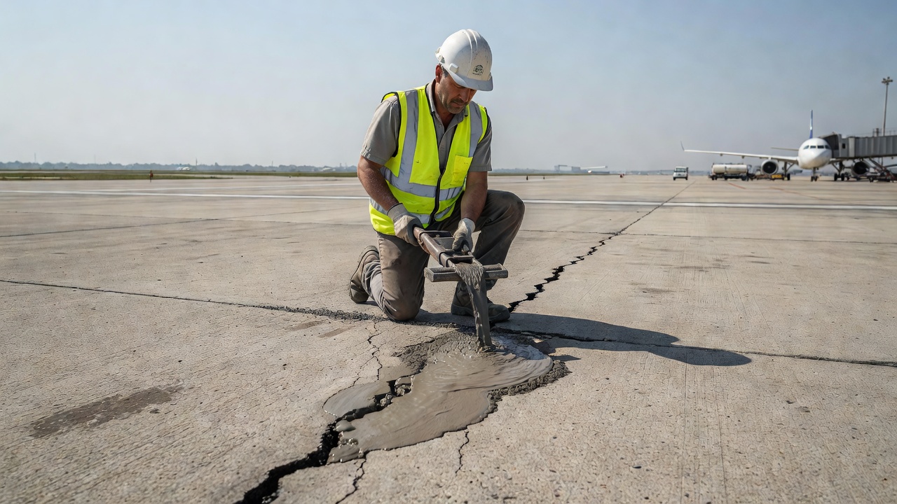
Crack repair — Injection of neat cement grout into non-structural cracks to seal against moisture infiltration.
Joint spall repair — Grouting of spalled areas at joints with a polymer-modified cementitious grout to restore joint integrity and prevent FOD.
Base course stabilization — Pressure grouting of cementitious grout into open-graded or poorly consolidated base layers to improve support.
The ICAO Airport Services Manual (Doc 9137, Part 2 — Pavement Surface Conditions) notes that pumping should be recorded during airport pavement condition surveys, and that slabs showing evidence of pumping should be investigated for subsurface voids. The recommended method for void detection in airport pavements is FWD testing, following FAA AC 150/5320-6G Appendix C.
Quality assurance for grout pours in airport pavements follows FAA requirements: grout materials must be certified, mixing must be documented, compressive strength tests must be performed at one set of three 50 mm cubes per day of grouting, post-grouting FWD testing must verify void filling effectiveness, and core samples must be extracted at a rate of one core per 100 m² of grouted area.
Summary of Grout Pour Specifications
Parameter
Neat Cement Grout
Sanded Cement Grout
Expanding Cement Grout
Composition
Cement + water
Cement + sand + water
Cement + sand + water + expanding agent
Water-cement ratio
0.35–0.50
0.45–0.55
0.40–0.50
Sand-cement ratio
—
0.5:1 to 3:1
1:1 to 2:1
28-day compressive strength
30–55 MPa
20–40 MPa
30–50 MPa
Expansion
None
None
0.5–4.0% (plastic state)
Bleeding (24 hr)
0.5–4.0%
0.5–2.0%
< 0.5%
Flow cone time (ASTM C939)
20–60 sec
30–60 sec
25–50 sec
Minimum crack filling width
0.5–1.0 mm
3.0–5.0 mm
0.5–2.0 mm
Maximum pour thickness (single lift)
25–50 mm
50–150 mm
50–200 mm
Typical applications
Crack injection, duct grouting, anchorage
Slabjacking, honeycomb repair, baseplate grouting
Tendon duct grouting, anchor grouting
The selection of the appropriate grout type and placement method for a grout pour depends on the void geometry, accessibility, performance requirements, and cost. Neat cement grout offers the highest fluidity and penetration capability but the highest shrinkage and bleeding risk. Sanded grout offers better dimensional stability and lower cost but cannot penetrate narrow openings. Expanding grout combines the advantages of both with the added benefit of shrinkage compensation, but at higher material cost and with more demanding quality control requirements.
Proper execution of a grout pour — including surface preparation, mixing, placement, curing, and inspection — is as important to the success of the repair as the material selection. The FHWA, FAA, ACI, and ASTM standards provide comprehensive guidance for each of these elements, and compliance with the applicable standards is essential for achieving a durable, effective grout repair.
Frequently Asked Questions
Neat cement grout consists of only portland cement and water, with a water-cement ratio typically ranging from 0.35 to 0.50. It achieves high compressive strengths of 30 to 50 MPa at 28 days and can penetrate very narrow openings as small as 0.5 mm, making it suitable for crack injection (non-structural), tendon duct grouting, and anchoring applications. Sanded cement grout incorporates fine aggregate (sand) passing a No. 16 sieve (1.18 mm) at a sand-to-cement ratio of 0.5:1 to 3:1 by weight. The sand reduces shrinkage, improves dimensional stability, and provides better strength in thicker sections. Sanded grout is used for filling larger voids exceeding 10 mm width, honeycomb repair, under-slab grouting (slabjacking), and grouting around anchors or dowels. The addition of sand increases the yield (volume per unit weight of cement) and reduces the heat of hydration. However, sanded grout cannot penetrate cracks narrower than about 3 mm because the sand particles bridge the opening.
Inspection of grout pour completeness employs both direct and indirect methods. Direct methods include: (1) visual inspection of grout return at outlet ports during pressure grouting — when grout of the same consistency emerges, the void is considered filled; (2) core sampling — extracting 50 to 100 mm diameter cores through the grouted area allows direct examination of grout continuity, bond, and the absence of voids; (3) borescope inspection — inserting a rigid or flexible borescope into small-diameter observation holes or core holes to visually inspect the grout condition. Indirect (non-destructive) methods include: (4) impact-echo testing — sending a mechanical pulse through the concrete and analyzing the reflected signal; voids create a distinct low-frequency resonance; (5) ultrasonic pulse velocity (UPV) — measuring the transit time of ultrasonic waves through grouted versus ungrouted areas; voids increase transit time; (6) ground penetrating radar (GPR) — detecting dielectric contrast between grout, air voids, and concrete; (7) infrared thermography — detecting temperature differences caused by differential thermal conductivity between solid grout and voids. For post-tensioning duct grouting, the FHWA requires that grout outlets be monitored until grout of the same consistency emerges (indicating complete fill), and that an inspection port be provided at each anchorage for visual confirmation.
Expanding cementitious grout contains admixtures that generate a controlled expansion during the plastic state, typically 0.5 to 4.0 percent linear expansion. The most common expanding agent is aluminum powder (approximately 0.005 to 0.05 percent by weight of cement), which reacts with the alkaline hydroxide ions in cement pore water to produce microscopic hydrogen gas bubbles. The gas formation creates a slight expansion that compensates for the settlement and drying shrinkage that would otherwise leave voids at the interface between the grout and the surrounding surfaces. Other expanding agents include gas-forming chemicals (calcium nitrite with aluminum, or organic gas-forming compounds) and pre-hydrated expansive cements (Type K, Type M, or Type S cements as defined in ASTM C845). Expanding grout is essential for applications where bond to the existing concrete or substrate is critical, such as tendon duct grouting (where any void exposes the prestressing steel to corrosion), anchor bolt grouting, baseplate grouting under machinery, and under-slab void filling. The FHWA Post-Tensioning Tendon Installation and Grouting Manual (FHWA-NHI-13-026) specifies that grout for post-tensioning tendons must have an expansion of 0 to 10 percent while in the plastic state to compensate for bleed water settlement and plastic shrinkage. The expansion must occur before the grout sets (typically within 30 to 60 minutes of mixing) and must not continue after setting, as post-set expansion can damage the surrounding concrete or duct.
Gravity pour is the simplest placement method, relying on the hydrostatic head of the grout column to fill the cavity. The grout is poured from above through a funnel, tremie tube, or funnel-shaped port at the highest point of the cavity. Gravity pouring is suitable only for vertical or steeply inclined cavities with a minimum opening width of approximately 10 mm, where the grout can flow downward under its own weight without trapping air pockets. The maximum vertical height for gravity pouring without a tremie is about 1 to 1.5 meters. Gravity pouring has no mechanism for forcing grout into narrow crevices or for displacing standing water from the void. Pressure injection uses a pump (piston-type, peristaltic, or progressive cavity pump) to force grout into the cavity at controlled pressures. For crack injection, pressures range from 0.3 to 1.0 MPa (50 to 150 psi) for low-pressure systems up to 2.0 to 5.0 MPa (300 to 700 psi) for high-pressure systems. For tendon duct grouting, the FHWA specifies a maximum injection pressure of 1.0 MPa (145 psi) at the grout pump and 0.5 MPa (70 psi) at the tendon anchorage. For slab stabilization (undersealing), injection pressures are typically 0.14 to 0.35 MPa (20 to 50 psi), carefully controlled to avoid lifting the slab. Pressure injection forces grout into every crevice, displaces air and water ahead of the grout front, and can fill voids as narrow as 0.5 mm. Vacuum-assisted grouting is a specialized variant where a vacuum pump creates negative pressure (typically 3 to 5 kPa absolute, or about 95 percent vacuum) at the outlet port before grout injection begins. The vacuum removes air from the cavity, allowing the grout to flow in under reduced resistance and achieving virtually void-free filling. Vacuum grouting is specified for certain post-tensioning tendon grouting applications to eliminate air pockets at the tendon crests.
Slabjacking, also called mudjacking or pressure grouting, is a method for levelling settled concrete slabs by injecting grout beneath them under controlled pressure. The process involves: (1) drilling 40 to 50 mm diameter holes through the slab at predetermined locations (typically 1.0 to 1.5 m spacing in a grid pattern covering the settled area); (2) inserting a grout injection nozzle into each hole and sealing the annulus; (3) pumping a cementitious grout (typically a sanded grout with a sand-cement ratio of 2:1 to 3:1 by weight and a water-cement ratio of 0.45 to 0.60) under pressure into the void between the slab and the underlying subgrade; (4) continuing injection until the slab begins to lift, grout returns through adjacent holes, or the maximum specified pressure is reached; (5) plugging the injection holes with a rapid-setting cementitious mortar; (6) monitoring slab elevation during injection with laser levels or stringlines to achieve the target grade. The slab is typically lifted no more than 6 mm per pass and multiple passes over several days may be required for slabs that have settled more than 25 to 50 mm. Cementitious grout is preferred for slabjacking because it provides high compressive strength (typically 7 to 20 MPa at 28 days), uses locally available materials, and costs less than polyurethane alternatives. The FAA and FHWA slab stabilization guidelines specify that the grout should have sufficient fluidity to penetrate voids as thin as 3 mm, a setting time of 2 to 4 hours, and a 28-day compressive strength of at least 7 MPa. The grout should not contain particles larger than 6 mm to avoid bridging in the injection system.
Upgrade your concrete repair inspection
TarmacView provides AI-powered pavement inspection solutions that help identify areas requiring grout repair and verify the quality of completed grouting work. Schedule a demonstration to see how our technology enhances quality assurance for cementitious grouting operations.
Grouting is the injection of cementitious grout into post-tensioning tendon ducts after stressing, providing bond between tendon and concrete, and protecting th...
Dry pack mortar is a very stiff, low-water-content cement mortar rammed into confined repair areas (spall pockets, cone bolt holes, narrow slots), achieving hig...
Pervious concrete (also called permeable or porous concrete) is a concrete with high interconnected void content (15-35%) allowing water to pass through, reduci...
31 min read
Concrete Materials
Drainage
+2
Cookie Consent We use cookies to enhance your browsing experience and analyze our traffic. See our privacy policy.