Post-Tensioning Duct (PT Duct)
A PT duct is a sheath or conduit encasing post-tensioning tendons in concrete, creating a void for tendon movement during stressing and providing a path for pro...
28 min read
Reinforcement
Concrete
+3
Grouting is the injection of cementitious grout into post-tensioning tendon ducts after stressing, providing bond between tendon and concrete, and protecting the steel from corrosion by creating an alkaline environment and physical barrier. Incomplete grouting is the leading cause of tendon corrosion. Covers grout materials, injection procedures, quality control, and inspection for grout voids.
Grouting of post-tensioning ducts is the process of injecting cementitious grout into the ducts, sheaths, or conduits that contain post-tensioning (PT) tendons after the stressing operation has been completed. In bonded post-tensioning systems, this operation transforms the unbonded tendon assembly — where the strand is free to move within the duct — into a bonded system where the tendon is mechanically and chemically locked to the surrounding concrete. The grouting process is the final and arguably most quality-critical step in post-tensioned concrete construction.
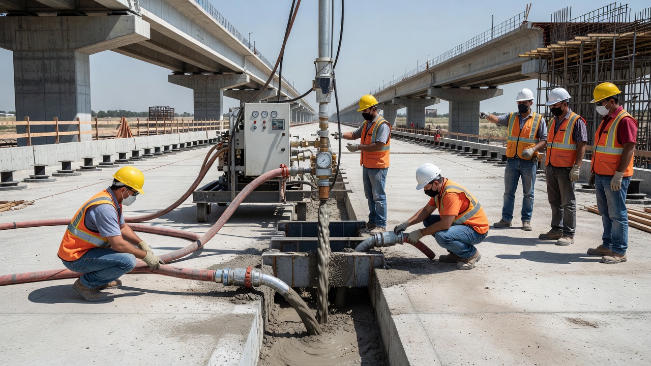
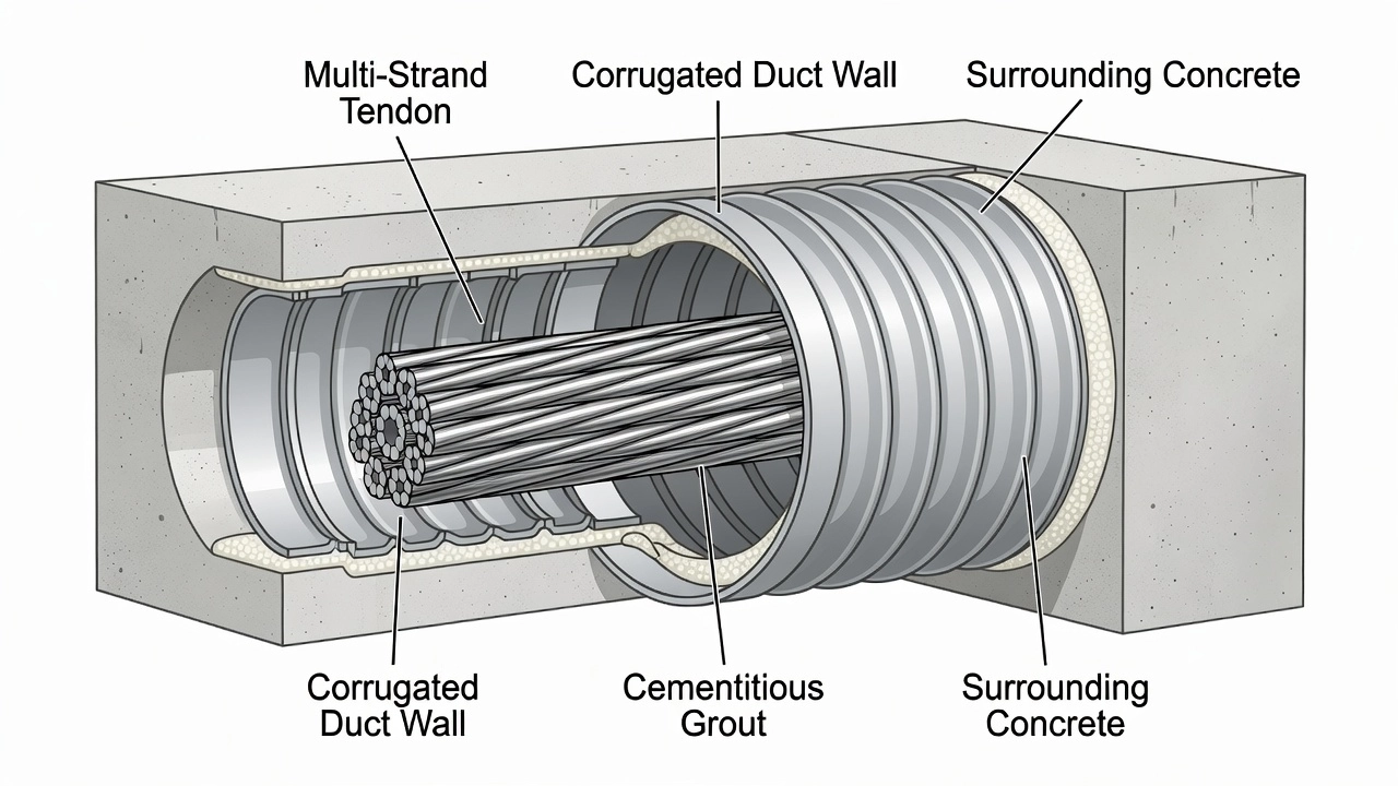
The grout is a carefully proportioned mixture of portland cement, water, and — in modern practice — chemical and mineral admixtures that produce a fluid, workable, stable suspension at low water-cement ratio. It is pumped into the duct through a grout inlet at the lowest point of the tendon profile, displacing air and any accumulated water upward toward vents at high points and anchorages. Upon hardening, the grout fills all void spaces within the duct, including the intricate interstitial spaces between the individual wires or strands of the multi-strand tendon assembly.
The term is defined across multiple international standards. PTI M55.1-12 (Specification for Grouting of Post-Tensioned Structures) states: “Grout shall be a mixture of cementitious materials, mineral supplements, chemical admixtures, and water proportioned to produce a flowable, stable, non-bleed, and non-segregating suspension that will harden to provide corrosion protection to the prestressing steel and bond the steel to the structure.” EN 447:2007 defines grout as “a cement-based mixture designed to fill ducts in post-tensioned concrete, to protect the reinforcement against corrosion and, where required, to provide bond between the prestressing steel and the surrounding concrete.”
Cementitious grouts have been used for over 50 years for tendon protection. Prior to 2001, most PT grouts were simple field mixtures of portland cement and water, with water-cement ratios (w/c) typically specified between 0.47 and 0.53, and sometimes containing expansive admixtures. These simple mixtures performed adequately under many conditions. However, a series of high-profile tendon failures in the late 1990s and early 2000s — including the Niles Channel Bridge, Florida Keys (1999, failure after 16 years), Sunshine Skyway Bridge, Tampa (2000, failure after 13 years), and Mid Bay Bridge, Destin, Florida (2000, failure after only 6 years) — revealed that these simple grouts were prone to bleeding, segregation, and void formation when used in the demanding conditions of bridge construction. These failures triggered a fundamental shift in the industry, led by research from the Virginia Department of Transportation (VDOT) and the Federal Highway Administration (FHWA), culminating in the widespread adoption of prepackaged, high-performance, bleed-resistant thixotropic grouts and more rigorous quality control procedures.
Grouting fulfills three primary and interrelated functions in bonded post-tensioned concrete structures.
Corrosion Protection is the most critical function. Prestressing steel — typically seven-wire strand conforming to ASTM A416 — is manufactured from high-carbon steel with a tensile strength of 1,860 MPa (270 ksi). This steel is inherently susceptible to corrosion, and because it operates at 70–80% of its ultimate tensile strength, even minor cross-section loss from pitting can cause catastrophic brittle fracture. The grout protects the steel through two complementary mechanisms: chemical passivation and physical barrier formation. The cementitious grout provides a highly alkaline environment with a pH of 12.5 to 13.5. At this pH, a tightly adhering passive iron oxide layer — the passivation film — forms spontaneously on the steel surface, rendering it immune to general corrosion. This passivation layer is thermodynamically stable as long as the high pH is maintained and chlorides do not reach the steel surface in sufficient concentration. Simultaneously, the hardened grout forms a dense, low-permeability physical barrier that prevents moisture, oxygen, dissolved chlorides, and other aggressive agents from reaching the steel surface. The grout fills not only the gross duct cross-section but also the capillary spaces between individual wires of the strand.
Bond and Force Transfer ensures the composite action essential to prestressed concrete behavior. In bonded post-tensioning, the prestressing force is transferred from the tendon to the concrete not solely through the anchorage devices at the ends, but also progressively along the entire tendon length through the bond between the strand, the grout, and the duct wall — and hence to the surrounding concrete. This bond comprises three components: adhesion between grout and steel, mechanical interlock from the twisted strand geometry bearing against the hardened grout, and the Hoyer effect (the wedging action of the strand due to Poisson’s ratio effects when tension is released). The bond enables the tendon and concrete to act as a unified structural element. In the event of a strand break in a fully grouted system, the bond allows re-anchoring of the broken strand within the grout — the broken end can re-establish force transfer on either side of the fracture, providing important structural redundancy. In ungrouted regions, this re-anchoring cannot occur, and a single strand break can lead to progressive failure of the entire tendon.
Physical Barrier and Structural Stiffening completes the grout’s function. The hardened grout mechanically restrains the strands, preventing relative movement and fretting between adjacent wires within the strand bundle. It also contributes to the overall stiffness of the finished tendon assembly. The grout seals the duct against the ingress of aggressive agents and provides a uniform, continuous load path. Without grout, the tendon remains a collection of individual wires within a voided duct, vulnerable to moisture accumulation, strand vibration, and fretting fatigue.
Modern PT grouts are sophisticated, engineered materials designed to meet demanding performance requirements. The selection of grout type depends on the exposure environment, tendon geometry, construction constraints, and applicable standards.
Neat Cement Grout is the simplest formulation — a mixture of portland cement and water, typically at w/c ratios of 0.47–0.53. It was the predominant grout used worldwide prior to 2001. While economical and easy to produce, neat cement grout is prone to several fundamental deficiencies. At the high w/c ratios needed for pumpability, bleed water separation is inevitable — pre-2001 grouts exhibited approximately 4% bleeding in wick-induced bleed testing. The grout also tends to segregate, with heavier cement particles settling and lighter fractions rising. The segregation produces gradients in strength, permeability, and chemical composition across the tendon cross-section. Neat cement grouts continue to be permitted only for non-corrosive, dry environments under Class A of the PTI classification system, and are rarely specified for critical structures such as bridges, parking garages, or marine structures.
Prepackaged (Pre-bagged) Grouts are factory-produced blends of portland cement, mineral admixtures, and chemical admixtures in proprietary formulations. The dry ingredients are precisely proportioned, quality-controlled, and packaged in sealed bags. Only a specified volume of potable water is added on site, followed by high-shear mechanical mixing. Prepackaged grouts provide consistent quality, eliminate field batching errors, and incorporate advanced admixture systems that achieve near-zero bleed, controlled expansion, and stable rheology at low w/c ratios. PTI M55.1-12 requires that prepackaged grouts be used within six months of the date of manufacture, with on-site storage limited to a maximum of one month under controlled temperature conditions. Class D is the PTI designation for prepackaged grouts meeting all performance requirements through proprietary formulations.
Thixotropic Grouts represent the state of the art in PT grouting technology. These grouts exhibit a rheological property called thixotropy: they are fluid and pumpable when subjected to shear during mixing and injection, but revert to a gel-like consistency when at rest. This property is critical for grouting performance because the gel-like consistency at rest prevents sedimentation of cement particles — the root cause of bleed water formation. Thixotropic grouts achieve essentially zero bleed under standard testing conditions. They also exhibit superior resistance to segregation, maintain stable rheology over the required working time, and provide uniform properties throughout the tendon length. Since 2001, thixotropic, bleed-resistant prepackaged grouts have been the standard for bonded PT construction in the United States for all but the least corrosive environments.
PTI Grout Classifications (M55.1-12) define four progressive performance levels:
| Class | Composition | Application |
|---|---|---|
| Class A | Cement + water | Non-corrosive environments only |
| Class B | Cement + water + chemical admixtures (plasticizers, anti-bleed agents) | Moderate exposure |
| Class C | Cement + water + mineral supplements (fly ash, slag Grade 120, undensified silica fume) + chemical admixtures | Aggressive environments |
| Class D | Prepackaged, factory-blended proprietary formulations meeting ALL performance requirements | Critical structures, all environments |
Water-Cement Ratio Requirements are among the most rigorously controlled parameters in PT grouting because of their dominant influence on grout properties. Modern specifications strictly limit the w/c ratio:
| Standard | Maximum w/c ratio |
|---|---|
| PTI M55.1-12 | 0.45 (by weight) |
| EN 447:2007 | 0.44 (plain cement grout); 0.42 with high-alkali mineral additions |
| FAA/VDOT specifications | 0.45 maximum |
| Typical prepackaged grouts | 0.28–0.38 |
The relationship between w/c ratio and grout quality is non-linear and critical. VDOT testing demonstrated that at w/c = 0.55, a prepackaged grout that performed perfectly at 0.38 began to bleed and segregate, producing soft, low-quality grout. At w/c = 0.65, the same grout produced a lower-strength foamy mass. Cube compressive strength drops sharply with increasing w/c ratio: a grout achieving 8,000 psi at w/c = 0.33 may drop below the 5,000 psi minimum at w/c = 0.50.
Admixtures are essential components of modern PT grouts. Plasticizers (high-range water reducers or superplasticizers) are used to achieve adequate fluidity and pumpability at low w/c ratios. Typical dosage: 1.0–1.6% by weight of cement. Anti-bleed agents (also called viscosity-modifying admixtures) reduce or eliminate water separation. These are critical for modern high-performance grouts and are used in conjunction with thixotropic properties. Expansive agents compensate for chemical and autogenous shrinkage during early hydration. PTI M55.1-12 requires volume change of 0.0% to +0.2% at 28 days per ASTM C1090. Set control admixtures (accelerators or retarders) manage working time based on ambient temperature conditions. Corrosion inhibitors provide additional chemical protection and are sometimes specified for marine or de-icing salt environments.
Fresh and Hardened Grout Properties are specified in detail by PTI M55.1-12 and EN 447:
| Property | PTI M55.1-12 | EN 447:2007 |
|---|---|---|
| Initial efflux time (flow cone) | 11–30 sec (ASTM C939); 6–20 sec (modified cone) | 12–25 sec |
| Efflux at 30 minutes | Max 30 seconds | Max 25 seconds |
| Bleeding (standard) | 0% at 3 hours (ASTM C940) | ≤0.3% (inclined tube, EN 445) |
| Wick-induced bleed | 0% | — |
| Volume change at 28 days | 0.0% to +0.2% | 0–3% after 24 hours (prism method) |
| 28-day compressive strength | Min 34.5 MPa (5,000 psi) | Min 30 MPa (4,350 psi) |
| Chloride content | Max 0.08% by weight of cementitious | Max 0.1% by weight of cement |
| Rapid chloride permeability | Max 2,500 coulombs (AASHTO T 277) | — |
Grouting procedures are governed by strict protocols to ensure complete filling, proper consolidation, and long-term performance. The operation is performed after stressing is complete and all anchorages are sealed, typically within 7–14 days of stressing.
General Principles require that grout inlets be located at or near the lowest point of the tendon profile. Outlets must be provided at all anchorages, at high points where the vertical rise exceeds 500 mm (20 inches), and at major cross-section changes. All inlets and outlets must be fitted with positive shut-off valves capable of withstanding the grout injection pressure. Grouting is a continuous, uninterrupted operation: once started, grout must be pumped continuously until grout of consistent quality emerges from all outlets, with no stoppages longer than the grout’s working time.
Pre-grouting Checks are mandatory before any grout is mixed. The duct system must be verified clean, unobstructed, and watertight through an air pressure test. The FHWA-NHI-13-026 manual requires that the duct be pressurized to approximately 0.1 MPa (15 psi) for five minutes, with pressure drop not exceeding 10%. For external tendons, the duct is visually inspected along its entire length to verify that all connections, transitions, and anchorage seals are intact. All vents, outlet tubes, and grout caps must be sealed and fitted with valves. The grout plant — typically a high-speed colloidal mixer with a holding tank and positive-displacement pump — must be tested and calibrated.
Pressure Grouting is the conventional method. Grout is pumped at controlled pressure from the lowest injection point. PTI M55.1-12 limits maximum injection pressure to 1.0 MPa (145 psi) at the inlet. The grout rises in the duct, displacing air and any accumulated water ahead of it toward high-point vents and anchorages. As grout of consistent quality emerges from each vent, the vent is sequentially closed. Holding pressure of approximately 0.5 MPa (72 psi) is maintained after all outlets have discharged consistent grout, typically for two to five minutes, before the inlet is sealed. The pressure hold ensures that any remaining small cavities or bleed channels are filled and that the grout is consolidated under pressure.
Vacuum-Assisted Grouting is an enhanced procedure developed specifically to address the problem of trapped air, particularly in long, complex, or multi-peak tendon profiles. Before any grout is mixed, the tendon duct is subjected to a vacuum of 85–90% — corresponding to an absolute pressure of approximately 0.01–0.02 MPa (1.5–3 psi). PTI M55.1-12 requires a minimum vacuum of −0.07 MPa (525 mmHg) before grout injection. With the vacuum established, grout is drawn into the duct by the pressure differential between atmospheric pressure at the grout inlet and the near-vacuum within the duct. Positive pressure pumping assistance is typically used in combination with vacuum. The advantages of vacuum grouting are significant: it virtually eliminates air pockets and trapped air voids, provides superior filling of the intricate interstitial spaces between individual strands, and is particularly effective for tendons with multiple high points, long horizontal runs, or complex geometry. Since 2001, vacuum grouting has been extensively used in US segmental bridge construction, particularly by VDOT and the Florida Department of Transportation (FDOT). The Varina Enon Bridge tendon repair program (2003–2004) used vacuum grouting to fill known voids.
Venting Protocol requires that all vents be opened sequentially from the injection point outward. Each vent is closed only when grout of consistent quality — matching the injected grout in color, consistency, and efflux time — emerges continuously. Grout of watery consistency, discolored grout, or grout containing air bubbles indicates that venting should continue. The final discharge is typically from the most distant anchorage vent, where holding pressure is applied and maintained.
Grout bleed is the single most consequential physical phenomenon affecting PT grouting quality and durability. Bleed is the separation of water from the solid cementitious constituents of fresh grout due to gravity-driven sedimentation of heavier particles.
Mechanism of Bleed begins as soon as the grout is placed in the duct. Cement particles, being denser than water, begin to settle. As the particles consolidate, excess water is displaced upward. In a standard vertical cylinder test (ASTM C940), this water collects on the surface as a distinct clear layer. In a PT duct, which is a closed system, bleed water cannot escape. It migrates upward along the tendon profile, accumulating at the highest geometric points — typically the anchored ends of draped tendons, at deviators in external tendons, and along the top of horizontal or gently sloped sections. The accumulated water forms lenses or pockets at these high points.
The Wick Effect is a critical phenomenon that amplifies the damage from even small amounts of bleed water. The interstitial spaces between individual wires in a seven-wire strand, and between adjacent strands in a multi-strand bundle, act as capillary wicks. These wicks channel bleed water along the length of the tendon, often over significant distances, toward low-restraint paths and collection points. The wick effect means that even grouts with modest bleed — which in a standard vertical cylinder might show minimal water separation — can produce substantial voids in actual tendon conditions because the wicks efficiently transport bleed water to high points from along the entire tendon length.
Bleed Tests per Standards have evolved to better represent real tendon conditions:
| Test Method | Standard | Acceptance Criteria |
|---|---|---|
| Standard bleeding test | ASTM C940 | 0% bleeding at 3 hours (modern spec) |
| Wick-induced bleed test | Modified ASTM C940 | 0% bleeding (strand wicks included) |
| Inclined tube test | EN 445 | ≤0.3% bleed |
| Pressure bleed test | ASTM C1741 / Schupack | 0–4% bleed under 0.5 MPa |
The wick-induced bleed test was developed specifically because standard ASTM C940 testing did not capture the wick effect. In this test, strands are placed in the graduated cylinder alongside the grout, providing a wick path that simulates the capillary action of actual tendons. This test reveals bleed behavior far more representative of field conditions. PTI M55.1-12 requires the wick-induced bleed test for all grout prequalification.
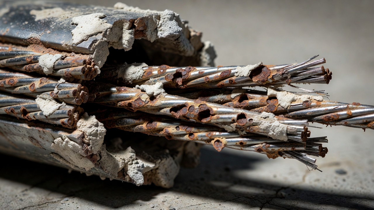
Consequences of Bleed extend beyond the formation of air-filled voids. As bleed water rises, it carries fine cement particles, sulfate ions, potassium, and sodium compounds to the surface. When this water evaporates or is absorbed during curing, it leaves behind a white, chalky residue — a segregated grout layer with elevated sulfate content and extreme alkalinity (pH 13–14). This soft grout or exudate is a fundamentally corrosive material that never gains proper strength and actively attacks the prestressing steel. The Varina Enon Bridge investigation (2002–2007) established that bleed voids of approximately 4% of tendon length were present at anchorages. Critically, the investigation found that strands inside the air-filled voids were not necessarily corroding — some remained passivated even after 11 years — but strands in the segregated, sulfate-enriched soft grout immediately below the voids were corroding aggressively. This finding revolutionized the understanding of grout defect mechanisms: the void itself is not the immediate corrosion threat; rather, the segregated product that formed as a result of the bleed is the corrosive agent.
Grouting defects fall into several distinct categories, each with specific mechanisms, risks, and detection signatures.
Voids are the most common grouting defect. A void is an open space within the duct where grout should be present. Voids form through four primary mechanisms: bleed water accumulation at high points with subsequent evaporation or absorption (the most common cause in draped tendons); trapped air due to inadequate venting (particularly at complex profile transitions); grout leakage through unsealed ducts, connections, or damaged sheathing before the grout has hardened; and incomplete filling due to insufficient grout volume, premature termination of pumping, or blocked ducts. Voids are classified by location: anchor head voids at the anchorage — the highest point in draped tendons; top-of-duct voids along the upper surface of horizontal or gently sloped sections; interstitial voids between individual strands within the bundle; and full-section voids where the entire duct cross-section is unfilled for a length.
Bleed Water Lenses are thin layers of water trapped between the grout and the upper duct wall. These are transient features that later leave thin, planar voids. In vertical or steeply inclined tendons, intermittent water pockets can form where rising water is trapped by strand congestion at deviators.
Soft Grout / Segregated Exudate is characterized by a white, soft, unhardened paste that is the exudation product of grout segregation. This material has been described in FDOT investigation reports as “a segregated material with high moisture content and enhanced sulfate content.” Soft grout was directly implicated in the Ringling Causeway Bridge failure (2011), where it surrounded corroded strands that failed catastrophically after only eight years of service. The material typically exhibits pH of 13–14, elevated sulfate and potassium concentrations, and never gains structural strength. Soft grout can remain in a non-hardened state indefinitely, creating localized corrosion cells. In one documented European case (Carsana & Bertolini, 2015), a tendon failed in under two years due to soft grout conditions.
Segregation broader than soft grout involves the separation and stratification of all grout constituents. Heavier cement particles settle to the bottom of the duct, while lighter components — water, soluble sulfates, fine particles — migrate upward. This creates systematic gradients in strength, permeability, and chemical composition across the duct cross-section. The lower portion may be dense and strong while the upper portion is weak, porous, and chemically aggressive.
Incomplete Filling describes conditions where the duct is only partially filled. This may result from insufficient grout volume, undetected leakage, blocked ducts, or premature termination of the grouting operation. Incomplete filling is detectable through volume tracking during injection — the ratio of actual volume pumped to theoretical duct volume should be 1.05–1.15. A ratio below 1.05 strongly suggests incomplete filling.
Quality control during grouting is a comprehensive process involving continuous monitoring of multiple parameters to verify that the grout meets specification requirements and that the duct is completely filled.
Injection Pressure Monitoring is performed continuously during pumping. Maximum pressure at the inlet is limited to 1.0 MPa (145 psi) per PTI M55.1-12, with an absolute upper limit of 1.5 MPa (218 psi) under no circumstances. The minimum pressure must be sufficient to overcome the gravity head from the injection point to the highest vent plus friction losses — typically 0.3–0.7 MPa depending on tendon length and profile. Pressure gauges must have accuracy of ±2%. Modern commercial grouting systems use electronic pressure transducers with continuous digital recording at time-stamped intervals, providing a permanent record of the pressure history for each tendon.
Volume Tracking compares the theoretical grout volume — calculated from the internal duct cross-sectional area minus the cross-sectional area of the strands, multiplied by the tendon length — with the actual volume pumped as measured by the grout pump’s displacement counter or a flowmeter. The expected ratio of actual-to-theoretical volume is 1.05–1.15, accounting for interstitial strand spaces (the actual void volume in an ungrouted duct is significantly less than the gross duct cross-section because the strands occupy substantial volume), surface irregularities in the duct wall, and minor leakage. An excessively high ratio indicates uncontrolled leakage requiring immediate investigation. An excessively low ratio indicates incomplete filling or blockage.
Temperature Monitoring is critical because grout hydration is temperature-dependent. The acceptable grout temperature at the time of injection is 10–32°C (50–90°F). The preferred temperature range at mixing is 15–30°C (60–85°F). Above 32°C (90°F), accelerated hydration reduces working time and risks flash setting, blockage, and incomplete filling. Below 10°C (50°F), hydration slows to the point where prolonged bleeding can occur before the grout gains sufficient structure to resist sedimentation. Cold-weather precautions include heating of mixing water (not to exceed 65°C / 150°F) and pre-heating of dry materials. Hot-weather precautions include using chilled mixing water, shading materials and equipment, and performing grouting during cooler periods of the day.
Flow Cone Testing (ASTM C939) is the primary field control test for grout fluidity. A conical funnel with a 12.7 mm (0.5 inch) orifice is filled with 1,725 mL of grout. The time for the grout to flow through the orifice — the efflux time — is measured. Per PTI M55.1-12, the initial efflux time must be 11–30 seconds, and the efflux time after 30 minutes of agitation in the holding tank must not exceed 30 seconds. The test is performed at least once per tendon and whenever the grout consistency appears to change. During continuous grouting operations, testing is required at commencement and every 30 minutes. PTI also specifies a modified flow cone with a different fill procedure, giving an acceptance range of 6–20 seconds initial efflux.
Cube Strength Testing is performed on 50 mm (2-inch) grout cubes per ASTM C109. The minimum 28-day compressive strength is 34.5 MPa (5,000 psi) per PTI M55.1-12. Typical high-performance grouts achieve 48–62 MPa (7,000–9,000 psi). Cubes are prepared at the same frequency as flow cone tests — at least one set of three cubes per tendon. On the VDOT US-460 project, three samples taken from the outlet end of tendons showed 14-day strengths of 4,665–6,135 psi and 28-day strengths of 7,885–8,705 psi, confirming uniform, properly mixed grout throughout the tendon length.
Grout Certificates and Documentation are required by PTI M55.1-12. The contractor must provide material certificates from the manufacturer for each grout batch, mix design certification, preconstruction test verification of all performance requirements, daily grouting reports for each tendon (including tendon identification, injected volume, pressure vs. time data, temperature, flow cone times, and cube strengths), and proof of personnel certification — all grouting operators and inspectors must hold current PTI Bonded PT Installer certification or ASBI grouting technician certification.
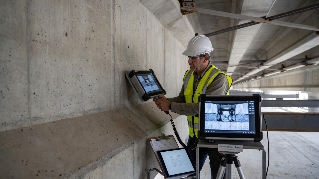
Non-destructive testing for grout void detection has become a standard practice for condition assessment of existing post-tensioned structures, particularly where grouting quality is suspect or where tendon failures have occurred. Multiple complementary methods are available, each with specific capabilities and limitations.
Impact-Echo (IE) uses a mechanical impact — typically a steel sphere propelled by a spring-loaded solenoid — to generate stress waves that propagate through the concrete and reflect from internal interfaces such as ducts, voids, and the far surface. A contact transducer detects the reflected waves, and the frequency content of the signal reveals the depth and nature of reflecting interfaces. A solidly grouted duct produces a reflection signature similar to solid concrete. A void-containing duct produces a distinct low-frequency signal indicating a high-amplitude reflection at the void boundary. Impact-echo is effective at detecting voids within 150–600 mm (6–24 inches) of the surface, can differentiate between solid grout and void, and detects voids as small as 10% of duct cross-section. Scanning speed is 10–20 ft² per hour per channel. The method was successfully used on the Varina Enon Bridge to identify void locations, which were subsequently verified through borescope openings. Limitations include difficulty with closely spaced ducts (signal interference), metallic ducts masking internal conditions, and limited precision for void shape and size characterization.
Ultrasonic Testing (Tomography) is the most powerful single method for grout void detection. Arrays of ultrasonic transducers — typically 24–48 elements using dry-point contact technology — emit shear waves at 25–100 kHz that penetrate concrete and reflect from internal features. Multiple measurements are combined through tomographic reconstruction algorithms to create 2D cross-sections or 3D volumetric images of internal conditions. Ultrasonic tomography provides penetration depth up to 1,000 mm (40 inches), can detect air voids as small as 50 mm (2 inches) in diameter, images void shape and extent in three dimensions, and is effective through concrete cover and reinforcement. The SINTEF EXCON Project (2025) demonstrated that ultrasonic methods showed clear sensitivity to entirely ungrouted duct sections, with sufficient resolution to distinguish fully grouted, partially grouted, and empty ducts. Detectability decreased at depths beyond 300 mm and in multi-layer configurations.
Ground-Penetrating Radar (GPR) uses high-frequency electromagnetic pulses (typically 500 MHz to 2 GHz) transmitted into the concrete. Reflections occur at interfaces with different dielectric properties. GPR is excellent for locating ducts and reinforcement — providing position, depth, and alignment information — with survey speeds up to 10,000 ft² per hour. However, GPR has fundamental limitations for void detection. For metal ducts, GPR signals reflect almost entirely from the outer duct surface, with negligible penetration into the duct interior — making direct void detection impossible. For plastic ducts, GPR may penetrate to the interior, but void detection is unreliable. GPR is best used in a multi-technology approach: first to locate ducts and map their geometry, then ultrasonic or impact-echo methods to assess grout condition within those ducts. This approach was used on the A14 Huntingdon Viaduct in the UK.
Acoustic Emission (AE) is a passive monitoring method that listens for the characteristic sound waves generated by active deterioration processes — corrosion activity, strand breakage, and cracking. AE sensors placed on the structure provide real-time detection of active deterioration but cannot detect pre-existing voids or defects. AE is best used for long-term structural health monitoring rather than single-pass inspection.
Radiography (X-ray / Gamma-ray) provides the highest resolution imaging of duct internal conditions. Differences in radiation attenuation — dense materials like steel and solid grout attenuate more than voids — produce direct visual evidence of grout condition. Radiography can image void shape, size, and position in detail, regardless of duct material (metal or plastic). Limitations are significant: radiation safety exclusion zones are required during testing, two-sided access is mandatory (source on one side, detector on the other), coverage is slow (each exposure covers typically 350×430 mm / 14×17 inches), and maximum practical depth penetration is about 600 mm (24 inches).
Comparison of NDT Methods:
| Method | Penetration | Void Detection | Speed | One-Sided | Best Use |
|---|---|---|---|---|---|
| Impact-Echo | Up to 600 mm (24 in) | Good | Moderate | Yes | Void presence/absence |
| Ultrasonic Tomography | Up to 1,000 mm (40 in) | Excellent | Moderate | Yes | Void mapping, 3D imaging |
| GPR | Up to 450 mm (18 in) | Poor (metal duct) | Fast | Yes | Duct location, geometry |
| Radiography | Up to 600 mm (24 in) | Excellent | Slow | No | Detailed verification |
| Acoustic Emission | N/A (monitoring) | Active corrosion only | Passive | Yes | Long-term monitoring |
The consequences of incomplete grouting range from localized corrosion to complete structural collapse. The mechanisms are well-documented through multiple case studies spanning two decades.
Corrosion Mechanisms in ungrouted or poorly grouted tendons operate through several parallel pathways. Chloride attack occurs when de-icing salts, seawater spray, or airborne marine aerosols reach the steel surface through voids. Chlorides break down the passive oxide layer on prestressing steel above a threshold concentration. ACI 222R sets the chloride threshold at 0.2% by weight of cement (water-soluble) for general reinforced concrete but limits total chlorides to 0.08% for prestressed construction. Once chloride-induced corrosion initiates at a void boundary, the process is autocatalytic — pits grow, the local environment acidifies, and corrosion accelerates. Carbonation progresses from the void surface inward when voids are filled with air. Atmospheric CO₂ reacts with calcium hydroxide in the grout, reducing pH from approximately 13 to below 9. At pH below 9, the passive layer is no longer stable. Hydrogen-induced stress corrosion cracking (H-SCC) is the most dangerous failure mode for high-strength prestressing steel. Localized corrosion at void boundaries creates conditions for hydrogen entry into the steel lattice. Even small pits of 0.2–0.6 mm depth can dramatically reduce mechanical performance, making rupture under service loads much more likely.
Strand Failure Mechanism in detail: high-strength prestressing steel with yield strength of 1,860 MPa (270 ksi) operates at 70–80% of ultimate tensile strength. Any pitting that reduces cross-sectional area by as little as 5–10% can cause overload and rupture. Because prestressing steel lacks the ductility of ordinary reinforcing steel, failure is sudden and brittle — there is no visible warning of necking or yielding before fracture. In ungrouted regions, when one strand fails, the load is redistributed to neighboring strands. Without the load-sharing provided by grout encapsulation, this redistribution can overload adjacent strands, triggering progressive failure.
Collapse Risks extend beyond individual strand failure. Loss of bond means the tendon cannot transfer prestress force to the concrete member, reducing structural capacity. The structural redundancy provided by bonded tendons — where a broken strand can re-anchor in the grout — is lost in ungrouted regions. Studies show that insufficient grouting leads to reduced section stiffness, lower ductility, and decreased ultimate flexural strength. Anchorage failure from corrosion at the highest-stressed zone can lead to complete tendon ejection.
Key Case Studies:
The Ringling Causeway Bridge, Sarasota, Florida (2011) is perhaps the most instructive modern case. This segmental concrete box-girder bridge with external PT tendons was completed in approximately 2003. In 2011, two external longitudinal tendons failed catastrophically after only eight years of service. FDOT investigation found severe corrosion of steel strands embedded in segregated, deficient grout characterized by high moisture content, elevated sulfate levels, and soft paste consistency. The grout used was a prepackaged high-performance thixotropic grout (Grout 2 / SikaGrout 300 PT) that had passed initial laboratory testing but produced segregated, corrosive grout under field conditions. A total of 15 additional tendons were found to have severe corrosion and were replaced in 2011–2012.
The Varina Enon Bridge, Virginia (2007) involved twin 28-span precast segmental bridges with 480 PT tendons, completed in 1990. Tendon SP12T15 was discovered in a state of failure on May 22, 2007 after 17 years of service. The cause was bleeding and segregation of water-cement grout, creating voids of approximately 4% of tendon length at high points, with low-quality, sulfate-enriched grout surrounding strands in the failed section. All draped tendons exhibited voids at anchorages. Approximately 45% of tendons had never been vacuum-grouted. Critically, the failed tendon had been vacuum-grouted in 2003–2004 to fill known voids — but the failure occurred in the original low-quality, segregated grut below the vacuum repair, demonstrating that vacuum filling alone does not address the underlying corrosive material.
The Niles Channel Bridge (Florida Keys, 1999) experienced tendon failure after 16 years. The Sunshine Skyway Bridge (Tampa, 2000) failed after 13 years. The Mid Bay Bridge (Destin, Florida, 2000) failed after only 6 years. In Europe, surveys of post-tensioned bridge inventories found that only 47% of tendon ducts were fully grouted, 23% had small voids, 18% had large voids, and 12% were completely empty. An European bridge tendon failure was documented at just two years of service in a marine environment, demonstrating how rapidly corrosion can progress in inadequately grouted tendons.
When grout voids are discovered in existing structures, a systematic approach to evaluation and repair is required. The repair strategy depends on void extent, corrosion evidence, structural criticality, and access constraints.
Void Identification uses a tiered approach of increasing invasiveness. The first step is NDT scanning — typically impact-echo or ultrasonic tomography — to identify void locations and estimate extent. Borescope inspection through small drilled holes or existing vent tubes provides visual confirmation. Air flow testing can detect connectivity of voids by injecting air at low pressure. For tendons with suspected corrosion, magnetic flux leakage (MFL) testing can detect cross-section loss in the steel. The most definitive method is limited exploratory opening — removal of a small section of the duct (typically 460 mm / 18 inches long) at selected locations to directly observe grout and strand condition.
Vacuum Repair Grouting is the most common and generally most effective method for void repair. The procedure involves measuring the void volume by applying vacuum and measuring the volume of air extracted. The duct section is evacuated to 85–90% vacuum. A high-performance, low-bleed, high-fluidity repair grout is then drawn into the void by the vacuum, typically with positive pump assistance. The volume of grout injected is compared to the previously measured void volume to verify complete filling. Flow through adjacent ports is observed to confirm continuity. Post-repair NDT scanning verifies the result.
Important Caution from VDOT Experience (Varina Enon Bridge): Vacuum grouting fills the void but does not address the underlying low-quality segregated grout that caused the problem. The strand that failed in 2007 (SP12T15) failed in the original low-quality grout below the vacuum repair. Some engineers argue that the property differences between original grout and high-performance repair grout may create galvanic corrosion cells at the interface. Others argue that the strands would have failed regardless of the repair because they were already immersed in a corrosive segregated grout environment. This remains an unresolved technical debate in the industry.
Epoxy Injection is used for smaller voids and cracks in existing grout. Low-viscosity epoxy is injected under pressure, penetrating fine cracks and small voids. Epoxy provides structural bonding and sealing but is less common for large-scale PT duct repair than cementitious regrouting.
Tendon Replacement is required when corrosion is extensive, structural capacity is compromised, or repair is technically infeasible. External tendons in segmental box girders can be destressed and replaced — though this is difficult, costly, and operationally disruptive. Internal tendons in cast-in-place concrete are practically impossible to replace; the only options are supplemental external tendons installed in new ducts adjacent to the existing structure, or structural strengthening through alternative means such as external post-tensioning or fiber-reinforced polymer (FRP) wrapping. On the Varina Enon Bridge, 2 of 480 tendons were replaced after the 2007 failure, while six additional tendons with various corrosion conditions were identified for long-term monitoring rather than replacement.
Petrographic Examination of extracted grout samples provides definitive forensic information about grout quality. ICRI guidelines specify petrographic classification of grout quality based on water-cement ratio determination, air content, hydration assessment, and chemical analysis. Good quality grout shows w/c 0.35–0.45, well-hydrated cement paste, abundant calcium hydroxide, and 2–3% air content. Chloride testing distinguishes acid-soluble (total, per ASTM C1152) and water-soluble (free, per ASTM C1218) chloride fractions. Carbonation is assessed using 1% phenolphthalein indicator applied to freshly fractured surfaces.
PT grouting is governed by a comprehensive framework of international standards, national specifications, and industry guidelines. These standards define grout materials, testing protocols, injection procedures, quality control, and personnel qualifications.
PTI M55.1-12 — Specification for Grouting of Post-Tensioned Structures (Post-Tensioning Institute, latest edition 2012 with Addendum 1 published June 2013) is the primary US standard. Key provisions include four grout classes (A, B, C, D), maximum w/c of 0.45, cement meeting ASTM C150 Type I or II with Blaine value 300–380 m²/kg, zero bleed per ASTM C940 with wick-induced testing, initial efflux of 11–30 seconds (standard cone) or 6–20 seconds (modified cone), minimum 28-day strength of 34.5 MPa (5,000 psi), maximum permeability of 2,500 coulombs, maximum chloride content of 0.08% by weight of cementitious material, volume change of 0.0% to +0.2% at 28 days, and mandatory personnel certification for all grouting operators and inspectors.
fib Bulletin 33: “Durability of Post-Tensioning Tendons” (2005) and Bulletin 89: “Management of Post-Tensioned Concrete Structures” (2019) provide European guidelines for protection, inspection, maintenance, and repair of PT tendons. Bulletin 89 includes condition assessment protocols, risk evaluation frameworks, and decision matrices for repair versus replacement. The earlier “FIP Guide to Good Practice for Grouting of Prestressing Ducts” served as the foundation for the European Standards EN 445, EN 446, and EN 447.
EN 445:2019 — Grout for Prestressing Tendons — Test Methods covers all standardized testing procedures including the inclined tube bleed test (maximum 0.3% bleed), flow cone test, setting time determination, expansion and shrinkage measurement, compressive strength testing on 40×40×160 mm prisms or 50 mm cubes, and chloride content analysis.
EN 446:2019 — Grout for Prestressing Tendons — Grouting Procedures defines injection procedures, equipment requirements, pre-grouting air tightness checks, grouting sequence, and quality control during operations.
EN 447:2007 — Grout for Prestressing Tendons — Basic Requirements specifies maximum w/c of 0.44 (0.42 for grouts with high-alkali mineral additions), bleeding of ≤0.3%, expansion of 2–6% (capillary rise method), 28-day compressive strength of ≥30 MPa (≥4,350 psi), maximum chloride content of 0.1% by weight of cement, and requires high-speed colloidal mixing.
ACI 423 — Prestressed Concrete (American Concrete Institute Committee 423) publishes multiple relevant documents. ACI 423.4R-14 covers corrosion and repair of unbonded single-strand tendons. ACI 423.8-21 — published in 2021 — provides comprehensive guidelines for evaluation of grouted PT systems, including inspection protocols, grout and corrosion condition assessment, repair methodologies, and condition assessment flowcharts. The standard defines chloride thresholds at 0.08% by weight of cement (acid-soluble) for prestressed construction.
ICRI (International Concrete Repair Institute) Guidelines provide guidance on petrographic examination of grout, chloride testing protocols (acid-soluble per ASTM C1152 and water-soluble per ASTM C1218), carbonation testing using 1% phenolphthalein indicator, and systematic approaches to PT repair including condition assessment, materials selection, and execution procedures.
Supporting Standards include ASTM C150/C150M (portland cement), ASTM C494/C494M (chemical admixtures), ASTM C939 (flow cone test), ASTM C940 (expansion and bleeding test), ASTM C109/C109M (compressive strength), ASTM C1090 (volume change), ASTM C1741 (bleed stability under pressure), ASTM A416/A416M (prestressing steel strand), AASHTO T 277 (rapid chloride permeability), and FHWA-NHI-13-026 (Post-Tensioning Tendon Installation and Grouting Manual).
Key Technical Requirements Summary:
| Parameter | PTI M55.1-12 | EN 447:2007 |
|---|---|---|
| Maximum w/c ratio | 0.45 | 0.44 |
| Minimum 28-day strength | 34.5 MPa (5,000 psi) | 30 MPa (4,350 psi) |
| Initial flow cone efflux | 11–30 sec (std); 6–20 sec (mod) | 12–25 sec |
| Maximum bleed | 0% (wick-induced) | ≤0.3% (inclined tube) |
| Maximum chloride content | 0.08% by weight of cementitious | 0.1% by weight of cement |
| Maximum injection pressure | 1.0 MPa (145 psi) | 1.0 MPa |
| Minimum vacuum level | −0.07 MPa (525 mmHg) | — |
| Grout temperature range | 10–32°C (50–90°F) | 5–30°C |
| Maximum permeability | 2,500 coulombs | — |
| Volume change at 28 days | 0.0% to +0.2% | 0–3% at 24 hours |
The grouting of post-tensioning ducts is one of the most quality-critical operations in prestressed concrete construction. The consequences of defective grouting — from accelerated corrosion to catastrophic structural failure — are severe and well-documented across decades of international case studies. Modern standards, materials, and quality control procedures have dramatically reduced these risks, but the fundamental requirement remains: the grout must completely fill the duct, remain stable without bleeding or segregation, and provide durable corrosion protection for the design life of the structure. Regular inspection using appropriate NDT methods, combined with timely repair when defects are identified, is essential for maintaining the safety and longevity of the world’s post-tensioned bridge and building infrastructure.
Detect grout voids and tendon corrosion early with TarmacView's AI-powered inspection platform — before costly structural failures develop in your post-tensioned bridges, parking structures, and airport infrastructure.
A PT duct is a sheath or conduit encasing post-tensioning tendons in concrete, creating a void for tendon movement during stressing and providing a path for pro...
Cementitious grouting uses fluid cement-based mixtures poured or pumped to fill cracks, voids, or spaces in concrete — including tendon duct grouting, crack inj...
Post-tensioning (PT) is a method of prestressing concrete where high-strength steel tendons are tensioned after concrete hardening, applying compressive stress ...