Cathodic Protection (CP)
Cathodic protection is an electrochemical corrosion mitigation technique that prevents reinforcement corrosion in concrete structures by making the steel the ca...
21 min read
Reinforcement
Corrosion protection
+3
Impressed Current Cathodic Protection (ICCP) applies a small DC current from an external power source through inert anodes to reinforcing steel, forcing the steel to be cathodic and stopping corrosion. ICCP is used for large bridge decks, substructures, parking garages, and airport infrastructure with widespread chloride contamination. Covers ICCP system components, anode types (MMO titanium, conductive coating, arc-sprayed zinc, ceramic), rectifier control, monitoring, NACE SP0290 criteria, and inspection.
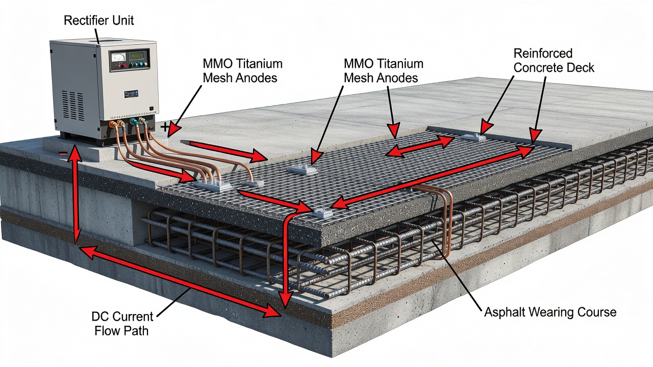
Impressed Current Cathodic Protection (ICCP) is an active electrochemical corrosion control method that forces the reinforcing steel in concrete to become the cathode of an electrochemical cell, thereby suppressing the anodic dissolution (corrosion) reaction. The system applies a small, regulated direct current from an external power source through inert anodes distributed across the concrete surface, through the concrete electrolyte, and to the steel reinforcement. This externally driven current polarizes the steel to a potential where corrosion is thermodynamically impossible or kinetically negligible.
The corrosion cell in reinforced concrete is identical to a battery: it consists of an anodic site (where steel dissolves), a cathodic site (where oxygen reduction occurs), the concrete pore water as the electrolyte (providing ionic conductivity), and the steel itself as the metallic path. Without cathodic protection, the current flowing from the anode equals the current flowing to the cathode (Ia = Ic). When ICCP is applied, the external current from the rectifier supplements the cathodic current, reducing the current that must be supplied by the anodic corrosion reaction. If sufficient external current is applied, the anodic corrosion current approaches zero and corrosion effectively stops.
The electrochemical behavior of steel in concrete is described by the Pourbaix diagram (potential-pH diagram) for iron. For soil-embedded structures, CP aims to shift the steel potential into the immunity region where metallic iron is stable. However, for steel in concrete, achieving the immunity region requires potentials more negative than approximately -900 mV vs Cu/CuSO₄ (CSE) — potentials that can cause hydrogen evolution at the steel surface, leading to loss of bond between steel and concrete and, in prestressed structures, hydrogen embrittlement of high-strength steel. Therefore, ICCP for concrete operates in the passivation region of the Pourbaix diagram rather than the immunity region. The CP current causes electrochemical changes at the steel surface: hydroxyl ions (OH⁻) are generated by the cathodic reduction of water and oxygen, increasing the pH at the steel-concrete interface and repassivating the steel. This repassivation mechanism — the so-called “secondary effect” of CP — is now understood by many researchers to be the dominant mechanism by which ICCP stops corrosion in concrete, rather than the “primary” thermodynamic suppression effect.
ICCP vs Galvanic (Sacrificial) CP — Key Differences:
| Parameter | ICCP | Galvanic CP |
|---|---|---|
| Power source | External DC rectifier (AC mains) | Natural galvanic potential difference |
| Driving voltage | 6–24V (up to 50V max), adjustable | 0.5–1.2V max, fixed |
| Current output | Adjustable, up to 50A per system | Limited, 0.5–50 mA/m² steel |
| Anode material | Inert (MMO titanium, conductive coating) | Sacrificial (zinc, magnesium, aluminum) |
| Anode consumption | Minimal — <1 g/year per anode | High — anode mass consumed, replaced periodically |
| Design life | 25–75+ years (MMO titanium) | 5–30 years (zinc) |
| Best suited for | Large structures, high current demand, adjustable control | Small structures, localized repairs, no power available |
| Initial cost per m² | $150–$500 (varies by anode type) | $50–$200 |
| Monitoring requirement | Monthly rectifier logs, annual depolarization tests | Periodic potential checks |
| Standards | NACE SP0290 / AMPP SP0216, ISO 12696 | NACE SP0408 (for buried/submerged) |
The ICCP current produces two distinct effects. The primary electrokinetic effect shifts the rates of the anodic and cathodic reactions. With sufficient current, the steel potential shifts to a value where the anodic dissolution rate is reduced by a factor of 10,000 or more. The secondary electrochemical effect generates hydroxyl ions at the steel surface through cathodic reactions: O₂ + 2H₂O + 4e⁻ → 4OH⁻ (oxygen reduction) and 2H₂O + 2e⁻ → H₂ + 2OH⁻ (water reduction at more negative potentials). These hydroxyl ions increase the local pH, restoring the passive film that protects steel in alkaline concrete. Additionally, the applied DC current causes electromigration of chloride ions away from the steel toward the external anodes, gradually reducing the chloride concentration at the steel surface over time. This multi-mechanism action explains why ICCP is effective even in concrete with very high chloride content where other repair methods fail.
Hybrid CP (HCP) combines both ICCP and galvanic protection in a two-phase approach. In the first phase, an impressed current is applied at elevated levels (typically 20–60 mA/m² for 2–8 weeks, delivering charge densities of 50–500 kC/m²) to restore the steel’s passive layer. The power source is then disconnected, and galvanic anodes (typically zinc or aluminum alloys) maintain passivity at much lower current densities (0.2–2 mA/m² as specified in ISO 12696 for cathodic prevention). HCP is a relatively recent development that capitalizes on the high current capacity of ICCP for initial passivation combined with the low-maintenance nature of galvanic systems for long-term protection. The ICCP phase of HCP typically uses MMO titanium anodes, which remain in place as galvanic anodes during the second phase, connected to the steel through a resistor to limit current output.
An ICCP system for reinforced concrete comprises six major components that work together to deliver controlled current to the steel reinforcement. Each component must be properly designed, installed, and maintained to achieve the required 25–75+ year service life.
DC Power Source (Transformer-Rectifier / Power Supply Unit): The rectifier converts alternating current (AC) from the mains supply to regulated direct current (DC). Rectifier specifications for concrete ICCP typically include: output voltage range of 0–24V DC (with a minimum of 15–25% headroom above the calculated design voltage to accommodate future increases in concrete resistivity or anode aging), output current capacity of 5–50A per system (depending on the protected steel surface area and required current density), and constant current control mode with constant-voltage overcurrent protection. The rectifier must include instant-off capability (interruption of current within 0.1–0.5 seconds for depolarization measurements), surge protection rated for 500 joules minimum, operating temperature rating of 45°C ambient, and NEMA 3R or 4X enclosure rating for outdoor installation. Rectifier types include tap-set (manual adjustment of output via transformer taps), thyristor-controlled (silicon-controlled rectifier for automatic regulation), variac (variable auto-transformer), and switch-mode (high-frequency switching with digital control). Modern rectifiers incorporate the Transformer Rectifier Integration Module (TRIM) by Vector Corrosion or equivalent — a universal control and monitoring interface that provides remote access via GSM, Ethernet, or SCADA integration, data logging of current, voltage, and potential readings, alarm notification for system faults, and automatic instant-off interruption for depolarization testing.
Anode System: The anode array distributes current from the rectifier positive terminal across the concrete surface. Anode types are detailed in the next section. The anode system must provide uniform current distribution to ensure all areas of the steel reinforcement achieve adequate polarization while avoiding excessive current density that could cause acidification of the anode-concrete interface (anode current density limit of approximately 110 mA/m² of concrete surface — above this threshold, the oxidation of water at the anode generates H⁺ ions that lower the pH, potentially damaging the concrete matrix adjacent to the anode). Anode system design includes calculation of total anode length or area based on the current demand and the rated output of the specific anode material. For MMO titanium ribbon anodes in concrete, the standard current ratings are: 10 mm wide ribbon — 2.8 mA/m, 12.7 mm ribbon — 3.5 mA/m, 19.05 mm ribbon — 5.28 mA/m, and 25.4 mm ribbon — 7.0 mA/m. For MMO titanium mesh anodes: standard rating 16 mA/m² (1.5 mA/ft²), medium rating 22 mA/m² (2.1 mA/ft²), and heavy rating 32 mA/m² (3.0 mA/ft²) of anode surface area.
Reinforcing Steel (Cathode): The steel reinforcement is connected to the negative terminal of the rectifier and functions as the cathode of the ICCP circuit. The steel must be electrically continuous — all bars, stirrups, ties, and mesh must be interconnected with resistance less than 1 ohm between any two points. Continuity testing per ASTM specifications is performed during installation by measuring resistance between multiple points on the reinforcement cage or mat. If continuity cannot be verified (common in structures with lapped bars without mechanical connections or in older construction with discontinuous reinforcement), supplementary continuity bonds must be installed by exposing the reinforcement at selected locations and welding or mechanically connecting copper cables. In prestressed concrete, special care is required because the prestressing steel is at a high stress level and may be susceptible to hydrogen embrittlement if polarized beyond -900 mV vs Ag/AgCl/0.5M KCl (the overprotection limit specified in ISO 12696). For prestressed structures, ICCP design typically includes additional reference electrodes at critical locations and redundant monitoring to ensure the potential never exceeds this limit.
Reference Electrodes: Permanently installed reference electrodes are the essential monitoring elements that measure the polarization potential of the steel reinforcement. The standard reference electrode for concrete ICCP is the silver/silver chloride (Ag/AgCl/0.5M KCl) electrode, which provides a stable, reproducible potential over the life of the system. Other types include copper/copper sulfate (Cu/CuSO₄ or CSE) for use where the concrete is in contact with soil, and zinc reference electrodes for long-term stability in buried applications. NACE SP0290 recommends a minimum of 2–4 reference electrodes per protection zone, positioned at locations representative of the structure’s exposure conditions — typically at mid-span of bridge decks, at column bases in substructures, and at locations with highest predicted chloride concentration. The reference electrodes must be installed in access tubes or embedded directly in the concrete during construction or retrofit. They must be periodically verified against a portable reference electrode (accuracy check) to confirm they have not drifted beyond ±10 mV of their original calibration. Drift beyond this tolerance requires replacement or recalibration. Accuracy of reference electrode readings directly impacts the validity of depolarization test results used to verify protection per the 100 mV criterion.
Wiring and Junction Boxes: The wiring system connects the rectifier to the anode distribution network (positive circuit) and to the steel reinforcement (negative circuit), with junction boxes providing accessible test points for voltage, current, and potential measurements. Each protection zone must have dedicated positive and negative wiring. The wiring is color-coded — typically red for positive (anode circuit) and black or white for negative (steel circuit) — and installed in labeled conduits to prevent accidental cross-connection during maintenance. Junction boxes contain shunt resistors for current measurement (calibrated to provide 1 mV per amp or equivalent reading), test terminals for reference electrode potential readings, and disconnect switches for isolating individual zones. The wire-to-anode connection resistance must not exceed 0.004 ohms (4 milliohms) to prevent localized overheating and voltage drop that reduces system efficiency. All splices in the positive circuit wiring must be avoided between the junction box and the anode — continuous wire runs are required from the junction box to the first anode connection point.
Cementitious Overlay or Grout: For MMO titanium mesh anodes embedded in bridge deck overlays, the overlay material is typically a latex-modified concrete, microsilica concrete, or polymer-modified cementitious mortar applied to a minimum thickness of 40–75 mm over the anode mesh. The overlay serves as the physical environment for the ionic current path from the anode to the concrete substrate and the reinforcing steel below. The overlay must have controlled resistivity (typically 10–50 kΩ·cm) and sufficient bond strength to the existing concrete substrate (minimum 1.0 MPa per ASTM C1583 pull-off testing). For ribbon anodes grouted into saw-cut slots, the grout is a conductive cementitious or polymer-modified material that provides intimate electrical contact between the titanium ribbon and the surrounding concrete.
Four primary anode types are used in ICCP systems for concrete structures. The selection of anode type depends on the structural element being protected (deck, column, soffit, abutment), the required current density, access for installation, concrete surface preparation requirements, and design life targets.
MMO Titanium Mesh: Mixed Metal Oxide (MMO) coated titanium mesh is the most widely specified anode for ICCP on bridge decks and large horizontal surfaces. The substrate is expanded titanium sheet manufactured from ASTM B265 Grade 1 or Grade 2 titanium — selected for its excellent corrosion resistance in the anodic environment and its ability to form a stable oxide layer. The MMO coating consists of a sintered mixture of noble metal oxides — iridium oxide (IrO₂) and tantalum oxide (Ta₂O₅) for oxygen evolution environments (the standard for concrete, where the primary anodic reaction is water oxidation: 2H₂O → O₂ + 4H⁺ + 4e⁻), or ruthenium oxide (RuO₂) and iridium oxide (IrO₂) for chlorine evolution environments (seawater exposure where chloride oxidation: 2Cl⁻ → Cl₂ + 2e⁻ predominates). The coating is applied by thermal decomposition (painting the titanium substrate with a solution of metal chloride salts in organic solvents, then heating to 350–500°C to decompose the salts into the oxide layers) in multiple coats to achieve the specified coating loading.
| Anode Type | Current Rating | Typical Spacing | Design Life | Best Application |
|---|---|---|---|---|
| MMO Ti mesh (standard) | 16 mA/m² (1.5 mA/ft²) | 260–500 mm spacing | 50–75+ years | Bridge decks, plaza decks |
| MMO Ti mesh (heavy) | 32 mA/m² (3.0 mA/ft²) | 200–350 mm spacing | 50–75+ years | High current demand zones |
| MMO Ti ribbon 10 mm | 2.8 mA/m | 200–400 mm centers | 50+ years | Columns, walls, soffits |
| MMO Ti ribbon 25 mm | 7.0 mA/m | 200–400 mm centers | 50+ years | Larger substructure areas |
| Conductive carbon paint | Varies by system | 150–300 mm anode spacing | 15–25 years | Vertical surfaces, complex geometry |
| Arc-sprayed zinc | Varies by system | Continuous coating | 10–20 years | Substructure, tidal zones |
| Conductive ceramic | Up to 35 mA/m² | Custom | 25–50 years | Severe environments |
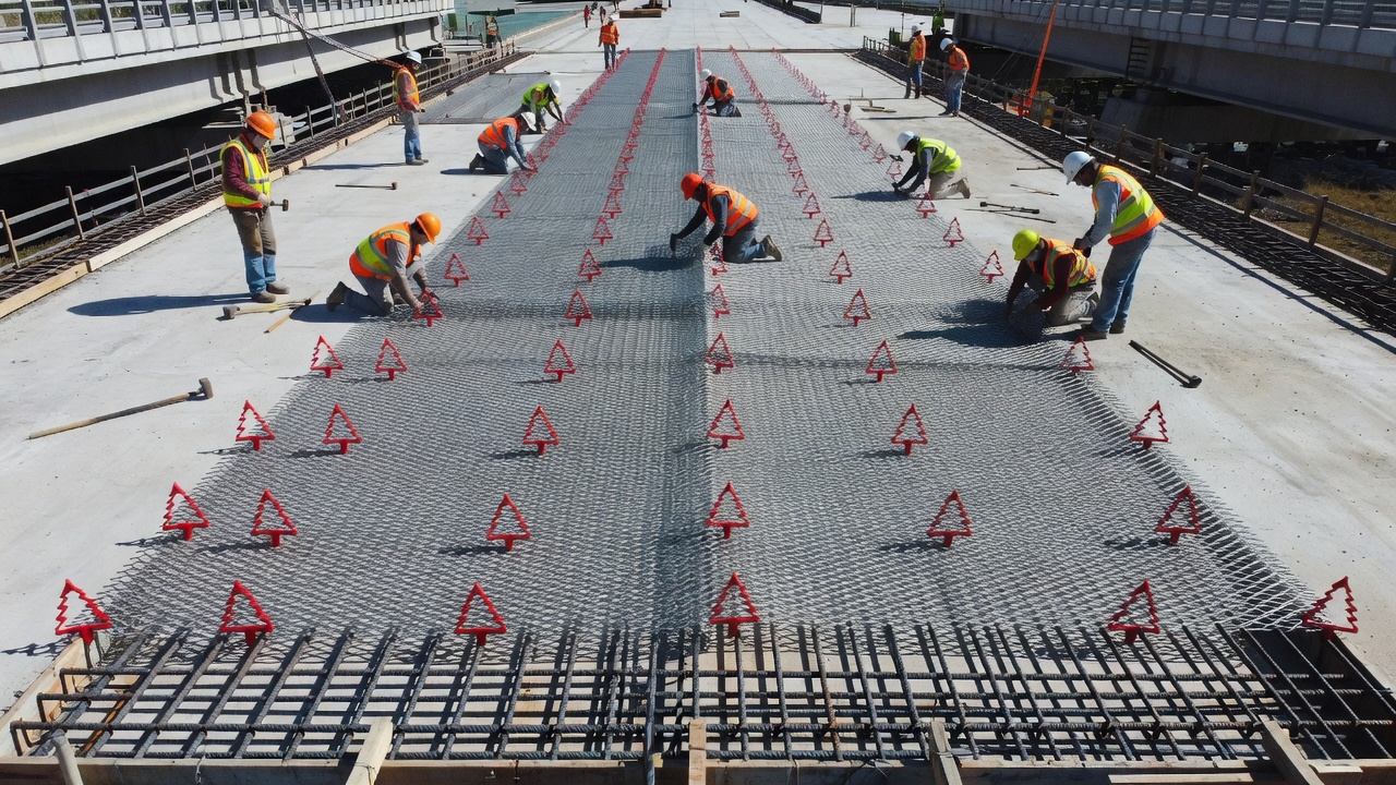
MMO titanium mesh is installed by unrolling the mesh over the prepared concrete surface, securing it with plastic “Christmas tree” fasteners or stainless steel pins at 300–600 mm spacing, then overlapping adjacent mesh sheets by 50–100 mm with the overlaps tied or spot-welded to ensure electrical continuity. Conductor bars (perforated titanium strips or stainless steel bars) are placed perpendicular to the mesh orientation at intervals of 3–6 meters to collect current from the rectifier feeders and distribute it to the mesh. The mesh is then covered with the cementitious overlay (40–75 mm minimum thickness). The mesh opening size is typically 40–100 mm diamond pattern, providing approximately 40–60% open area for overlay penetration and bond with the substrate.
MMO Titanium Ribbon: Ribbon anodes are 10–25 mm wide strips cut from MMO-coated titanium sheet, installed into narrow saw-cut slots (typically 12 mm wide × 20 mm deep) in the concrete surface and backfilled with a conductive cementitious grout or carbon-filled polymer. The ribbon is connected longitudinally to a continuous conductor bar or connected at intervals to transverse feeder bars running in deeper slots. Ribbon anodes are used when an overlay is impractical — for columns, pier caps, walls, and soffit surfaces where adding 40–75 mm of overlay would encroach on clearance envelopes, add excessive dead load, or interfere with architectural features. The saw-cut installation method produces less construction debris than overlay placement and can be completed in phases on partially occupied structures. The spacing between adjacent ribbon slots is calculated based on current demand per square meter of concrete surface — typical spacing is 200–400 mm center-to-center for standard current requirements. The grout must achieve a bond strength of minimum 1.0 MPa and a resistivity compatible with the existing concrete (±20% of substrate resistivity). Ribbon anodes may also be installed in concrete overlay for new construction — the ribbon is laid on the substrate before the overlay is placed, providing a thinner profile than mesh.
Conductive Carbon Paint (Conductive Anode System — CAS): Conductive polymer coatings are solvent-based or water-based paints loaded with conductive carbon black and applied directly to the concrete surface in multiple coats to a total dry film thickness of 10–15 mils (250–380 μm) . The coating system includes a primary anode conductor — typically platinum-niobium-copper core wire, 0.031 inches (0.79 mm) diameter — installed in shallow saw slots (3/8 to 1/2 inch wide × 3/4 inch deep) filled with conductive polymer grout. The CAS system distributes current from the primary anode wire through the carbon-loaded paint to the surrounding concrete. Advantages include applicability to complex geometries (curved surfaces, arches, columns with fluted profiles), minimal added dead load, and ease of repair — the coating can be spot-repaired by cleaning the surface and reapplying paint. The primary disadvantage is limited service life of 15–25 years — the carbon-loaded polymer can degrade under UV exposure, and the anode-concrete interface can become acidic over time due to water oxidation at the anode, causing the coating to delaminate. CAS is rated for current densities up to approximately 35 mA/m² of concrete surface. It is suitable for land structures exposed to deicing salts but is not recommended for aggressive marine environments where saltwater spray accelerates degradation.
Arc-Sprayed Zinc (Thermal Sprayed Zinc — TSZ): This anode type consists of a 20-mil (500 μm) thick layer of 99% pure zinc applied to a sandblasted concrete surface using electric arc spraying — two zinc wires are fed into an electric arc that melts the metal, and compressed air atomizes the molten metal onto the prepared surface. The coating is applied in multiple overlapping passes to achieve uniform thickness. Current is distributed to the zinc coating through titanium distributor bars (typically 12.7 mm wide × 1 mm thick, coated with mixed metal oxide) that are embedded in the zinc layer or attached to the concrete surface before spraying. The zinc layer itself has relatively high electrical resistivity, and the titanium distributor bars must be spaced at 3–6 meter intervals to ensure adequate current distribution across large areas. Arc-sprayed zinc has been used extensively on bridge substructures in Florida, Virginia, and Oregon, with cost ranging from $12/ft² to $41/ft² across multiple contracts on the Howard Frankland Bridge (1992–2009). Service life is typically 10–20 years before re-application is needed, as the zinc coating corrodes sacrificially and the oxide layer that forms can increase contact resistance. Humectants (moisture-attracting chemicals such as lithium bromide) can be applied to the zinc surface to maintain moisture at the anode-concrete interface, improving current output by up to 7× compared to dry zinc coatings.
Conductive Ceramic Anodes: Conductive ceramic anodes consist of fired ceramic tiles with conductive oxide coatings (typically tin oxide doped with antimony or indium oxide) bonded to the concrete surface. They offer high current capacity (up to 35 mA/m²) and long service life (25–50 years) in severe environments. However, they are more expensive than MMO titanium and carbon-based alternatives and are rarely specified in North America — most applications are in European bridge and tunnel projects.
Anode Selection Criteria Summary:
| Factor | MMO Ti Mesh | MMO Ti Ribbon | CAS Paint | Arc-Sprayed Zn | Ceramic |
|---|---|---|---|---|---|
| Horizontal surfaces | Excellent | Good | Poor | Fair | Poor |
| Vertical surfaces | Poor | Good | Excellent | Excellent | Fair |
| Complex geometry | Poor | Poor | Excellent | Good | Poor |
| Design life >50 years | Yes | Yes | No | No | Limited |
| Cost per m² | Medium-High | Medium | Low-Medium | Medium | High |
| Maintenance requirement | Low | Low | Medium | High | Low |
| In-service accessibility | Overlay required | Surface accessible | Surface accessible | Surface accessible | Surface accessible |
The rectifier is the heart of the ICCP system, converting AC mains power to regulated DC output and providing the driving voltage that polarizes the steel reinforcement. Modern ICCP rectifiers incorporate sophisticated control, monitoring, and communication capabilities that enable remote system management and automated depolarization testing.
Rectifier Types:
| Type | Control Method | Typical Efficiency | Cost | Best Application |
|---|---|---|---|---|
| Tap-set | Manual transformer tap adjustment | 80–85% | Low | Small systems, low maintenance |
| Thyristor (SCR) | Phase-angle firing of silicon-controlled rectifiers | 85–92% | Medium | Medium-to-large systems, constant current |
| Variac | Variable auto-transformer | 85–90% | Medium | Research, adjustable needs |
| Switch-mode | High-frequency PWM switching (10–100 kHz) | 90–96% | Medium-High | Large systems, remote monitoring |
Tap-set rectifiers are the simplest and most robust type. The output voltage is adjusted by selecting different taps on the transformer secondary winding, typically providing 4–8 discrete voltage steps. Output current is not regulated — it varies with the load resistance (concrete resistivity, anode condition). Tap-set rectifiers are suitable for small systems with stable concrete conditions where infrequent adjustment is required. Thyristor-controlled (SCR) rectifiers use phase-angle firing of silicon-controlled rectifiers on the AC input to the transformer, providing continuous adjustment from 0–100% output. A feedback loop maintains constant current output regardless of changes in load resistance — this is the preferred control mode for ICCP because the required current density (mA/m² of steel) is the primary design parameter. If concrete resistivity increases (e.g., during dry summer conditions), the rectifier automatically increases voltage to maintain the set current. If resistivity decreases (e.g., during wet winter with deicing salts), voltage automatically decreases.
Switch-mode rectifiers use high-frequency pulse-width modulation (PWM) at 10–100 kHz to regulate output, eliminating the heavy 50/60 Hz transformer. They achieve 90–96% efficiency compared to 80–85% for traditional thyristor rectifiers. The weight reduction (60–80% lighter) and efficiency improvement are significant for large bridge ICCP systems where multiple rectifiers (one per zone) are housed in cabinets or bunkers. Switch-mode rectifiers incorporate digital control with programmable ramp-up times (to avoid sudden current surges that could damage the anode-concrete interface), soft-start capabilities, and automated instant-off interruption sequences.
Control Modes: ICCP systems operate in constant current mode as the primary control strategy. The output current is set to the design value (typically 10–20 mA/m² of steel surface area for bridge decks) and the rectifier adjusts voltage as needed to maintain that current. Constant voltage mode is used as a backup or for initial system startup — voltage is set to the calculated design value and current is allowed to vary with load changes. Constant potential mode (also called potentiostatic control) maintains the steel potential at a set value relative to a reference electrode — this is the most sophisticated control mode and is used for prestressed concrete structures where overprotection must be strictly avoided. The reference electrode potential is fed back to the rectifier controller, which adjusts current output to maintain the steel at the target potential (typically -700 to -800 mV vs Ag/AgCl).
Remote Monitoring and Control (SCADA Integration): Modern ICCP rectifiers are equipped with communication modules that enable full remote system management. The Transformer Rectifier Integration Module (TRIM) from Vector Corrosion is a universal add-on that provides: real-time monitoring of voltage, current, and reference electrode potentials; automated instant-off interruption at programmable intervals (typically every 24 hours for 1–4 seconds to capture instant-off potentials, plus a full 24-hour depolarization test annually); data logging with time-stamped history of all system parameters; alarm notification for high/low current events, rectifier faults, ground faults, and reference electrode drift; remote adjustment of current output set-point; and web-based interface through GSM, Ethernet, or SCADA network. The integration of remote monitoring with automated depolarization testing is a significant advancement — it eliminates the need for field personnel to travel to each rectifier location for periodic testing and provides a continuous record of system performance that can be reviewed for compliance with NACE SP0290 criteria.
Rectifier Sizing: The rectifier must be sized with adequate capacity to meet the worst-case current demand of the protected zone. The design process involves: calculating the total steel surface area in the zone (this requires review of reinforcement drawings, bar sizing, and spacing), multiplying by the design current density (typically 2–20 mA/m²), adding a safety factor of 1.25–1.50 for future increases in demand, calculating the voltage required to drive this current through the circuit resistance (concrete resistivity × anode spacing + wiring resistance + connection resistances), and adding a voltage headroom of 15–25% above the calculated value. For a typical bridge deck zone of 1,000 m² steel surface at 15 mA/m², the current demand is 15A. With a calculated voltage requirement of 12V based on concrete resistivity of 20 kΩ·cm and anode spacing of 300 mm, the rectifier specification would be: 20A minimum at 15V, constant current mode, with remote monitoring.
Monitoring is essential to verify that the ICCP system is providing effective protection and to detect problems — rectifier faults, anode deterioration, reference electrode drift, or wiring issues — before they compromise the protection of the steel reinforcement. NACE SP0290 defines the monitoring requirements for ICCP on atmospherically exposed concrete.
Potential Measurements: The fundamental monitoring measurement is the structure-to-electrolyte potential — the voltage difference between the steel reinforcement and a reference electrode placed on or embedded in the concrete. This measurement is expressed in millivolts (mV) relative to the reference electrode type (Ag/AgCl/0.5M KCl or Cu/CuSO₄). The measurement is taken under three conditions: native (free corrosion) potential — the potential before CP is applied, indicating whether corrosion is active; instant-off potential — the potential measured within 0.1–0.5 seconds after the CP current is interrupted, representing the polarized potential of the steel without the IR drop error caused by current flow through the concrete resistance; and depolarized (decay) potential — the potential measured after the CP current has been off for 24 hours (or longer for massive structures), representing the natural corrosion potential of the steel as the polarization dissipates.
The 100 mV Polarization Decay Criterion (NACE SP0290 / AMPP SP0216): The standard criterion for effective CP is that the steel reinforcement must exhibit a minimum polarization decay of 100 mV within 24 hours (or a longer period with appropriate justification) from the instant-off potential. The 100 mV criterion is preferred over absolute potential criteria because it is independent of the reference electrode type (it works with Ag/AgCl, CSE, or zinc electrodes), it is independent of the native corrosion potential of the steel (which can vary from -100 mV for passive steel to -600 mV for actively corroding steel), and it accounts for the repassivation effect of CP rather than just thermodynamic suppression. The polarization decay represents the shift in steel potential caused by the CP current — if when the current is switched off the potential decays by at least 100 mV, it proves that the CP was achieving at least 100 mV of polarization. The 100 mV criterion has been correlated with a corrosion rate reduction of at least one order of magnitude (90% reduction) through laboratory studies and field validation.

Depolarization Testing Procedure: The test is performed by interrupting the CP current (either manually or using the rectifier’s remote instant-off function), recording the instant-off potential within 0.5 seconds, then recording the potential at intervals over the next 24 hours — typically at 1, 2, 4, 8, 12, and 24 hours. The potential decay at each interval is calculated as the difference between the potential at that time and the instant-off potential. A total decay of 100 mV or more at any time within the 24-hour period (or longer) satisfies the criterion. The potential decay curve shape provides additional diagnostic information: a rapid initial decay (steep slope in the first 1–4 hours) indicates that a large portion of the polarization was due to concentration effects at the steel surface, which is normal for well-polarized systems. A shallow, slow decay (gradual slope over 12–24 hours) indicates that the CP has achieved significant chemical changes at the steel-concrete interface (the secondary effect of repassivation), which is the most beneficial form of polarization.
Current Density Monitoring: The operating current density at the steel surface must be measured and logged to verify it remains within the design range. ISO 12696 states that CP for most concrete structures operates at 2–20 mA/m² of steel surface area. For cathodic prevention (protecting steel that has not yet initiated corrosion), the required current density is 0.2–2 mA/m². The current density is calculated by dividing the total zone current (measured at the rectifier or through shunt resistors in junction boxes) by the estimated steel surface area in the zone. Current density values below the design range suggest the system is under-protecting the steel; values significantly above the design range may indicate an electrical short or excessive current demand that could lead to premature anode consumption or concrete damage at the anode-concrete interface. The upper limit at the anode-concrete interface is approximately 110 mA/m² — above this, acidification from water oxidation can cause debonding of the overlay or grout.
Overprotection Limits: For ordinary reinforcing steel, the instant-off potential must be maintained more positive than -900 mV vs Ag/AgCl/0.5M KCl (approximately -1,100 mV vs CSE) to prevent hydrogen evolution at the steel surface. For prestressing steel, the limit is stricter: instant-off potentials must not exceed -900 mV vs Ag/AgCl/0.5M KCl (ISO 12696). Potentials more negative than this value can cause atomic hydrogen to form at the steel surface and diffuse into the high-strength steel, leading to hydrogen embrittlement — a catastrophic, brittle failure mechanism with no warning. Prestressed concrete ICCP systems must include redundant reference electrodes, automated overpotential alarms on the rectifier, and rectifier output limits that prevent the current from exceeding the level required to maintain potentials above the overprotection threshold.
Concrete Resistivity Monitoring: Concrete resistivity is an important parameter that affects both the performance of the CP system (resistivity determines the voltage required to drive the design current) and the corrosion rate of unprotected steel (low resistivity supports high corrosion rates). Resistivity can be measured using embedded 2-probe or 4-probe resistivity sensors per ASTM G57 methodology. Typical concrete resistivity values: saturated with chlorides (marine immersion zone) — 0.9–1.5 kΩ·cm; saturated with deicing salts (bridge deck winter conditions) — 2–10 kΩ·cm; moist concrete — 10–50 kΩ·cm; dry concrete (interior parking structure, dry climate) — 50–200+ kΩ·cm. When concrete resistivity increases significantly (e.g., dry summer conditions), the CP system voltage must increase to maintain the set current. If the rectifier is already at maximum voltage, the current output will drop and the steel may not achieve adequate polarization. This seasonal variation is normal and is accounted for in the design headroom of 15–25% voltage capacity.
NACE SP0290 (now maintained by AMPP as SP0216) — “Standard Practice — Impressed Current Cathodic Protection of Reinforcing Steel in Atmospherically Exposed Concrete Structures” — is the governing standard for ICCP system design, installation, operation, and monitoring. The standard was first published by NACE International in 1990, updated in 2007 and most recently in 2019 (Item No. 21043, ISBN 1-57590-103-X).
Applicability: SP0290 covers ICCP for reinforced concrete structures exposed to atmospheric conditions — bridge decks, parking garages, building facades, piers above the splash zone. For buried or submerged concrete structures, NACE SP0408 (Cathodic Protection of Reinforcing Steel in Buried or Submerged Concrete Structures) applies. For international projects, ISO 12696:2016 (Cathodic Protection of Steel in Concrete) provides equivalent criteria with some differences in reference electrode conventions and specific limit values.
Subject Matter Expert (SME) Requirements: The standard requires that the person responsible for design, monitoring, and interpretation of ICCP systems shall be certified to NACE CP Level 4 (Cathodic Protection Specialist) or have equivalent national or international qualification and experience. The minimum experience requirement for the SME is three years of documented cathodic protection work with concrete structures.
Protection Criteria (Section 5 of SP0290): The primary criterion is the 100 mV polarization decay within a time period not exceeding 24 hours (or longer if justified by the characteristics of the structure and documented in the project records). The polarization is defined as the net change in potential measured between the structure and a reference electrode upon interruption of the CP current, excluding any IR drop contributions. The standard permits alternative criteria — the 100 mV polarization shift (potential difference between the native potential and the polarized potential with the CP on, corrected for IR drop) or the absolute potential criterion (-850 mV vs CSE for steel in soil-simulating environments) — but the 100 mV decay is the most commonly specified and accepted method for concrete structures because it automatically excludes IR drop.
Overprotection Limits (Section 6): SP0290 warns against applying excessive CP current that could cause: hydrogen embrittlement of prestressing steel (limits instant-off potentials to -900 mV vs Ag/AgCl/0.5M KCl), loss of bond between steel and concrete, or damage to the concrete matrix. The standard requires that if any of these conditions could occur, the CP system must be designed with redundant monitoring, automatic current limitation, and fail-safe features.
Monitoring Requirements (Section 7): The standard specifies: monthly inspection of power sources — verify output voltage and current are within ±10% of design values, check indicator lights and meters, log all readings; annual surveys — measure structure-to-electrolyte potentials at all reference electrodes, perform depolarization tests to verify the 100 mV criterion, inspect junction boxes and wiring; and thorough inspections at intervals not exceeding 3–5 years — verify reference electrode accuracy against portable reference electrodes, inspect anode condition (overlay delamination survey, coating adhesion testing, grout integrity), check for electrical shorts, ground connections, meter accuracy, rectifier efficiency, and circuit resistance.
Documentation Requirements (Section 8): SP0290 requires complete documentation including: as-built drawings showing locations of all system components (rectifier, anodes, reference electrodes, junction boxes, wiring conduits); design calculations showing steel surface area per zone, required current density, voltage requirements, anode sizing; initial test results including native potentials, instant-off potentials after first activation, and current density distribution; periodic survey reports with all potential measurements, depolarization curves, and rectifier log data; and maintenance records for all repairs, adjustments, and component replacements.
Other Applicable Standards:
| Standard | Title | Key Coverage |
|---|---|---|
| NACE SP0290-2019 (AMPP SP0216) | ICCP of Reinforcing Steel in Atmospherically Exposed Concrete Structures | Design, installation, monitoring of ICCP |
| NACE SP0408-2019 | CP of Reinforcing Steel in Buried or Submerged Concrete Structures | Submerged/buried concrete CP |
| ISO 12696:2016 | Cathodic Protection of Steel in Concrete | International CP criteria for concrete |
| ASTM C876-15 | Standard Test Method for Corrosion Potentials of Uncoated Reinforcing Steel in Concrete | Half-cell potential mapping |
| ASTM G57-06(2012) | Field Measurement of Soil Resistivity Using Wenner Four-Electrode Method | Resistivity measurement for CP design |
| NACE TM0294-2018 | Testing of Embeddable Reference Electrodes for Concrete | Qualification testing for permanent reference electrodes |
Regular inspection is critical to ensure that ICCP systems continue to provide effective corrosion protection throughout their design life. The Virginia DOT study (VTRC 07-R35) documented that many of the 12 ICCP systems installed on Virginia bridges in the 1980s and 1990s had failed or were operating sub-optimally because inspection and maintenance had been neglected after research projects concluded.
Monthly Inspection (Rectifier Check): The rectifier should be visited monthly to verify: output voltage within ±10% of set-point; output current within ±10% of set-point; indicator lights and digital display functioning correctly; no error codes or alarm conditions displayed; no signs of physical damage, water ingress, or vermin infestation in the rectifier cabinet; and all circuit breakers and fuses in the closed position. Readings are recorded on a system log sheet (paper or digital). If any reading deviates by more than 10% from the design value, the cause must be investigated — common causes include: concrete drying (increased resistivity, lower current), concrete wetting with deicing salts (decreased resistivity, higher current), anode deterioration (increased resistance, lower current), wiring damage, or rectifier component failure.
Annual Inspection (Performance Verification): The annual survey must include: measurement of instant-off potentials at all permanent reference electrodes — the current is interrupted (manually or via the rectifier’s remote function) and potential recorded within 0.5 seconds; a 24-hour depolarization test — the current remains off for 24 hours (or longer) with potential measurements recorded at 1, 2, 4, 8, 12, and 24 hours to construct a depolarization curve; verification that the 100 mV polarization decay criterion is satisfied; if the criterion is not met, investigation of the cause (insufficient current, anode disconnection, reference electrode drift, or increased corrosion activity requiring higher current); and measurement of reference electrode accuracy by comparing permanent electrode readings to a portable reference electrode placed adjacent to each permanent electrode (difference should be less than ±10 mV).

Every 3–5 Years (Comprehensive System Inspection): The full system inspection includes: anode condition assessment — for MMO mesh in overlays, the overlay is sounded for delamination (chain drag or hammer sounding), and core samples are taken from representative locations (minimum 2 per zone) for visual inspection of the anode-concrete interface; for conductive coatings, adhesion testing per ASTM D3359 is performed, and any areas of blistering, peeling, or discoloration are quantified; for arc-sprayed zinc, thickness is measured using magnetic gauges (minimum 15 mils remaining), and the zinc surface is inspected for oxide buildup. Wiring system check — resistance measurements at all junction boxes verify positive and negative circuit continuity; all connections are inspected for corrosion or loose terminations; ground fault testing verifies the negative circuit is not grounded (resistance to ground >1 MΩ). Rectifier efficiency test — AC input power and DC output power are measured to calculate efficiency; if efficiency has dropped below 80% for tap-set or thyristor units or below 88% for switch-mode units, the rectifier may require service or replacement. Reference electrode replacement or recalibration — any permanent reference electrode that has drifted more than ±20 mV from its original calibration should be replaced. Spare parts inventory — fuses, surge protectors, and rectifier control boards should be verified available.
Common ICCP System Failures (from Virginia DOT Field Survey): The VTRC 07-R35 study documented the following failure modes across 12 ICCP systems on Virginia bridges: power disconnected but never restored (Route 99 Over Peak Creek — system disconnected from power pole and never reconnected; Route 15 Over Willis River — power disconnected for unknown reasons, structure replaced entirely in 2006); missing fuses (Zone 3 on Smart Road Bridge operated for years with zero current due to a missing fuse that was never detected because monthly monitoring was not performed); controller card failures (I-64 WBL Hampton Roads Bridge-Tunnel system never successfully energized after installation — controller card issues, short circuits, rectifier troubles, and grounding problems were theorized but never resolved on the 400,000+ ft² deck); LCD meter failures (I-64 EBL over 13th View Street — LCD meter nonfunctional, system operating blind without verification of output); lightning damage and vandalism causing rectifier failures.
Registration and Tracking: Every ICCP system should be registered in the agency’s asset management system with: unique identifier, installation date, design life, zone configuration, rectifier model and serial number, key performance parameters (design current density, anode type, reference electrode locations), and current inspection status. This registration ensures that systems are not “orphaned” when original installation contracts expire or when responsible personnel rotate to new assignments.
Bridge decks are the most common application of ICCP for concrete structures — they are directly exposed to deicing salts, traffic wear, and freeze-thaw cycles, making them the most corrosion-vulnerable element of most bridge structures.
Historical Development: The first bridge deck ICCP system was installed by the California Department of Transportation (Caltrans) on the Sly Park Road Bridge in June 1973. The system used a conductive asphalt overlay with coke breeze (carbon aggregate) as the anode. After several years of operation, the protected section of the deck showed no new delaminations (except in areas that had been epoxy-injected for crack repair prior to CP installation), while the unprotected section of the same deck continued to deteriorate with new spalls and delaminations appearing each year. This demonstration conclusively proved that ICCP could stop ongoing corrosion in chloride-contaminated bridge decks.
Battelle Survey (1988–1989): By 1988, more than 275 bridge structures in the USA and Canada had been equipped with cathodic protection systems, covering a total concrete surface area of approximately 9,000,000 ft² (840,000 m²) . Most bridges were 20–35 years old when CP was applied. 90% of the systems were in deicing salt regions and 10% in marine environments. The survey found that 80% of CP systems were functioning satisfactorily, with the majority using ICCP technology. The 20% non-functional rate was primarily attributed to lack of monitoring and maintenance rather than fundamental technology failures.
Major Bridge Deck ICCP Installations:
Clyde Tunnel, Glasgow, Scotland: 2,460 ft (750 m) long, 30 ft (9 m) diameter twin-bore tunnel under the River Clyde. ICCP specification required a 25-year operating life. The system used MMO titanium mesh in a concrete overlay for the tunnel walls and MMO titanium ribbon anodes grouted into slots for the tunnel roof (soffit). The tunnel was divided into 187 independent protection zones, each approximately 4 ft (1.2 m) wide, corresponding to the tunnel’s cast-iron segmental liner joints. Each zone was powered by its own rectifier with independent control and monitoring. As of a 2015 status report (20 years after installation), the ICCP system was performing as designed and concrete repairs were not needed — the CP had effectively mitigated all further corrosion damage since installation.
Midland Links Motorway Viaducts, UK: Approximately 13 miles (21 km) of elevated dual-carriageway roadways comprising over 1,300 spans, crossbeams, and expansion joints supported by more than 3,600 columns. ICCP was installed on more than 740 individual bridge structures within this complex, making it one of the largest ICCP deployments in the world. The system used MMO titanium ribbon anodes in saw-cut slots for columns and MMO titanium mesh in overlays for deck surfaces. The Midland Links project was pivotal in developing installation techniques for large-scale ICCP — including zoning strategies for multi-element structures, techniques for ensuring electrical continuity across complex reinforcement arrangements, and streamlined monitoring approaches for hundreds of individual zones.
Howard Frankland Bridge, Tampa, Florida: A 3+ mile, 8-lane bridge carrying 180,000 vehicles per day across Tampa Bay, constructed in 1960. Florida DOT has executed a total of 21 CP contracts on this structure cumulatively valued at approximately $15 million. The first contract (1987) installed ICCP on selected pile caps and columns at $25/ft² — this system included remote monitoring capabilities, which was pioneering for its time. Subsequent contracts have used both ICCP (titanium mesh encapsulated in Gunite for columns and struts, issued at $161.50/ft² in 2009) and galvanic systems (arc-sprayed zinc metalizing at $12–41/ft², pile jackets at $42/ft² initially rising to $12,187 per pile by 2009). The bridge remains in full-load service 60+ years after construction, with the CP systems continuously protecting the substructure elements from corrosion in the aggressive marine environment.
Hampton Roads Bridge-Tunnel, Virginia: The original 1958 structure crosses the mouth of the James River with an estimated 400,000+ ft² of deck surface. Rehabilitation in 1998 included a latex-modified concrete overlay containing embedded titanium anode mesh with MMO catalyst for ICCP. Unfortunately, system startup was problematic — the system was never successfully energized due to controller card issues, shorts, and rectifier troubles that were never fully resolved. This case illustrates the importance of thorough testing at system commissioning and the consequences of unresolved startup issues.
Virginia Smart Road Bridge, Blacksburg, Virginia: This structure is notable because the ICCP system was installed during new construction — a rare application of CP on a new bridge rather than as a rehabilitation measure. The 14,000 ft² deck was protected in 5 independent zones using MMO titanium ribbon mesh embedded directly in the original cast-in-place concrete (not an overlay). The system was activated in January 2000 with initial current densities of 5.76–11.03 mA/m² (0.576–1.103 mA/ft²). Measured voltage requirements ranged from 1.38–2.38V initially, increasing to 2.10–3.34V after 16 months, then stabilizing at 1.9–3.3V by 2002. By 2007, Zone 3 was found to have a missing fuse (zero current) and Zone 4 had dropped from 3.34A to 2.12A. The system demonstrated that ICCP can effectively prevent corrosion initiation in new construction, but also highlighted the ongoing monitoring requirement.
Design Parameters for Bridge Deck ICCP:
| Parameter | Typical Range | Notes |
|---|---|---|
| Steel surface current density | 10–20 mA/m² (1–2 mA/ft²) | Based on steel area per m² of deck |
| Concrete surface current density | 0.5–3 mA/m² | Based on plan area of deck |
| Rectifier voltage requirement | 6–24V DC | Depends on concrete resistivity and anode spacing |
| Anode spacing (MMO ribbon) | 200–400 mm | Tighter spacing for higher resistivity |
| Anode spacing (MMO mesh) | 260–500 mm | Mesh opening size affects overlay bond |
| Reference electrodes per zone | 2–4 minimum | NACE SP0290 requirement |
| Zone size | 250–2,500 m² deck area | Limited by voltage drop and current distribution |
| Overlay thickness (mesh anodes) | 40–75 mm | Exclusive of substrate preparation |
| Design life of anode system | 50–75 years | MMO titanium — limited by coating consumption |
The service life of an ICCP system depends on the durability of its components — particularly the anodes, reference electrodes, wiring, and rectifier. Electronic components (rectifiers, controllers, data loggers) are typically the first to fail, not the anodes. A comprehensive service life plan must address both the electrochemical components and the electrical/electronic components.
Anode Service Life:
| Anode Type | Design Life | Field Experience | Failure Mode |
|---|---|---|---|
| MMO titanium mesh | 50–75+ years | >30 years demonstrated (Howard Frankland 1987) | Coating depletion at excessive current density |
| MMO titanium ribbon | 50+ years | >25 years demonstrated (Clyde Tunnel, Midland Links) | Coating depletion, slot grout deterioration |
| Conductive carbon paint (CAS) | 15–25 years | 15–20 years typical (Virginia DOT study) | Acidification at anode, coating delamination |
| Arc-sprayed zinc | 10–20 years | 5–15 years before re-application (Florida DOT) | Zinc consumption, oxide layer formation |
| Conductive ceramic | 25–50 years | Limited field data | Tile fracture, loss of bond |
Key Factors Affecting ICCP Service Life:
Coating depletion rate — MMO coatings on titanium anodes are consumed at a rate proportional to the operating current density. At the design current density (16 mA/m² for standard mesh), the coating consumption rate is less than 1 gram per year per square meter of anode. At higher current densities or if the system is operated at elevated output (due to increased concrete resistivity or rectifier voltage headroom), coating consumption accelerates. The precious metal loading of the coating (typically 5–15 g/m² of IrO₂ + Ta₂O₅) determines the total charge that can be passed before the coating is depleted. Accelerated life testing in Na₂SO₄ or NaCl electrolyte at elevated temperature (60–80°C) and high current density (100–1,000× design value) is used by manufacturers to predict service life.
Fluoride attack on titanium substrate — Titanium is susceptible to corrosion in the presence of fluoride ions (F⁻), which can be present in concrete from contaminated aggregates, certain chemical admixtures, or environments exposed to fluoride-containing chemicals. Fluoride ions attack the protective oxide layer on titanium, leading to rapid localized corrosion of the substrate. If titanium anodes will be exposed to fluoride environments, the MMO coating must provide complete coverage without holidays, and alternative anode materials (e.g., niobium substrate) should be considered.
Cable sealing integrity — The junction between the titanium anode and the copper conductor cable is the most vulnerable point in the anode circuit. Water ingress into this junction creates a galvanic cell between titanium and copper, leading to rapid corrosion of the copper conductor. All anode-to-cable connections must be hermetically sealed with multiple layers of heat-shrink tubing, epoxy potting, and moisture-blocking compounds. Pull testing (100 N minimum), IR testing (insulation resistance >100 MΩ), and hydrostatic pressure testing (for submerged installations) are used to verify cable seal integrity.
Reference electrode drift — Permanent reference electrodes have finite service lives. Ag/AgCl/0.5M KCl electrodes typically last 10–20 years before the internal electrolyte dries out or becomes contaminated. Zinc reference electrodes can last 25+ years in buried applications but can develop a passive oxide layer that increases resistance. Reference electrodes should be verified against a portable standard at each annual inspection, and electrodes that have drifted more than ±20 mV should be replaced.
Rectifier and electronic service life — The rectifier power supply has a typical service life of 15–25 years for electrolytic capacitor-based units (capacitors dry out over time, increasing ripple and reducing efficiency) and 20–30 years for transformer-based units (limited by insulation aging and core saturation). Switch-mode rectifiers with high-frequency transformers have the highest component density and are more susceptible to failure from lightning surges, voltage spikes, and thermal stress. Surge protection devices (rated for 500 joules minimum as specified by NACE) must be verified at each annual inspection and replaced every 5–10 years. Rectifier replacement should be included in the system’s life-cycle cost plan at 20-year intervals.
Concrete overlay service life: For MMO mesh systems embedded in cementitious overlays, the overlay itself has a service life of 15–35 years depending on traffic loading, freeze-thaw exposure, overlay material (latex-modified concrete has the longest field-proven life for bridge decks), and quality of installation. Overlay delamination or wear-through exposes the mesh to direct traffic and mechanical damage, requiring overlay replacement. The overlay replacement cost is significant and can exceed 60% of the total ICCP system cost. However, the MMO anode mesh can be reused after overlay replacement if it has not suffered mechanical damage during overlay removal. This is an important consideration in life-cycle cost analysis.
Life-Cycle Cost Considerations:
| Cost Component | % of Total Life-Cycle Cost | Frequency |
|---|---|---|
| Initial design and installation | 40–60% | Once (year 0) |
| Monthly rectifier inspection | 5–10% | Monthly (12 visits/year) |
| Annual depolarization tests | 3–8% | Annually |
| 3–5 year comprehensive inspections | 5–10% | Every 3–5 years |
| Overlay replacement | 15–25% | Every 20–35 years |
| Rectifier replacement | 5–10% | Every 20–25 years |
| Reference electrode replacement | 2–5% | Every 10–20 years |
| Anode repair/spot replacement | 2–5% | As needed |
Field Performance Statistics (from CONREPNET and US Army Corps of Engineers): The following data compares conventional concrete repair (patch repair without CP) to repair with cathodic protection: after 5 years — 80% of conventional repairs satisfactory vs 85% of CP repairs satisfactory; after 10 years — 30% of conventional repairs satisfactory vs 80% of CP repairs satisfactory; after 25 years — 10% of conventional repairs satisfactory vs 60% of CP repairs satisfactory. The conclusion is clear: CP (including ICCP) provides dramatically better long-term performance than conventional repair for chloride-contaminated structures, with the advantage increasing over time.
ICCP for airport infrastructure is applied primarily to reinforced concrete elements in parking structures, terminal buildings, and ancillary facilities that are exposed to deicing chemicals and marine environments. Airport rigid pavements (runways, taxiways, aprons) are typically jointed plain concrete pavement (JPCC) without continuous reinforcement — the only embedded steel is dowel bars at joints — so ICCP is less commonly specified for airfield pavements per se.
Hartsfield-Jackson Atlanta International Airport — the world’s busiest airport by passenger traffic — references cathodic protection in its Capital Project Standards, requiring anchorage, venting, and cathodic protection for certain buried metallic elements in fuel system and utility infrastructure. Airport parking garages in Atlanta and other major hubs often incorporate ICCP or galvanic CP for concrete decks and ramps exposed to deicing chemicals that are tracked in by vehicles from aircraft deicing pads.
Airport Parking Structures: Multi-level parking garages at airports are among the most corrosion-prone structures in the built environment. They receive deicing chemicals tracked in by passenger vehicles that have been parked in short-term lots near terminals or by airline service vehicles that operate on airfield aprons. Chlorides from deicing fluids (primarily potassium acetate, sodium formate, and ethylene/propylene glycol with additives) penetrate the concrete deck surfaces through joints, cracks, and surface wear. The corrosion risk is exacerbated by the enclosed, humid microclimate typical of enclosed parking structures — high relative humidity (70–95%) and limited air circulation maintain the concrete in a moist condition that supports ion transport and corrosion reactions. ICCP for parking structures typically uses MMO ribbon or conductive carbon paint anode systems, with zoning to match individual deck levels or expansion joint bays. Monitoring is essential because parking structures are occupied by the public and have limited access for inspection without traffic disruption.
Airport Apron and Deicing Pad Infrastructure: While runways and taxiways are unreinforced, aprons and deicing pads sometimes contain steel reinforcement where they have been designed for heavy aircraft loads, and they are exposed to the highest concentrations of deicing chemicals. Deicing fluid collection systems, containment structures, and drain channels in these areas contain reinforced concrete that may benefit from ICCP. The JICA (Japan International Cooperation Agency) airport development reports reference pavement design periods of 20 years and note the importance of corrosion protection for reinforcing steel in airport structures, particularly in coastal airport expansions. The Hong Kong Environmental Impact Assessment for the Hong Kong International Airport expansion references cathodic protection for runway infrastructure in compliance with ICAO requirements for safe operation and infrastructure durability.
Marine Airport and Coastal Infrastructure: The Korea Maritime and Ocean University research (2025) explicitly identifies “marine airports” as a critical application for ICCP — reinforced concrete structures in marine environments, including airport terminals constructed on reclaimed land or pile-supported over water, experience premature deterioration from chloride-induced corrosion. Bridge structures connecting airports to mainland transportation networks, seawalls, and breakwater structures associated with coastal airports all require CP. The Howard Frankland Bridge example (while not an airport structure per se) demonstrates ICCP’s effectiveness for the type of large, marine-exposed concrete substructure common at coastal airports.
Fuel Storage and Distribution: Airport fuel farms and hydrant fueling systems include buried steel piping, tank bottoms, and containment structures that require CP per API 651 and other applicable standards. While these systems are typically protected with conventional ICCP for buried steel (using high-silicon cast iron or MMO canister anodes in a carbon backfill trench), the concrete containment walls and spill prevention structures adjacent to fuel handling areas may require ICCP for their embedded steel.
Environmental Considerations: Airport ICCP systems must be designed to avoid interference with sensitive electronic equipment (aviation navigation aids, radar, communication systems). The DC current from ICCP can produce stray currents that cause electromagnetic interference (EMI) with sensitive avionics and navigation equipment. Stray current interference studies must be performed during design to verify that the CP current does not create problematic voltage gradients in the ground adjacent to runway lighting circuits, instrument landing systems (ILS), or approach lighting. In practice, the low current densities used for concrete ICCP (0.5–3 mA/m² of concrete surface) produce negligible electromagnetic fields compared to the AC power distribution and lighting systems already present on airfields. Nevertheless, the design documentation should include a statement of electromagnetic compatibility, and any airport-specific EMI requirements should be addressed in the CP system specifications.
ICAO Relevance: The ICAO Aerodrome Design Manual (Doc 9157) and Annex 14 — Aerodromes do not specifically mandate ICCP for airport concrete structures — they address pavement bearing strength (the ACR-PCR method), surface friction characteristics, and geometric standards. However, the underlying requirement for safe and continued operation of aerodrome infrastructure throughout its design life (typically 20–40 years for pavement structures) implies that corrosion protection measures must be adequate to prevent structural failure or unplanned service disruptions. Airport operators are responsible under ICAO Annex 14 for maintaining the aerodrome in a condition that is safe for aircraft operations, which requires preventing deterioration of reinforced concrete elements that could lead to collapse, spalling, or debris generation on operational areas. ICCP is one of the tools available to airport operators in corrosive environments — coastal airports, airports in cold climates using deicing chemicals, and airports with aging concrete infrastructure — to fulfill this responsibility.
Airport Specification References (United States): The FAA Advisory Circular AC 150/5370-10H (Item P-501 — Portland Cement Concrete Pavement) does not specifically address CP for airfield pavements because the standard pavement type is unreinforced. However, AC 150/5320-6G (Airport Pavement Design and Evaluation) and AC 150/5380-6C (Pavement Maintenance) emphasize the importance of joint seal integrity (Items P-604, P-605) for corrosion prevention — the most frequent cause of dowel bar corrosion in airfield pavements is joint sealant failure. For specialty airport structures (bridges within the airfield boundary, terminal buildings, parking structures), applicable corrosion protection standards include those of ACI, ASTM, and NACE as adopted by the project specification.
| Inspection Activity | Interval | Key Measurements | Acceptance Criteria |
|---|---|---|---|
| Rectifier output check | Monthly | Voltage, current vs design values | Within ±10% of set-point |
| Reference electrode potential | Monthly | Structure-to-electrolyte potential | Logged for trend analysis |
| Depolarization test | Annually | 24-hour potential decay curve | ≥ 100 mV decay within 24 hours |
| Reference electrode verification | Annually | Comparison with portable reference | Drift < ±10 mV |
| Overprotection check | Annually | Instant-off potential vs limit | More positive than -900 mV vs Ag/AgCl |
| Anode condition (overlay) | Every 3 years | Delamination survey, core samples | No delamination >2% of zone area |
| Anode condition (coating) | Every 3 years | Adhesion (ASTM D3359), thickness | Thickness >10 mils, no blistering |
| Wiring/connection resistance | Every 3 years | Circuit continuity, ground fault | < 0.004 ohms per connection |
| Rectifier efficiency | Every 5 years | AC input vs DC output | > 80% (tap-set/SCR), > 88% (switch-mode) |
| Surge protection | Every 5 years | Device status indicator | Functional, not tripped |
| Full system documentation | Every 3–5 years | Update as-builts, log sheets, survey reports | Complete, accurate, signed by SME |
Ensure your reinforced concrete structures achieve maximum service life with properly designed, installed, and maintained ICCP systems. Our experts can help you select the right anode system, specify monitoring equipment, and establish inspection protocols for your bridge decks, airport pavements, and critical infrastructure assets.
Cathodic protection is an electrochemical corrosion mitigation technique that prevents reinforcement corrosion in concrete structures by making the steel the ca...
Galvanic anode cathodic protection for reinforced concrete uses sacrificial metals (zinc, aluminum alloys, magnesium) electrically connected to reinforcing stee...
Corrosion of reinforcing steel is the electrochemical deterioration of rebar within concrete, driven by chloride ingress or carbonation destroying the protectiv...