What is Inter-Unit Spacing?
Inter-Unit Spacing – Distance Between Individual Light Units in Airport Lighting
What Is Inter-Unit Spacing?
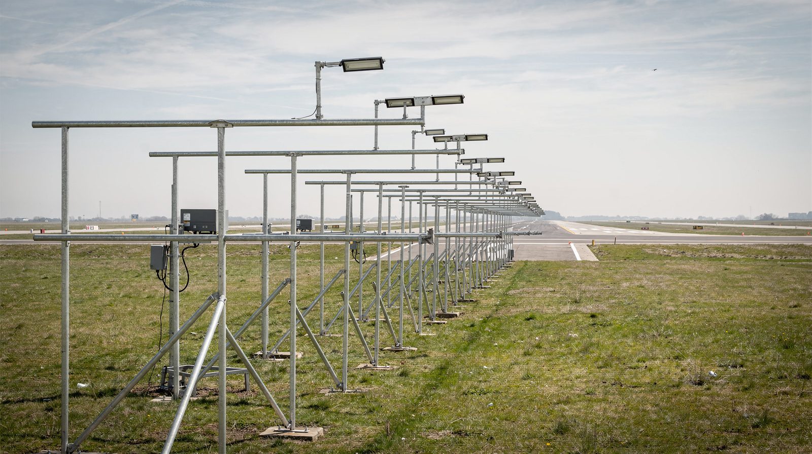
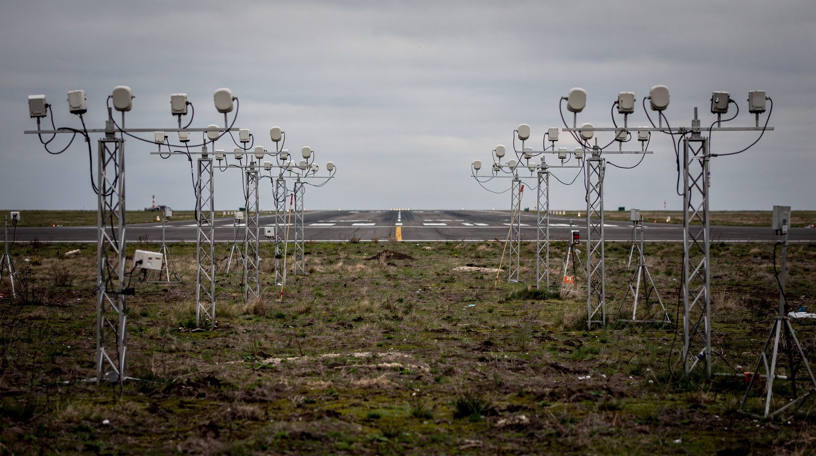
Inter-unit spacing is the precisely defined distance between adjacent light fixtures in airport lighting systems. These systems include runway edge lights, centerline lights, touchdown zone lights, taxiway and approach lighting, and more. The specific intervals are determined by regulatory authorities such as the FAA and ICAO and are tailored for each lighting type and operational need.
This spacing is not arbitrary. It results from decades of research in pilot visual perception, technical limitations, and operational safety. The correct application of inter-unit spacing ensures that pilots see clear, continuous light patterns for orientation, distance judgment, and alignment, especially in darkness or low-visibility conditions.
Failure to observe proper inter-unit spacing can compromise safety, cause visual confusion, or even result in regulatory penalties for airports.
Why Is Inter-Unit Spacing Important?
Inter-unit spacing plays a pivotal role in airfield safety, efficiency, and regulatory compliance:
- Pilot Visual Guidance: Pilots depend on the consistency and continuity of lighting patterns for landing, takeoff, and taxiing. Uniform spacing helps them quickly interpret the airfield layout, judge distances, and maintain alignment.
- Operational Safety: Gaps in lighting (due to excessive spacing) or glare (from lights too close together) can cause spatial disorientation, increase cognitive workload, or lead to dangerous errors such as runway incursions.
- Standardization: Consistent spacing across airports allows pilots to anticipate visual cues regardless of location, reducing training time and minimizing confusion in emergencies.
- Regulatory Compliance: FAA and ICAO require strict adherence to inter-unit spacing standards. Non-compliance can lead to decertification or operational restrictions.
- Maintenance Efficiency: Regular spacing simplifies inspections and troubleshooting. Technicians can quickly locate outages or misalignments by measuring distances between fixtures.
Regulatory Standards and Guidance
Both FAA and ICAO provide detailed standards for inter-unit spacing in key documents:
- FAA AC 150/5340-30J: Covers design and installation details for all airport visual aids, specifying maximum spacings and exceptions for each lighting type.
- ICAO Annex 14, Volume I: Sets global minimum and maximum spacing for each system, ensuring consistency for international flights.
- FAA AIM (Aeronautical Information Manual), Chapter 2: Offers operational guidelines for interpreting airfield lights.
Regulatory compliance is mandatory. During construction, upgrades, or certification reviews, authorities carefully check that all spacings meet the published requirements. Deviations must be immediately corrected or reported via NOTAM, and can result in operational restrictions until resolved.
Standard Inter-Unit Spacing by Lighting Type
Runway Edge Lights
- Spacing: 200 ft (61 m) maximum. Increases up to 400 ft (122 m) permitted at intersections.
- Color: White (last 2,000 ft or half the runway in yellow for caution).
- Purpose: Defines runway width for takeoff/landing.
Runway Centerline Lights
- Spacing: 50 ft (15 m) intervals.
- Color: White, alternating red/white for the last 3,000 ft, all red in the last 1,000 ft.
- Purpose: Precise alignment, especially in low-visibility CAT II/III operations.
Touchdown Zone Lights (TDZLs)
- Spacing: 100 ft (30 m) intervals, in pairs of 3-light bars on both sides of centerline.
- Color: White.
- Purpose: Indicates optimal touchdown area for pilots.
Threshold Lights
- Spacing: 3–4 m (10–13 ft) apart across the runway width.
- Color: Green (approach), red (departure).
- Purpose: Marks start (landing) and end (takeoff) of the runway.
Runway End Identifier Lights (REILs)
- Spacing: 40–60 ft (12–18 m) apart, flanking the threshold.
- Color: Flashing white.
- Purpose: Rapidly identifies runway end in poor visibility.
Approach Lighting Systems (ALS)
- Spacing: 100 ft (30 m) between main approach lights, extends up to 3,000 ft (914 m) from threshold.
- Color: White, sometimes red.
- Purpose: Guides pilots from instrument to visual approach.
Taxiway Edge Lights
- Spacing: 200 ft (61 m) maximum, reduced to 50 ft (15 m) on curves/intersections.
- Color: Blue.
- Purpose: Marks taxiway boundaries for ground movement.
Taxiway Centerline Lights
- Spacing: 50 ft (15 m), down to 25 ft (7.5 m) on tight curves.
- Color: Green (sometimes alternating green/yellow at runway interfaces).
- Purpose: Indicates taxiway center for safe taxiing.
Quick Reference Table: Inter-Unit Spacing
| Lighting System | Standard Spacing | Color(s) | Exceptions/Notes |
|---|---|---|---|
| Runway Edge Lights | 200 ft (61 m) max | White/Yellow | 400 ft (122 m) at intersections |
| Runway Centerline Lights | 50 ft (15 m) | White/Red | None |
| Touchdown Zone Lights (TDZL) | 100 ft (30 m) | White | Pairs, both sides of centerline |
| Threshold Lights | 10–13 ft (3–4 m) | Green/Red | Spans runway width |
| REILs | 40–60 ft (12–18 m) | White (flashing) | Spacing by runway width |
| Approach Lighting (ALS) | 100 ft (30 m) | White/Red | 1,400–3,000 ft (420–900 m) from threshold |
| Taxiway Edge Lights | 200 ft (61 m) max | Blue | 50 ft (15 m) on curves/intersections |
| Taxiway Centerline Lights | 50 ft (15 m) | Green/Yellow | 25 ft (7.5 m) on tight curves or intersections |
How Is Inter-Unit Spacing Used in Practice?
- Runway Operations: Edge and centerline lights at standard intervals form continuous guidance lines for pilots, aiding in alignment and distance judgment during takeoff and landing, even in fog, rain, or at night.
- Landing Roll: Color and spacing changes (e.g., edge lights from white to yellow, centerline from white to red) indicate remaining runway, supporting safe deceleration or go-around decisions.
- Taxi Operations: Taxiway edge and centerline lights, spaced uniformly, with closer intervals on curves, guide pilots safely between runways, ramps, and parking.
- Instrument Approaches: Approach lighting systems with precise spacing create a clear, reliable visual path from the instrument environment to the runway.
- Low-Visibility Operations: In CAT II/III conditions, strict adherence to spacing is mandated, any deviation can force downgrades in airport operational status.
- Maintenance: Uniform spacing enables rapid identification of outages, technicians can easily spot missing or malfunctioning fixtures by checking intervals.
Examples and Use Cases
- Night Landings: A pilot sees runway edge lights transition from white to yellow, instantly recognizing entry into the runway’s caution zone (last 2,000 ft).
- Foggy Takeoffs: Centerline lights every 50 ft allow precise alignment, minimizing risk of runway excursions in zero-visibility.
- Taxiway Turns: At complex intersections, edge lights at 50 ft intervals help pilots follow tight curves without veering off path.
- Instrument Approaches: ALS lights at 100 ft intervals create a recognizable approach path, even in heavy weather.
Special Considerations and Exceptions
- Intersections: Edge light spacing may increase to 400 ft to accommodate geometry, but must revert to standard immediately after.
- Displaced Thresholds: Lighting is repositioned to clearly mark landing zones.
- CAT II/III Operations: No spacing deviations permitted, any changes must be reported and may restrict operations.
- Construction: Temporary lighting with alternate spacings only allowed with regulatory approval and NOTAM notification.
- New Technologies: LED and adaptive systems must still adhere to regulatory spacing minimums and maximums.
Visual and Color Coding Cues
- White: Runway edge and centerline, ALS.
- Yellow: Runway edge caution zone.
- Red: Runway end, final approach warning.
- Green: Threshold, taxiway centerline.
- Blue: Taxiway edge.
- Alternating Green/Yellow: Runway/taxiway interfaces.
Mnemonic:
“White for runway, blue for taxi, green to go, yellow for caution, red for stop.”
How to Find Inter-Unit Spacing Info Before Flight
- Chart Supplement (A/FD): Lists lighting types and locations.
- Instrument Approach Charts: Show ALS and TDZL layouts.
- NOTAMs: Report temporary changes or outages.
- Airport Diagrams: Illustrate lighting placement and sometimes spacings.
- Regulatory Documents: FAA ACs, AIM, ICAO Annex 14 for standards.
Pilots are encouraged to review these sources in preflight planning, especially for night or instrument operations.
Key Terms and Definitions
- Runway Edge Light: White (or partially yellow) lights installed along runway edges.
- Runway Centerline Light: In-pavement lights marking the longitudinal center of the runway.
- Taxiway Edge Light: Blue lights outlining taxiways.
- Taxiway Centerline Light: Green (or green/yellow) in-pavement lights guiding taxi route.
- Touchdown Zone Light (TDZL): White light bars marking the landing touchdown area.
- Threshold Light: Green/red lights indicating runway start/end.
- REIL: Flashing lights marking runway ends.
- ALS: Approach lighting system, forming visual approach path.
Conclusion
Inter-unit spacing is a fundamental aspect of airport lighting, directly impacting pilot situational awareness, operational safety, and regulatory compliance. By following the precise standards set by the FAA and ICAO, airports ensure their lighting systems provide clear, continuous, and effective visual guidance, underpinning safe airfield operations in all conditions.
For airports, pilots, and engineers alike, understanding and maintaining correct inter-unit spacing is essential for modern aviation safety and efficiency.
Frequently Asked Questions
- What is inter-unit spacing in airport lighting?
- Inter-unit spacing is the regulated distance between adjacent lights in airport lighting systems, such as runway edge, centerline, and taxiway lights. This uniform spacing ensures pilots receive clear, continuous visual cues for safe navigation, especially in low visibility.
- Why is inter-unit spacing important for pilots?
- Proper inter-unit spacing creates consistent light patterns, helping pilots judge distances and maintain alignment during takeoff, landing, and taxiing. Incorrect spacing can cause dark gaps or glare, increasing safety risks and regulatory non-compliance.
- What are the standard inter-unit spacings for common airport lights?
- Typical spacings are: Runway edge lights – 200 ft (61 m) max, runway centerline lights – 50 ft (15 m), touchdown zone lights – 100 ft (30 m), taxiway edge lights – 200 ft (61 m) max, taxiway centerline lights – 50 ft (15 m). Exceptions apply for intersections or curves.
- Who sets the standards for inter-unit spacing?
- The FAA (in the U.S.) and ICAO (internationally) set detailed standards for inter-unit spacing in documents like FAA AC 150/5340-30J and ICAO Annex 14. Airports must comply to maintain certification and operational status.
- How is inter-unit spacing maintained and checked?
- Lighting layouts are carefully measured during installation and regularly inspected for compliance. Maintenance teams use spacing as a reference to quickly identify outages or misalignments, ensuring continued safety and regulatory adherence.
This is a reference entry. TarmacView provides drone inspection services and doesn't sell the equipment or materials described in this glossary.