Blast Erosion
Blast erosion is the deterioration of airport infrastructure caused by the high-speed, high-temperature jet exhaust from aircraft engines. It affects surfaces l...
5 min read
Airport safety
Runway maintenance
+2
Jet blast is the high-velocity exhaust gases from jet engines during takeoff and ground operations, capable of eroding pavement surfaces, displacing FOD, damaging structures, and injuring personnel. Covers jet blast velocity and temperature, effects on pavement (erosion, polished aggregate, thermal stress), blast pad design, and inspection for jet blast damage.

Jet blast is the high-velocity, high-temperature stream of exhaust gases expelled from the rear of jet engines—including turbojet, turbofan, and turboprop engines—during aircraft ground operations. Unlike the exhaust of an airborne engine, which rapidly dissipates in the free atmosphere, jet blast on the ground interacts directly with pavement surfaces, ground support equipment, adjacent structures, and personnel. The damaging potential of jet blast is a function of three interrelated parameters: exhaust velocity, exhaust temperature, and blast spread pattern. The ICAO Aerodrome Design Manual (Doc 9157, Part 2) formally defines jet blast as the high-velocity exhaust stream generated by aeroplane engines that can cause erosion of surfaces, damage to other aircraft, and injury to personnel, requiring specific design provisions to mitigate its effects at aerodromes.
At the engine nozzle exit, exhaust gas velocity varies significantly by engine type and thrust setting. Modern high-bypass turbofan engines—such as the General Electric GE90 (used on Boeing 777), Rolls-Royce Trent 800, and Pratt & Whitney PW4000—produce exhaust velocities between 250 and 350 mph (110–156 m/s) at takeoff thrust. Some large military engines and older low-bypass turbojets can produce exit velocities exceeding 500 mph (220 m/s). The Boeing 737-800 with CFM56-7B engines generates jet exhaust velocities of approximately 245 mph (110 m/s) at full takeoff thrust. The Boeing 777-300ER with GE90-115B engines—the most powerful commercial turbofan in service with 115,000 lbf (512 kN) thrust—produces exhaust velocities approaching 300 mph (134 m/s) with a total exhaust mass flow exceeding 3,600 lb/s (1,633 kg/s). The Airbus A380 with Engine Alliance GP7200 engines (76,000 lbf or 338 kN each) produces comparable exhaust velocities across four engines, creating a cumulative blast zone up to 200 feet (61 m) wide.
Velocity decay downstream of the nozzle follows an inverse relationship with distance. According to the jet decay model documented by the Transportation Research Board (TRB) and in FAA research studies, the centerline velocity decreases proportionally to the inverse of the distance from the nozzle. This relationship is mathematically expressed as Vx/V0 = 1/(1 + kx/D), where Vx is the centerline velocity at distance x from the nozzle, V0 is the exit velocity, D is the nozzle diameter, and k is an empirical decay constant ranging from 5 to 7 for turbofan engines. At a distance of 100 feet (30 m) behind the engine, the velocity typically drops to 30–40% of the exit velocity. At 500 feet (152 m), it is approximately 10% of the exit velocity—which for a large turbofan still translates to 30–35 mph (13–16 m/s), sufficient to overturn ground support equipment and destabilize pedestrians. For widebody aircraft at takeoff thrust, hazardous velocity zones can extend more than 2,000 feet (600 m) behind the aircraft. The FAA research report DOT/FAA/TC-22/21 documented that the jet blast from a Boeing 777-300ER at takeoff thrust produces measurable velocities above 35 mph at distances exceeding 1,800 feet (550 m) behind the aircraft.
Exhaust gas temperature (EGT) at the nozzle exit ranges from 400°C to 650°C (750°F–1,200°F) depending on engine type, power setting, and ambient conditions. At takeoff thrust, EGT typically ranges between 500°C and 650°C (932°F–1,202°F). At idle thrust, temperatures drop to 150°C–300°C (302°F–572°F). The temperature of the exhaust stream decays with distance more rapidly than velocity, following a logarithmic decay profile rather than the inverse decay of velocity. This is because temperature dissipation is governed by turbulent mixing with ambient air and radiative heat transfer to the surroundings, in addition to the momentum-driven dilution of the jet. At 50 feet (15 m) behind the engine, exhaust temperature is approximately 50–60% of the exit temperature. At 200 feet (61 m), it drops to 20–30%. At 400 feet (122 m), the temperature elevation above ambient may be as low as 5–10°C (9–18°F).
However, even at reduced temperatures, the thermal load imposed on pavement surfaces is significant for several reasons. Asphalt binder (bitumen) begins to soften at 50°C (122°F) and flows noticeably above 100°C (212°F). The ring-and-ball softening point test (ASTM D36) for typical PG 64-22 binder shows softening at 46–52°C (115–126°F). When pavement surface temperatures exceed this threshold repeatedly, the binder migrates to the surface (bleeding) or is flushed away by the mechanical action of the exhaust stream. The repeated exposure of pavement surfaces to temperatures exceeding 300°C (572°F)—even for short durations of 10–30 seconds per event—causes irreversible thermal degradation of the bituminous binder. This degradation manifests as carbonization (pyrolysis of the hydrocarbon molecules), embrittlement (loss of the binder’s elastic properties), and loss of adhesion between the binder and aggregate particles.
The thermal impact on concrete pavements is equally significant but manifests differently. The coefficient of thermal expansion for Portland cement concrete is approximately 10–14 microstrain per °C (5.5–7.8 microstrain per °F). When the surface layer of a concrete slab is heated from 20°C (ambient) to 300°C (572°F) in seconds, the restrained thermal expansion generates compressive stresses of 2,500–5,000 psi (17–35 MPa)—sufficient to exceed the tensile strength of typical concrete (400–600 psi or 2.8–4.1 MPa), causing surface spalling before the compressive strength is reached.
Jet blast does not emerge as a narrow coherent jet but rather as a spreading conical or fan-shaped plume governed by the principles of turbulent free-jet flow. The spread angle is influenced by engine design—high-bypass turbofans produce broader, more diffuse plumes compared to low-bypass turbofans and turbojets. The spread half-angle (the angle from the centerline to the edge of measurable velocity) ranges from 10 to 15 degrees for modern turbofans. For the CFM56-7B on the Boeing 737, the half-angle is approximately 12 degrees; for the GE90 on the Boeing 777, it is approximately 14 degrees due to the larger fan diameter and higher bypass ratio.
Ground interaction effects significantly alter the free-jet behavior. As the exhaust plume propagates downstream, it attaches to the ground surface through the Coanda effect—the tendency of a fluid jet to follow a convex surface. This ground attachment causes the plume to flatten and spread laterally, increasing the width of the affected zone by a factor of 2–3 compared to the theoretical free-jet width at the same downstream distance. This ground-effect spreading subjects a width of 100–200 feet (30–60 m) of pavement area behind a large aircraft to significant erosive forces. The lateral extent is influenced by the engine height above ground. Engines mounted higher (as on the Boeing 747-8 or Airbus A380 with engines above 16 feet or 5 m ground clearance) produce less ground interaction than low-mounted engines (Boeing 737 or Airbus A320 at 3–4 feet or 1–1.2 m clearance).
Experimental research published in Promet - Traffic & Transportation (Wang et al., 2015) measured the dynamic pressure field of jet exhaust from a turbofan engine and found that the pressure at the center of the jet flow decreases rapidly with a maximum decay rate of 41.7% over the first 10 meters from the nozzle. The dynamic pressure 150 m (492 ft) from the nozzle was measured at 58.8 Pa, corresponding to a wind velocity of 10 m/s (22 mph). The temperature-affected range (elevation of 40°C above ambient) extended 113.5 m in length and 20 m in width, defining the envelope within which pavement thermal damage can be expected.
Boeing and Airbus provide jet blast velocity and temperature contour charts in their Airport Planning Manuals. These charts delineate zones where exhaust velocity exceeds thresholds of 35 mph (56 km/h) and 50 mph (80 km/h) —the critical velocities at which personnel and equipment are at risk according to the International Air Transport Association (IATA) Airport Handling Manual. The 35 mph contour defines the boundary beyond which ground crew can safely operate without risk of being knocked over, while the 50 mph contour defines the limit for ground support equipment stability. These charts are essential inputs to apron layout design, gate assignment planning, blast protection infrastructure sizing, and the development of airport-specific ground safety procedures.
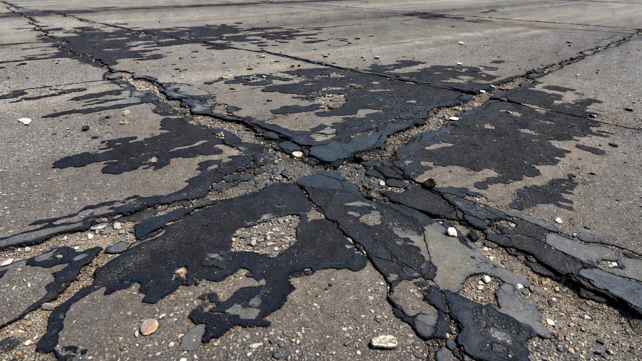
Asphalt (flexible) pavement is particularly vulnerable to jet blast damage due to the temperature sensitivity of its bituminous binder. The FAA Advisory Circular AC 150/5380-6B defines jet blast erosion on asphalt pavements as a darkened area where the bituminous binder has been burned or carbonized by engine exhaust. This distress category is distinct from traffic-related wear and must be identified separately during Pavement Condition Index (PCI) surveys conducted per ASTM D5340. The effects on asphalt pavement can be categorized into three primary mechanisms: surface erosion and binder degradation, polished aggregate, and wheel track rutting from thermal softening.
When jet exhaust impinges on an asphalt surface, two concurrent damage mechanisms are activated simultaneously. The mechanical component involves the high-velocity gas stream scouring the surface like a sandblaster, removing fine aggregate particles and eroding the asphalt binder matrix. The thermal component involves heating the binder to temperatures that cause it to soften, flow, oxidize, and eventually carbonize. The combined effect is a progressive removal of surface material, starting with the loss of the thin binder film that coats aggregate particles (surface raveling), followed by loss of fine aggregate, and eventually exposure and dislodgement of coarse aggregate.
The FAA and ASTM D5340 standard describe jet-blast erosion on asphalt as darkened areas varying in depth up to approximately 1/2 inch (13 mm) . The darkened appearance is caused by the thermal carbonization of the bitumen—the binder is heated to the point where it undergoes pyrolysis, turning black and losing its adhesive and cohesive properties. In advanced cases, the binder may be completely burned away, leaving exposed aggregate that is easily dislodged by subsequent blast events, aircraft tire action, or FOD removal equipment. The rate of erosion is influenced by the asphalt mix design, with surface course mixes using smaller nominal maximum aggregate size (NMAS) being more susceptible than coarser mixes. Open-graded friction course (OGFC) and porous asphalt surfaces are particularly vulnerable due to their higher air void content (18–22%), which provides pathways for hot gases to penetrate deeper into the pavement structure.
No severity levels are defined for jet-blast erosion in the ASTM D5340 standard. It is sufficient to indicate that jet-blast erosion exists. This is because jet blast damage tends to be binary in nature—either the binder has been thermally degraded or it has not. The extent of the damaged area (measured in square feet or square meters) is the primary metric for quantifying the distress. The ICAO Aerodrome Design Manual (Doc 9157, Part 3) recommends that pavements in jet blast-affected areas use dense-graded hot mix asphalt with maximum air voids of 3–5% to minimize the penetration of hot exhaust gases into the pavement structure.
Extended exposure of aggregate particles to high-velocity jet exhaust containing entrained particulates can polish the exposed surface of the aggregate. This polishing effect reduces the microtexture of the aggregate, diminishing the pavement’s skid resistance. The FAA pavement maintenance advisory circular (AC 150/5380-6B) addresses polished aggregate as a separate distress category. Polished aggregate is particularly hazardous on runway ends and taxiway pavements where aircraft braking and directional control are critical. The polishing mechanism is abrasive rather than thermal—the high-velocity gas carries sand, dust, and small debris particles that impact the aggregate surface at velocities of 100–300 mph (45–134 m/s), gradually wearing down microscopic asperities.
Aggregate polishing resistance is measured by the polished stone value (PSV) test per ASTM D3319 or AASHTO T279. Aggregates with PSV below 40 are considered susceptible to polishing and should not be used in jet blast-affected pavement surfaces. Hard, angular aggregates such as granite, basalt, and traprock with PSV exceeding 45 are preferred for surface courses in jet blast zones. The FAA specifies that pavement surfaces in critical areas (runway ends, taxiway intersections, and jet blast zones) must achieve a minimum friction coefficient measured by continuous friction measurement equipment (CFME) of 0.50 for runways and 0.45 for taxiways at 40 mph (65 km/h) test speed.
Repeated exposure of asphalt pavement to jet exhaust temperatures above the binder softening point causes the pavement surface to deform under aircraft wheel loads, a mechanism that differs fundamentally from load-associated rutting. Load-associated rutting results from shear deformation in the binder and aggregate structure under heavy channelized traffic, typically occurring over years of service. Thermal softening rutting is localized to areas where jet exhaust impinges on the pavement while aircraft are stationary or moving slowly at high thrust—such as at runway holding positions, engine run-up pads, and gate pushback positions—and can occur after only a few events.
The resulting ruts collect water, increasing the risk of hydroplaning. They also create uneven surfaces that accelerate other distress mechanisms such as fatigue cracking and spalling. The FAA P-404 fuel-resistant hot mix asphalt specification was developed specifically to address this issue by using a highly polymer-modified binder with a Performance Grade of PG 82-22 or higher, providing significantly greater resistance to thermal deformation than conventional P-401 hot mix asphalt (which typically uses PG 64-22 or PG 70-28 binder). The polymer-modified binder maintains its viscosity at temperatures up to 80°C (176°F), compared to 64°C (147°F) for standard binder, providing a substantial margin against thermal softening from jet blast exposure.
Portland cement concrete (PCC) pavement, while more resistant to thermal degradation than asphalt, is not immune to jet blast damage. The mechanisms of damage are fundamentally different, driven by thermal stress rather than binder degradation. Understanding these mechanisms is critical for airport pavement engineers conducting condition surveys on concrete runways, taxiways, and aprons.
When jet exhaust at temperatures of 400–650°C (750–1,200°F) impinges on a concrete surface, the rapid heating creates a steep thermal gradient through the depth of the slab. The surface layer attempts to expand, but is restrained by the cooler underlying concrete. This restraint generates compressive thermal stresses at the surface that can exceed the tensile strength of the concrete, resulting in spalling—the detachment of thin layers or flakes from the surface. The stress magnitude follows Hooke’s law: σ = E·α·ΔT, where σ is thermal stress, E is the elastic modulus of concrete (4–6 million psi or 28–42 GPa), α is the coefficient of thermal expansion (10–14 × 10⁻⁶/°C), and ΔT is the temperature differential through the slab depth.
For a ΔT of 280°C (500°F) through the top inch of concrete, the theoretical compressive stress at the surface is approximately 3,500 psi (24 MPa)—far exceeding the 400–600 psi (2.8–4.1 MPa) tensile strength. The concrete fails not in compression (where its strength is 4,000–6,000 psi or 28–42 MPa) but in tension as the expanding surface layer bends upward relative to the cooler substrate, creating tensile stresses at the bond line between the heated and unheated zones.
Concrete spalling from jet blast is characterized by the detachment of surface mortar, exposing coarse aggregate. In severe cases, the spalling depth can reach 0.5–1.0 inch (13–25 mm) and may expose reinforcing steel in thin slabs. The spalled areas are typically irregular in shape and located in the zone directly behind the aircraft engine exhaust outlets. On jointed concrete pavements, spalling is most common near joints and cracks, where the discontinuity in the slab provides a preferential path for heat penetration and stress concentration.
The mechanism is exacerbated by the presence of moisture in the concrete pores. When heated rapidly, pore water vaporizes and expands, generating internal pressures that can cause explosive spalling. This is the same mechanism observed in concrete exposed to fire. Concrete with high moisture content and low permeability is most susceptible to explosive spalling. The critical water saturation level is approximately 80% of saturation—above this threshold, the vapor pressure generated during rapid heating can exceed the tensile strength of the concrete, causing violent ejection of surface fragments.
Repeated thermal cycling from jet blast—heating during engine operation followed by cooling during idle periods—induces fatigue in the concrete surface layer. This fatigue causes delamination along horizontal planes parallel to the surface, typically at depths of 1/8 to 1/4 inch (3–6 mm). Delamination occurs when the tensile stresses from repeated thermal expansion and contraction exceed the bond strength between the cement paste layers. Delaminated areas produce a hollow sound when tapped with a hammer during inspection and eventually break loose as shallow spalls. The extent of delamination can be mapped using chain drag surveys or infrared thermography, both of which detect the air gap beneath the delaminated layer.
Aggregate popouts occur when aggregate particles near the surface expand at a different rate than the surrounding cement paste under thermal loading. Differences in the coefficient of thermal expansion (CTE) between the aggregate and the paste generate localized stresses that cause the aggregate particle to detach, leaving a conical cavity in the surface. Popouts are typically 1/4 to 1 inch (6–25 mm) in diameter and, while individually small, can accumulate to create a rough, irregular surface that traps debris and reduces skid resistance. The use of aggregate with a CTE closely matched to the cement paste (within 2 microstrain per °C) significantly reduces popout risk. Aggregates with high quartz content (such as chert and quartzite) have high CTE values (11–14 × 10⁻⁶/°C) and should be avoided in concrete pavements exposed to jet blast.
Scaling is the loss of surface mortar over a broader area, exposing coarse aggregate but without the localized detachment characteristic of spalling. Scaling from jet blast presents as a roughened surface with exposed aggregate particles standing in relief above the surrounding mortar. The 1/4 to 1/2 inch (6–13 mm) of the surface layer is gradually worn away by the combined action of thermal stress and mechanical abrasion from entrained particulates. Unlike spalling, which involves discrete fragments breaking away, scaling is a progressive wearing process that reduces the surface mortar thickness uniformly across the affected area.
The U.S. Army Corps of Engineers Unified Facilities Manual (UFM 3-270-01) specifically identifies concrete pavement damage from jet blast as including spalling, delamination, aggregate popouts, scaling, and cracking. The manual recommends that PCC mixes in jet blast-prone areas incorporate air-entrainment (6–8% air content by volume), low water-cement ratios (0.40 or lower), and high cementitious content (minimum 600 lb/yd³ or 356 kg/m³) to improve thermal shock resistance. Air-entrainment provides microscopic voids that accommodate the expansion of pore water during rapid heating, reducing the risk of explosive spalling. Supplementary cementitious materials such as fly ash (15–25% replacement), ground granulated blast furnace slag (30–50%), and silica fume (5–8%) densify the cement paste matrix, reducing permeability and improving thermal durability.
One of the most significant safety hazards associated with jet blast is its ability to generate and displace foreign object debris (FOD) . The FAA Advisory Circular 150/5210-24A on Airport FOD Management explicitly identifies jet blast as a primary mechanism for FOD movement across the airfield. When jet exhaust dislodges pavement material—either eroded aggregate from a damaged surface or loose material from unsealed joints and cracks—these particles become projectiles propelled at velocities sufficient to cause damage to aircraft, vehicles, and personnel.
Jet blast creates FOD through three distinct mechanisms. Primary generation occurs when the exhaust stream directly dislodges pavement material—aggregate particles from eroded asphalt, mortar fragments from spalled concrete, or loose stones from unsealed joints and cracks. Secondary displacement occurs when the blast stream picks up existing debris from pavements, shoulders, or infield areas and transports it to operational surfaces. Tertiary propagation occurs when debris propelled by one aircraft’s blast becomes a hazard to subsequent aircraft, ground vehicles, or personnel—a chain reaction that can propagate across large areas of the airfield.
The FAA AC 150/5210-24A notes that outboard engines of aircraft transitioning from a relatively large-width runway onto a smaller-width taxiway can blow loose dirt and materials from the shoulder and infield areas onto the runway surface. For four-engine aircraft such as the Boeing 747-8 and Airbus A380, the outboard engines can move debris from the runway edge and shoulder areas—where FOD tends to accumulate—back toward the center of the runway or taxiway. This mechanism is particularly dangerous during runway changes or when aircraft execute 180-degree turns on runways (backtrack operations), directing full-thrust blast toward runway edges that may contain loose gravel, soil, or vegetation debris.
The hazards posed by jet blast-propelled FOD include engine ingestion, tire damage, personnel injury, and aircraft structural damage. The FAA estimates that engine FOD costs the global aviation industry $4–5 billion annually in direct repair costs and lost revenue. Each engine ingestion event typically results in $1–10 million in repair costs depending on the severity of fan blade damage, with compressor blade replacement requiring full engine teardown and overhaul. Tire damage from FOD is estimated to account for 15–20% of all aircraft tire failures, with each event costing $5,000–50,000 including replacement, inspection of wheel assemblies, and potential collateral damage to brake systems and wheel well structures.
Personnel injuries from FOD propelled by jet blast range from minor lacerations to fatalities. The FAA AC 150/5210-24A states: “Personnel injuries or even death can occur when jet blast propels FOD through the airport environment at high velocities.” Documented incidents include ground crew struck by dislodged pavement fragments, baggage cart operators hit by debris thrown up by jet blast, and maintenance personnel injured by loose hardware picked up by engine exhaust. Aircraft structural damage includes dented skin panels, cracked windshields, damaged control surfaces, and punctured fuel tanks.
The most effective FOD prevention strategy in the context of jet blast is maintaining pavements in good condition—free of cracks, spalls, and loose aggregate. The FAA pavement maintenance advisory circular (AC 150/5380-6B) recommends immediate repair of surface defects in jet blast zones to prevent FOD generation. This includes crack sealing using hot-applied bituminous sealant per ASTM D6690, partial-depth spall repair using polymer-modified patching materials, and surface patching using fuel-resistant materials such as P-404 hot mix asphalt.
Regular sweeping of jet blast-affected areas using mechanical sweepers with vacuum assist is essential to remove loose debris before it becomes a projectile hazard. The FAA recommends that runway and taxiway FOD inspection frequencies—as specified in the airport’s FOD management program per AC 150/5210-24A—be increased in areas with documented jet blast erosion. Many airports now employ FOD detection systems using radar or optical sensors mounted on sweepers or dedicated inspection vehicles to identify debris down to 1/4 inch (6 mm) diameter on operational surfaces. The ICAO Doc 9137 (Airport Services Manual, Part 8) provides additional guidance on FOD prevention programs, emphasizing the role of pavement condition in FOD generation and the need for regular inspections of jet blast-prone areas.
A blast pad is a purpose-built, non-load-bearing surface located at the ends of runways, engineered to absorb and resist the erosive forces of jet engine exhaust and propeller wash. The blast pad is not designed to support aircraft loads—it is a sacrificial protective surface between the operational runway and the surrounding graded area. According to both ICAO Annex 14, Volume I and the FAA Advisory Circular 150/5300-13B, the blast pad is a mandatory safety feature for federally funded airports serving jet aircraft.
The FAA AC 150/5300-13B specifies that blast pad length and width are determined by the critical design aircraft for each runway, accounting for the Airport Reference Code (ARC). The blast pad must extend across the full width of the runway pavement plus the runway shoulders. For airports serving Code E and F aircraft (wingspan 171–262 feet or 52–80 m), blast pad lengths of 200–300 feet (60–90 m) are typical. For Code C aircraft (Boeing 737, Airbus A320), blast pad lengths of 100–150 feet (30–46 m) are common.
ICAO Annex 14, Volume I, requires a minimum prepared area of 30 meters (98 feet) beyond the runway end. Chevron markings are required if the paved area before a threshold exceeds 60 meters (197 feet) and is not intended for aircraft use. The ICAO Aerodrome Design Manual (Doc 9157, Part 3—Pavements) provides additional guidance on blast pad surface selection and construction, including specific recommendations for cohesive and non-cohesive soil types. For soils susceptible to erosion by jet blast—particularly non-cohesive sands and silts—the manual recommends paving the blast pad surface or providing alternative soil stabilization measures.
| Standard | Minimum Length | Marking Requirement | Load-Bearing Requirement |
|---|---|---|---|
| FAA AC 150/5300-13B | Per runway/ARC | Yellow chevrons per AC 150/5340-1M | Not designed for aircraft loads |
| ICAO Annex 14 | 30 m (98 ft) | Chevrons if paved area >60 m | Not designed for aircraft loads |
| ICAO Aerodrome Design Manual | As required by critical aircraft | Per Annex 14 standards | Erosion-resistant surface only |
Blast pads may be constructed from asphalt concrete (P-401 or P-403), Portland cement concrete (P-501), or stabilized soil/aggregate, depending on the operational requirements. For major airports serving jet aircraft, the FAA recommends paved blast pads—either asphalt or concrete—to withstand the mechanical and thermal loads of high-thrust jet exhaust. For smaller general aviation airports operating only propeller-driven aircraft and light jets, compacted aggregate or stabilized turf may be acceptable, provided the surface is maintained free of erosion and FOD.
The surface must be sloped to provide positive drainage away from the runway edge and off the blast pad pavement. Standing water on blast pads accelerates pavement deterioration and creates a safety hazard if blown onto the runway by blast or aircraft wake. Longitudinal and transverse drainage gradients of 1.5–2.0% are typical, consistent with FAA design standards. The subgrade beneath the blast pad must be compacted to 95% of maximum dry density per ASTM D698 (Standard Proctor) or equivalent to prevent differential settlement and erosion of the supporting layer.
Blast pads are marked with yellow chevrons per FAA AC 150/5340-1M and ICAO Annex 14, Chapter 7. Chevrons are elongated V-shaped stripes oriented with the points toward the runway threshold, extending across the full width of the blast pad. The chevrons are typically 20–30 feet (6–9 m) in length from point to trailing edge and spaced at 15–25 feet (4.5–7.6 m) on center, depending on the blast pad dimensions. No runway designation markings, threshold bars, or touchdown zone markings are present on blast pads. The chevrons provide an unambiguous visual distinction between the operational runway pavement and the non-load-bearing blast pad, preventing pilots from inadvertently using the blast pad for takeoff or landing.
Blast pads are distinct from stopways and runway end safety areas (RESA) . A stopway is a load-bearing surface capable of supporting aircraft in a rejected takeoff and is included in the accelerate-stop distance available (ASDA). A RESA is a graded, cleared area beyond the runway end designed to accommodate overrun aircraft and must extend 90 m (295 ft) from the runway end for Code 3 and 4 runways, or 240 m (787 ft) where practicable per ICAO standards. Blast pads serve none of these functions—they are erosion control features only and are never included in declared runway distances (TORA, TODA, ASDA, or LDA).
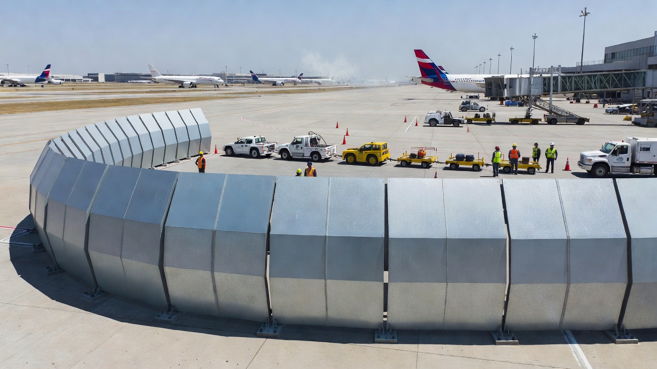
A blast fence—also called a jet blast deflector (JBD)—is a vertical or curved barrier structure designed to redirect high-velocity engine exhaust upward and away from adjacent areas. While blast pads control erosion of the horizontal surface, blast fences protect vertical space and adjacent lateral areas from the destructive effects of jet blast. Blast fences are critical infrastructure at airports where aircraft parking positions, taxiways, roadways, buildings, or public areas are located near jet engine exhaust zones.
Curved jet blast deflectors represent the industry standard design, perfected over 60+ years by manufacturers such as Blast Deflectors Inc. (BDI). The curved profile redirects exhaust gases upward at an angle of 90–110 degrees from horizontal, causing the plume to dissipate vertically rather than propagating laterally. The curvature follows a parabolic or circular arc with a radius typically equal to 80–120% of the fence height. The radius of curvature and height of the deflector are determined by the maximum thrust and exhaust velocity of the critical aircraft. Curved deflectors achieve deflection efficiencies of 70–85%, meaning that 70–85% of the exhaust momentum is redirected upward rather than passing over or through the barrier.
Vertical jet blast fences are simpler structures that rely on the momentum of the exhaust stream being blocked by a vertical wall. These are less aerodynamically efficient than curved deflectors (efficiency: 40–60%) but are simpler to construct and can be made from reinforced concrete, steel sheet, or precast panels. Vertical fences create more turbulence and back-pressure than curved designs, which can affect engine performance during run-up operations if placed too close to the aircraft.
Expanded metal (mesh) blast barriers allow a portion of the exhaust stream to pass through while breaking up the coherent jet into smaller, lower-energy eddies. These are suitable for lower-thrust applications such as taxiway holding positions and apron peripheral protection. Mesh barriers generate less back-pressure than solid barriers and are lighter, allowing for modular and relocatable installations. The open area ratio of expanded metal panels typically ranges from 40–60%, balancing deflection efficiency (50–65%) with pressure relief.
Light-duty deflectors are rated for taxi and breakaway thrust (typically 20–50% of maximum takeoff thrust) and are used near roadways, car parks, buildings, and other sensitive areas where aircraft operate at low power settings. Heavy-duty deflectors are rated for full-power engine run-ups and are typically used at runway ends and dedicated engine test cells, with structural capacity to withstand exhaust velocities exceeding 300 mph (134 m/s) and temperatures above 400°C (752°F).
The critical design parameters for blast fences are height, distance from aircraft, aerodynamic profile, and structural capacity.
Height: Blast fence height typically ranges from 12 to 25 feet (3.7–7.6 m) for commercial airport applications. The height required depends on the exhaust plume trajectory of the critical aircraft, which is a function of engine thrust, nozzle geometry, and ground clearance. Higher fences are required for larger aircraft with higher thrust. For Code F aircraft (Airbus A380, Boeing 747-8), blast fence heights of 20–25 feet (6–7.6 m) are typical. For Code C aircraft, 12–16 foot (3.7–4.9 m) fences are sufficient. The required height increases as the fence is placed closer to the aircraft, since the exhaust plume is more concentrated near the nozzle.
Distance from aircraft: A minimum clearance of 50 feet (15 m) from the aircraft tail to the front of the blast fence is recommended to ensure safe dissipation of exhaust momentum before contact with the barrier. This distance also accommodates ground support equipment movement, aircraft marshaling, and emergency access. The experimental study by Wang et al. (2015) demonstrated that the dynamic pressure behind a combined blast fence (at the protected side) can be reduced to less than 10 Pa—equivalent to a wind velocity of approximately 4 m/s (9 mph)—when the fence is properly positioned relative to the nozzle.
Aerodynamic profile: Curved deflectors with a radius-to-height ratio of approximately 1:1 provide optimal flow redirection with minimal back-pressure on the engine. Back-pressure reduction is important because excessive back-pressure can reduce engine thrust by 1–3%, increase fuel consumption, and cause engine surge in extreme cases. The study by Wang et al. found that combined blast fences (incorporating both solid and louvered elements) not only reduced the pressure of the flow in front of them but also solved the issues of excessive turbulence behind solid fences and excessive pressure behind louvered fences.
Structural capacity: Blast fences must withstand the combined mechanical loads of the exhaust jet impact (which can exceed 100 psf or 4.8 kPa at 10 feet distance), thermal loading from high-temperature exhaust (400°C+), and wind loads per applicable building codes (typically 90–120 mph or 145–193 km/h 3-second gust per ASCE 7). Hot-dip galvanized steel construction is standard for corrosion resistance in the airport environment, with the galvanized coating applied at 3–5 mils (75–125 microns) thickness per ASTM A123.
The primary structural material for blast fences is hot-dip galvanized steel. The galvanized coating provides corrosion protection against deicing chemicals (acetates, glycols, and urea-based compounds), jet fuel spillage (Jet A, Jet A-1), and atmospheric exposure. Panel options include solid roll-formed steel sheets (typically 10–14 gauge or 1.9–2.7 mm thickness) for maximum deflection efficiency, expanded metal mesh for partial deflection and reduced wind load (typically 3/4 inch or 19 mm opening size), and integrated acoustic panels for noise attenuation applications (achieving 15–25 dB reduction).
The structural framework may be carbon steel (ASTM A36 or A572), stainless steel (Type 304 or 316L) for corrosive environments, aluminum (6061-T6) for weight-sensitive installations, or fiberglass for electrical isolation requirements. Anchorage systems include mechanical expansion anchors (Hilti HVA or equivalent with 3,000–8,000 lb or 13–36 kN pullout capacity), chemical epoxy anchors for cracked concrete substrates, cast-in-place embedment plates for new construction (with 1–1.5 inch or 25–38 mm diameter anchor bolts), and frangible (break-away) bases for safety-critical locations where vehicle impact is a concern.
Aesthetic cladding can be applied to the landside face of blast fences located in public-view areas or near airport terminal buildings, integrating them visually with the airport architecture. Architectural finishes include powder coating (per AAMA 2604 or 2605), architectural precast concrete panels, and composite metal panel systems.
Blast deflectors must comply with FAA obstruction standards per 14 CFR Part 77—objects affecting navigable airspace. Blast fences within the obstacle limitation surfaces defined by ICAO Annex 14, Chapter 4 require obstruction marking and lighting per FAA AC 70/7460-1M (red or white obstruction lights, red-and-white paint pattern). FAA AC 150/5300-13B and ICAO Annex 14 provide guidance on the siting of blast fences relative to runways, taxiways, and aprons. Most commercial blast fence manufacturers provide compliance documentation and structural calculations stamped by a licensed professional engineer.
Inspection for jet blast damage is a specialized component of the airport pavement condition survey. Unlike traffic-induced distress, which is load-related and distributed along wheel paths, jet blast damage is localized to specific zones behind engine exhaust positions. Failure to differentiate blast damage from traffic distress can lead to incorrect pavement condition ratings and inappropriate repair strategies.
The ASTM D5340 Standard Test Method for Airport Pavement Condition Index Surveys includes jet blast erosion as a recognized distress type for asphalt (flexible) pavements. The survey procedure requires the inspector to identify sample units representative of the pavement condition, measure the area of each distress type within the sample unit, calculate the distress density as the area of distress as a percentage of sample unit area, apply the appropriate distress deduct value from the ASTM D5340 deduct value curves, and compute the Pavement Condition Index (PCI) on a scale of 0–100.
For jet blast erosion, the measured parameter is the area of affected pavement in square feet (or square meters). The ASTM standard specifies that jet blast erosion has no defined severity levels—it either exists or it does not. The deduct value is a function of the density of the damaged area. A PCI of 100 represents a perfect pavement condition; a PCI below 40 indicates poor condition requiring major rehabilitation. The standard specifies that when jet blast erosion is present, the inspector should note the extent of the area affected and whether the distress is active (continuing to progress) or inactive (stabilized).
On asphalt pavements, jet blast erosion appears as darkened, burned, or carbonized areas of the surface, typically located directly behind the engine exhaust position of aircraft parked, holding, or queuing for takeoff. The darkened area is accompanied by a loss of surface fines (raveling) and may exhibit binder bleeding in the transition zone between the burned area and unaffected pavement. The boundary between affected and unaffected pavement is typically sharp, conforming to the aerodynamic footprint of the exhaust plume. The inspector should measure the length and width of the affected area and note its orientation relative to the aircraft centerline.
On concrete pavements, jet blast damage appears as surface spalling, delamination (detectable by a hollow sound when tapped), aggregate popouts, and surface scaling. The affected area is irregular in shape and corresponds to the engine exhaust footprint. Concrete color may be altered in the affected zone due to thermal oxidation of the cement paste, typically appearing lighter (whitish or gray-tan) compared to unaffected concrete. The inspector should measure the depth of spalling using a straightedge and scale, and note whether reinforcing steel is exposed.
Jet blast damage must be distinguished from several other distress types. Load-associated fatigue cracking (alligator cracking) follows wheel paths and is characterized by interconnected cracks forming small polygons; jet blast erosion is a surface phenomenon without the crack pattern characteristic of structural fatigue. Weathering and raveling affects the entire surface uniformly over time due to environmental exposure, while jet blast erosion is distinctly localized to engine exhaust positions. Fuel spill damage from jet fuel spillage also dissolves asphalt binder, but the pattern is irregular and follows spill contours rather than the aerodynamic footprint of the exhaust plume. Thermal cracking (transverse cracking) produces regularly spaced cracks that extend through the full pavement depth, unlike the shallow surface carbonization of jet blast damage.
Routine visual inspection is the primary method for identifying jet blast damage. However, the following tools support detailed assessment. Thermal imaging cameras (forward-looking infrared or FLIR) can detect residual heat patterns in pavement that correlate with jet exhaust impingement zones, as the carbonized binder retains heat differently than unaffected pavement. Thermography is useful for mapping the extent of thermal damage that may not yet be visually apparent. Friction testing using continuous friction measurement equipment (CFME) such as the Saab Friction Tester (SFT), Griptester, or Runway Friction Tester (RFT) quantifies the loss of skid resistance in polished aggregate zones. The FAA recommends friction testing of jet blast-affected areas at least annually for airports serving more than 100,000 annual operations. Core sampling is used to measure the depth of binder carbonization in asphalt (up to 13 mm per ASTM D5340) and to assess the condition of the concrete surface layer, including the depth of thermal damage and the integrity of the bond between layers. Hammer sounding (chain drag or tapping with a sounding hammer) detects delaminated concrete by the hollow acoustic response. Delaminated areas produce a drum-like sound compared to the solid ring of sound concrete. The chain drag method is particularly effective for large-area surveys, with a trained operator able to survey 10,000–20,000 square feet (930–1,860 m²) per hour.
Mitigation of jet blast damage encompasses material selection, protective coatings, operational controls, and structural protection systems. A comprehensive mitigation strategy addresses both the source of the hazard (jet exhaust) and the receptor (pavement surfaces, equipment, structures, and personnel).
FAA P-404 Fuel-Resistant Hot Mix Asphalt (formerly P-601) was developed specifically for areas exposed to jet fuel, jet blast, and deicing chemicals. The specification was formally adopted by the FAA in Advisory Circular 150/5370-10H (December 2018) and renumbered from P-601 to P-404. Key material properties include a binder grade of minimum PG 82-22 per ASTM D6373, with higher grades (PG 94-22) commonly specified for critical areas. The binder must exhibit a minimum elastic recovery of 85% per ASTM D6084 at 25°C (77°F), indicating the binder’s ability to recover from deformation. The polymer content is approximately 7.5% SBS (styrene-butadiene-styrene) compared to 3% for standard polymer-modified asphalt (PMA). The fuel resistance requires a maximum 2.5% weight loss after 24-hour immersion in jet fuel per the FAA test protocol (compared to 10% weight loss for PG 64-22 binder and 5–6% for PG 76-22 binders). The mix design specifies 9.5 mm nominal maximum aggregate size, 2.5% target air voids, and 50 Marshall blow or 50 gyration compaction. The density requirement is minimum 96.0% (4.0% air voids in place) compared to 92.8% for standard P-401 hot mix asphalt.
The P-404 mix has demonstrated exceptional field performance. At Boston Logan International Airport, 10-year-old P-404 test sections showed no rutting compared to significant rutting (0.5–1.0 inch or 13–25 mm) in adjacent conventional P-401 sections. At LaGuardia Airport, a taxiway paved with the fuel-resistant mix in 2002 remained the only pavement not rutted during a 2018 condition survey covering 20+ pavement sections. The higher initial cost of P-404 ($120–160 per ton compared to $80–100 per ton for P-401) is offset by extended service life and reduced maintenance frequency in jet blast-affected areas.
For concrete pavements, high-performance concrete with low water-cement ratio (0.40 max), air entrainment (6–8% by volume), and supplementary cementitious materials (fly ash at 15–25%, ground granulated blast furnace slag at 30–50%, or silica fume at 5–8%) provides improved thermal shock resistance. Steel fiber reinforcement at 40–100 lb/yd³ (24–59 kg/m³) can reduce spalling by providing post-crack tensile capacity and controlling crack propagation from thermal stress. Synthetic macro-fibers (polypropylene or polyolefin) at 3–8 lb/yd³ (1.8–4.7 kg/m³) provide similar benefits with lower weight and no corrosion concerns.
Coal tar sealers have historically been used to protect asphalt pavements from jet fuel and jet blast damage but are now recognized as carcinogenic by the International Agency for Research on Cancer (IARC) and are being phased out by most airport authorities. The FAA P-404 specification eliminates the need for sealers by making the surface layer itself fuel-resistant. Where sealers are used, non-carcinogenic alternatives such as polymer-modified emulsion sealers (acrylic, polyurethane, or epoxy-based) are recommended. These sealers provide a sacrificial surface layer that can be reapplied every 3–5 years to protect the underlying pavement. However, sealers do not address the fundamental issue of thermal degradation—they protect against fuel attack but not against the high-temperature carbonization of the binder from jet exhaust.
Operational controls reduce the frequency and intensity of jet blast exposure. Thrust management involves standard operating procedures (SOPs) specifying minimum required thrust for taxi and pushback operations. Many airlines limit ground thrust to 40% N1 (fan speed) to reduce blast velocity. The IATA Airport Handling Manual recommends that aircraft use minimum thrust for taxi and apply power smoothly to avoid abrupt increases in blast intensity. Engine run-up bays restrict high-power engine tests to dedicated maintenance run-up bays equipped with heavy-duty blast fences. Pushback procedures include pushing aircraft back to a specific heading before engine start to direct blast away from terminal buildings, gate equipment, and adjacent aircraft. Gate assignment involves assigning aircraft to gates and stands that provide adequate blast clearance margins per the aircraft-specific jet blast contour charts. For Code F aircraft (Airbus A380, Boeing 747-8), blast zones extend 200+ feet (60+ m) behind the aircraft, requiring larger stand separation and careful orientation.
Jet blast hazards are most acute in apron (ramp) areas where aircraft operate at higher thrust levels while in close proximity to personnel, equipment, other aircraft, and terminal infrastructure. According to incident data compiled from NASA Aviation Safety Reporting System (ASRS), FAA, and ICAO databases, 53% of jet blast incidents occur on ramps and aprons, compared to taxiways (28%) and runways (19%). The high concentration of incidents in apron areas is attributed to the density of activity, the proximity of multiple aircraft and equipment, and the higher thrust levels used during pushback, engine start, and taxi departure.
ICAO Annex 14, Volume I, Chapter 3 (Section 3.13) and the ICAO Aerodrome Design Manual (Doc 9157, Part 2—Taxiways, Aprons, and Holding Bays) provide guidance on apron design to mitigate jet blast effects. The key principle is maintaining minimum separation distances between aircraft stands such that the jet blast from one aircraft does not create a hazard for adjacent stands, equipment, or personnel. The minimum separation distance is determined by the critical aircraft type using the stand and includes both wingtip clearance and jet blast setback. The ICAO Aerodrome Design Manual provides recommended separation distances based on aircraft code, with additional requirements for nose-in parking positions where aircraft must power back from the gate.
| Aircraft Code | Typical Aircraft | Wingtip Separation | Jet Blast Setback (Minimum) |
|---|---|---|---|
| Code C | Boeing 737, Airbus A320 | 57–72 ft (17.5–22 m) | 100 ft (30 m) |
| Code D | Boeing 767, Airbus A330 | 72–98 ft (22–30 m) | 150 ft (46 m) |
| Code E | Boeing 777, Airbus A350 | 98–114 ft (30–35 m) | 200 ft (61 m) |
| Code F | Airbus A380, Boeing 747-8 | 114–131 ft (35–40 m) | 250 ft (76 m) |
Jet blast clearance zones extend significantly beyond wingtip-to-wingtip distances. For Code F aircraft operating at takeoff thrust, the hazardous blast zone extends 200+ feet (60+ m) behind the aircraft. The jet blast setback distance in the table above represents the minimum recommended distance from the aircraft tail to the nearest protected area (adjacent stand, building, roadway, or public area).
Holding bays—also called engine run-up pads or maintenance run-up areas—are designated locations for high-power engine tests. These areas are typically located at the edges of the apron or at dedicated remote locations away from operational traffic. The ICAO Aerodrome Design Manual (Doc 9157, Part 2) provides detailed design guidance for holding bays, including pavement dimensions, blast deflector requirements, and noise attenuation provisions. The holding bay design must include a reinforced pavement surface resistant to thermal degradation and FOD generation, a heavy-duty blast fence or deflector at the rear of the bay, adequate separation from adjacent facilities, roadways, and public areas (minimum 500 ft or 152 m for full-power run-ups), noise attenuation measures per the airport’s noise compatibility program (14 CFR Part 150), and visual markings and signage restricting access during engine run-up operations. ICAO Annex 14, Chapter 3 (Section 3.12) specifies holding bay dimensions and separation criteria, while the Aerodrome Design Manual provides detailed guidance on blast protection systems for holding bay areas.
Ground support equipment (GSE)—including baggage carts, aircraft tugs, fueling trucks, catering vehicles, and passenger boarding stairs—must be positioned outside the jet blast hazard zone. The FAA AC 150/5210-24A recommends that GSE storage areas be located at least 200 feet (60 m) from the rear of aircraft stands serving Code E and F aircraft. GSE that must operate within the blast zone (e.g., pushback tugs) requires reinforced construction, tie-down provisions, and operator training on blast hazards. The IATA Airport Handling Manual (AHM 174) specifies that all GSE must be parked with brakes engaged and wheels chocked when not in use, and that GSE operators must be trained on the identification of jet blast hazard zones and the procedures for safe operation around aircraft with engines operating.
The International Civil Aviation Organization (ICAO) establishes global Standards and Recommended Practices (SARPs) for aerodrome design and operations in Annex 14, Volume I (8th Edition, July 2018, incorporating Amendments). Several provisions directly address jet blast protection. Chapter 3, Section 3.12 specifies that holding bays, runway holding positions, and intermediate holding positions shall be located to provide adequate protection from jet blast. Chapter 3, Section 3.13 requires that aprons shall be located to minimize the effects of jet blast on surrounding areas, with Note 2 referring to the Aerodrome Design Manual (Doc 9157) for additional guidance. Chapter 3, Section 3.5 addresses runway end safety areas (RESA) and blast pads, requiring that blast pads be provided at runway ends where jet blast may cause erosion of the surface. Chapter 10, Section 10.2 requires that pavements shall be maintained to prevent the formation of FOD that could be propelled by jet blast.
The ICAO Aerodrome Design Manual provides comprehensive technical guidance on blast protection across four parts. Part 1 — Runways covers blast pad design, dimensions, and surface requirements, including specific guidance on the location and sizing of blast pads based on the critical aircraft and soil conditions. Part 2 — Taxiways, Aprons, and Holding Bays addresses jet blast deflection systems, stand separation distances, holding bay design, and blast fence placement. Part 3 — Pavements provides surface material selection criteria for blast resistance and pavement structural design guidance for blast-affected areas, including recommended mix designs for both asphalt and concrete. Part 4 — Visual Aids covers the marking of blast pads and non-load-bearing surfaces, including chevron marking specifications and retroreflectivity requirements.
The FAA provides detailed technical standards through its advisory circular system. AC 150/5300-13B — Airport Design establishes blast pad standards, dimensions, and marking requirements, as well as jet blast protection provisions for aprons and taxiways. AC 150/5380-6B — Guidelines and Procedures for Maintenance of Airport Pavements covers jet blast erosion distress identification, repair methods, and maintenance strategies, including the specific distress classification for PCI surveys. AC 150/5210-24A — Airport FOD Management addresses FOD hazards from jet blast, prevention strategies, and inspection requirements, emphasizing the role of pavement condition in FOD generation. AC 150/5370-10H — Standards for Specifying Construction of Airports contains the P-404 fuel-resistant hot mix asphalt specification and the P-501 concrete paving specification. AC 150/5340-1M — Standards for Airport Markings specifies chevron marking requirements for blast pads, including dimensions, colors, and retroreflectivity standards.
Part 139 requires certified airports to maintain pavements in a safe condition, free of FOD hazards, and to conduct regular self-inspections. Jet blast damage that generates FOD is a direct violation of Part 139 obligations, subject to enforcement action including fines, corrective action orders, and potential suspension of airport certification. The FAA Airport Certification Manual (ACM) for each Part 139-certified airport must include procedures for identifying and mitigating jet blast hazards, including inspection frequency, reporting protocols, and corrective action timelines.
Jet blast is a critical airport pavement distress mechanism that must be identified, measured, and mitigated separately from traffic-induced pavement deterioration. The combined mechanical and thermal effects of high-velocity, high-temperature engine exhaust cause asphalt binder carbonization, surface raveling, polished aggregate, concrete spalling, thermal shock delamination, and FOD generation. The destructive potential of jet blast scales with aircraft size and engine thrust, making it an increasingly significant concern as airports accommodate larger aircraft with more powerful engines. Understanding jet blast characteristics—velocity decay profiles, temperature gradients, and spread patterns—enables airport designers and maintenance personnel to locate protective infrastructure and schedule targeted inspections in the zones most at risk.
The FAA P-404 fuel-resistant hot mix asphalt specification represents the current standard of practice for pavement surfaces in jet blast zones, providing resistance to both thermal degradation and fuel attack through highly polymer-modified binders with superior elastic recovery and thermal stability. Blast pads and blast fences provide complementary structural protection at runway ends and apron areas, while operational controls—including thrust management, gate assignment protocols, and safe pushback procedures—minimize exposure frequency and intensity.
Inspection per ASTM D5340 and FAA AC 150/5380-6B enables airport operators to identify jet blast damage at an early stage, differentiate it from traffic-related distress, and apply appropriate repair strategies before surface degradation generates hazardous FOD. Regular friction testing, core sampling, thermal imaging, and hammer sounding support comprehensive condition assessment in jet blast-prone areas. Proactive management of jet blast hazards—through material selection, structural protection, operational controls, and regular inspection—is essential for maintaining safe, serviceable airfield pavements in the jet age.
Comprehensive pavement inspection and condition assessment for jet blast damage at your airport. Identify surface erosion, polished aggregate, thermal stress, and FOD hazards before they become critical safety issues.
Blast erosion is the deterioration of airport infrastructure caused by the high-speed, high-temperature jet exhaust from aircraft engines. It affects surfaces l...
Blast protection refers to engineered systems and barriers that shield airport environments from hazardous jet blast impacts, ensuring safety for personnel, equ...
A blast deflector (jet blast deflector or jet blast fence) is a structure at airports that redirects hazardous jet engine exhaust upward or away to protect peop...