Leveling Course in Asphalt Pavement Rehabilitation
A leveling course is a variable-thickness asphalt layer placed on an existing pavement to correct profile irregularities (rutting, settlement, cross-section deficiencies) before the final wearing course overlay. Covers leveling course function, material selection, placement with automatic grade control, and inspection of leveling course quality.
Leveling Course — Definition and Purpose
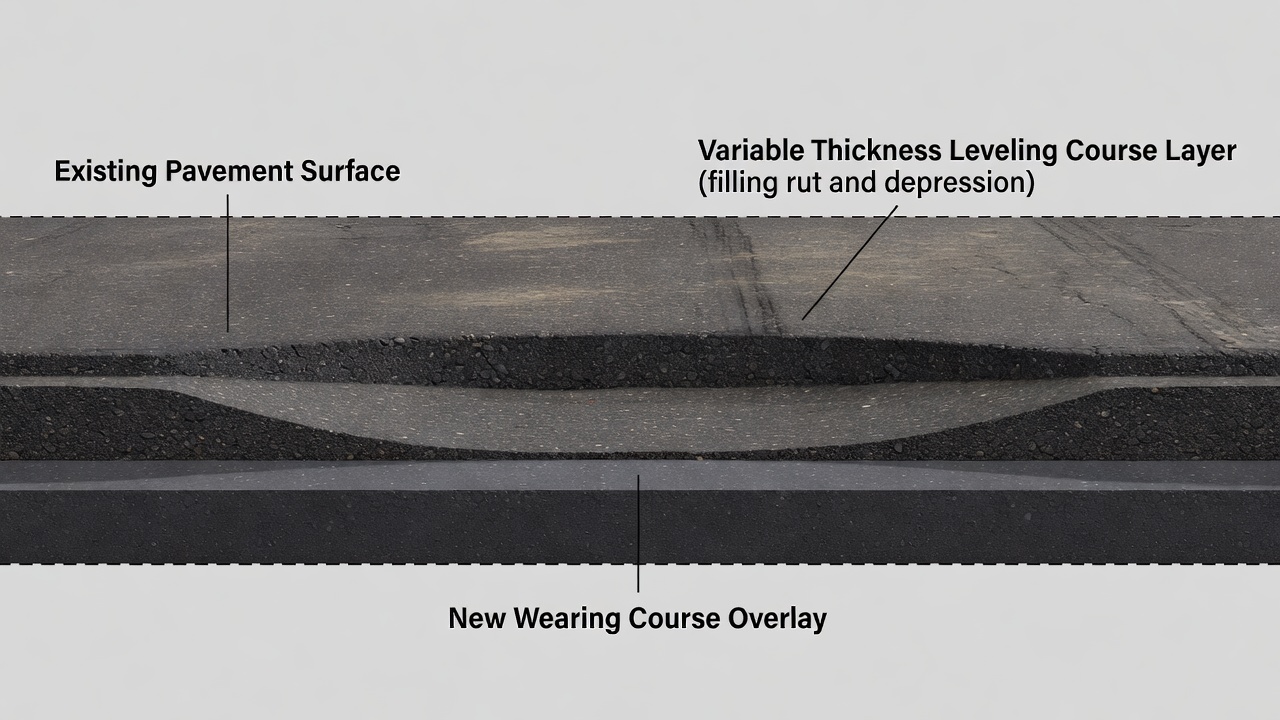
An asphalt leveling course is a layer of hot-mix asphalt (HMA) of variable thickness spread on an existing pavement surface to eliminate irregularities, restore proper cross-section, correct profile deficiencies, and provide a smooth, uniform platform prior to placing the final surface or wearing course. The leveling course is also referred to as a truing and leveling course, wedge course, binder leveling layer, or profile correction layer in different specifications and regional practices.
The FHWA defines the leveling course as “a course (asphalt aggregate mixture) of variable thickness used to eliminate irregularities in the contour of an existing surface” (FHWA Publication No. 01-4724, Principles of Construction of Quality HMA Pavements). The FAA defines it through Item P-401 of AC 150/5370-10H (Standard Specifications for Construction of Airports) as a course used for truing and leveling the existing pavement surface to restore proper cross-section prior to overlaying. The Asphalt Institute describes the leveling course as an intermediate layer placed to correct surface irregularities, fill depressions, restore crown and cross-slope, and provide uniform support for the final surface course (MS-22, Principles of Construction of Quality HMA Pavements).
The leveling course serves multiple critical functions in pavement rehabilitation. The primary function is profile correction — eliminating depressions, ruts, birdbaths, and undulations in the existing surface that would otherwise be reflected through the new overlay or would cause the overlay to be thicker than necessary at high spots and thinner than minimum at low spots. The second function is cross-slope restoration — re-establishing proper pavement crown and transverse slope to ensure adequate surface drainage. Standing water on pavement accelerates deterioration through moisture damage, hydroplaning risk on airfields, and freeze-thaw damage in cold climates. The third function is structural enhancement — while the leveling course is not primarily a structural layer, it does add thickness to the pavement structure that contributes to load distribution. The AAPTP Report 06-07 (Assessment of FAA HMA Overlay Procedures) confirms that the surface leveling course should be included with the determined overlay thickness when computing total structural capacity. The fourth function is reflective crack mitigation — the leveling course provides separation between existing cracks and the new surface course, delaying the propagation of reflective cracking through the overlay.
The leveling course also serves practical construction functions. It provides a smooth, uniform platform for the final surface lift, enabling the surface course paver to operate with consistent mat thickness and achieve superior ride quality. It reveals underlying deterioration during placement — if an area of the existing pavement fails under the weight of the paver and compaction equipment during leveling course construction, that area must be repaired before the final overlay is placed. This early detection of subsurface problems prevents future pavement failures that would require costly remedial work. The leveling course also provides a payment mechanism for contractors — by specifying a leveling course as a separate pay item at a per-ton rate, the contractor is compensated for the additional material required for grade corrections rather than absorbing the cost through unexpected overruns in the surface course material quantity.
When a Leveling Course is Needed
A leveling course is required whenever an existing pavement surface has irregularities that exceed specified tolerances for overlay placement. The FAA specifies in AC 150/5370-10H that profile correction is required when existing pavement surface deviations exceed ±9 mm (3/8 inch) when tested with a 3.7-meter (12-foot) straightedge. This tolerance applies to both longitudinal and transverse directions.
Specific conditions that trigger the need for a leveling course include rutting — when existing pavement rut depth exceeds 6 mm (1/4 inch), the ruts must be filled to prevent them from reflecting through the overlay or causing the overlay to have reduced thickness in the rut path. Depressions and birdbaths — areas where water ponds after rainfall indicate localized settlement that must be filled by a leveling course to restore positive drainage. Cross-slope deficiencies — when the existing pavement cross-slope does not meet design requirements (minimum 1.5% for roads, 1.0% to 1.5% for airport runways per FAA and ICAO standards), a wedge-shaped leveling course that varies from zero thickness at one edge to design thickness at the opposite edge restores proper drainage slope. ADA compliance corrections — leveling courses are used to correct parking lot slopes and walkway cross-slopes to meet Americans with Disabilities Act requirements, which mandate a maximum cross-slope of 2% in any direction. Transition zones — where a pavement section is being overlaid and adjacent sections at different elevations require a feather-edge leveling course transition.
A leveling course is always required on rubblized Portland cement concrete pavements before asphalt overlay placement. The FAA addresses this specifically in AC 150/5320-6G (Airport Pavement Design and Evaluation), Section 3.5: “An aggregate leveling course of P-209 will minimize any difficulties with a rubblized surface being rough or uneven.” The rubblization process breaks the existing concrete slab into pieces ranging from 150 to 300 mm (6 to 12 inches) in maximum dimension, creating an inherently uneven surface that cannot serve as a direct platform for asphalt paving. The leveling course on rubblized PCC can be an asphalt leveling course (P-401 Gradation 3 or P-403) or an aggregate leveling course (P-209 crushed aggregate base).
The decision to use a leveling course versus milling alone depends on the elevation constraint of the project. If the existing pavement elevation cannot be raised (due to bridge clearances, curb reveals, drainage inlet elevations, runway edge lighting fixtures, or building access thresholds), milling is used to remove material and create space for the overlay. If the elevation can be raised, a leveling course followed by an overlay is the more economical approach because it avoids the cost of milling and material hauling. In practice, many projects use a combination of milling and leveling course — milling removes the upper 25 to 50 mm of deteriorated surface material and corrects major profile deficiencies, while the leveling course fills remaining low spots and provides the final smooth surface before the structural overlay.
The ICAO Aerodrome Design Manual, Part 3 — Pavements (Doc 9157) provides international guidance on when a leveling course is needed in airport pavement rehabilitation. The Manual specifies that the existing pavement surface should be prepared by “repairing cracks, patching spalled areas, and applying a leveling course where necessary to provide a uniform surface for the overlay.” ICAO recognizes that the leveling course may be included in the structural overlay thickness if it contributes to the total pavement structural capacity, but if used solely for profile correction, it is not counted toward the required structural thickness.
Material Selection — Fine-Graded Mix and Workability
The material selection for a leveling course is governed by the requirement for a fine-graded, workable mix that can be placed in thin, variable-thickness lifts while achieving adequate compaction and surface smoothness. The FAA specifies Gradation 3 as the designated gradation for leveling courses under Item P-401 and Item P-403 in AC 150/5370-10H. The FAA Engineer’s Note to the specification is explicit: “The Engineer is only to specify Gradation 3 for leveling course, airfield shoulders, and roadways.”
Property
FAA Gradation 3 Specification
Nominal Maximum Aggregate Size (NMAS)
12.5 mm (1/2 inch)
Maximum Aggregate Size
19 mm (3/4 inch)
Asphalt Binder Content (stone/gravel)
5.5% to 8.0% by weight of total mix
Asphalt Binder Content (slag)
7.0% to 10.5%
Minimum Voids in Mineral Aggregate (VMA)
16.0%
Design Air Voids
3.5%
Minimum Compacted Lift Thickness (Table 2, AC 150/5370-10H)
38 mm (1.5 inches)
Recommended Minimum Lift Thickness (4x NMAS per FAA HQ AAS-100)
50 mm (2 inches)
Absolute Minimum Lift Thickness (3x NMAS)
38 mm (1.5 inches)
The gradation requirements for FAA Gradation 3 are: 100% passing the 12.5 mm (1/2-inch) sieve, 90% to 100% passing the 9.5 mm (3/8-inch) sieve, 58% to 78% passing the 4.75 mm (No. 4) sieve, 40% to 60% passing the 2.36 mm (No. 8) sieve, 18% to 38% passing the 600 µm (No. 30) sieve, 11% to 27% passing the 300 µm (No. 50) sieve, 6% to 18% passing the 150 µm (No. 100) sieve, and 3% to 6% passing the 75 µm (No. 200) sieve. This fine-graded distribution provides a high surface area that requires higher binder content than coarser mixes, producing a mix that is workable, placeable in thin lifts, and capable of achieving a smooth surface finish.
The asphalt binder selection for leveling courses follows the same PG (Performance Grade) selection process as other pavement courses, with additional consideration for thin-lift placement conditions. Per FAA AC 150/5370-10H Section 401-2.3, the starting PG grade is selected consistent with state DOT requirements for the environmental conditions at the project location. A grade bump is then applied based on aircraft gross weight. For pavements serving aircraft with gross weight of 30,000 to 100,000 lbs (13,600 to 45,400 kg), a one-grade bump is applied to the high-temperature grade. For aircraft exceeding 100,000 lbs (45,400 kg), a two-grade bump is applied to the high-temperature grade, or a three-grade bump for slow/stationary loading conditions (aircraft parking positions, holding aprons). The resulting binder grade for a leveling course at a major commercial airport would typically be PG 76-22 or PG 70-28, depending on the climate zone.
The Marshall mix design criteria for FAA P-401 leveling course (aircraft gross weight exceeding 60,000 lbs) are: compaction at 75 blows per face, minimum stability of 2,150 lbs (9.6 kN), flow range of 8 to 14 (0.25 mm units), air voids of 3.5%, minimum VMA of 16.0% for 12.5 mm NMAS, minimum Tensile Strength Ratio (TSR) of 80% at 70% to 80% saturation (AASHTO T283), maximum APA rut depth of 10 mm at 4,000 passes at 250 psi and 64°C, or Hamburg wheel tracking of 10 mm maximum at 20,000 passes at 50°C. For pavements with aircraft gross weight below 60,000 lbs, the P-403 specification applies with compaction at 50 blows per face, stability minimum of 1,350 lbs, flow of 10 to 14, and air voids of 2.8% to 4.2%.
The workability characteristics of Gradation 3 make it the preferred choice for leveling courses. The fine aggregate content (high percentage passing the No. 4 sieve) provides a mix that is easily manipulated by hand raking at transverse joints and tapered edges — areas where mechanical placement cannot achieve the precise feather-edge transition required. The higher binder content (5.5% to 8.0% compared to 4.5% to 7.0% for Gradation 2) provides greater mixture cohesion and workability, allowing the mix to be spread evenly at varying thicknesses without raveling or segregation. The small maximum particle size (12.5 mm) minimizes the risk of aggregate sticking proud of the surface at minimum lift thickness locations, producing a smooth surface texture that provides an ideal bonding substrate for the tack coat and subsequent overlay.
Automatic Grade Control Systems
Automatic grade control is the key technology that enables the placement of a variable-thickness leveling course with precision and efficiency. Without automatic grade control, the paver screed would follow the existing irregular surface, reproducing the same bumps and depressions in the new leveling course. Automatic grade control systems use sensors to continuously adjust the screed tow points, maintaining the screed at a controlled elevation relative to a reference, so that low spots are filled and high spots are skimmed.
Averaging Beam
The averaging beam is the most common method for leveling course grade control. A rigid beam of 9.1 meters (30 feet) is mounted on the paver, extending forward from the screed. Sonic (ultrasonic) sensors ride on top of the beam and reference the average elevation of the existing surface over the beam length. The beam mechanically averages out short-wave irregularities — typically undulations shorter than the beam length — while allowing the paver to follow the general grade trend. A 30-foot averaging beam effectively smooths out bumps and depressions up to approximately 0.5 inches in amplitude. The paver screed follows this averaged reference, automatically filling low spots and reducing thickness over high spots. Sonic averaging beams produce the smoothest mat for leveling course placement because they smooth out short-wave irregularities without requiring a stringline setup. The accuracy of sonic averaging beam systems is ±3 mm (1/8 inch) .
Mobile Ski
The mobile ski (also called a traveling ski or mobile reference) is a rigid beam, typically 3 to 9 meters (10 to 30 feet) in length, with sliding shoes at each end that ride directly on the existing pavement surface. The grade sensor references the top of the ski, following the existing contour while averaging out short irregularities. The ski is effective when the existing surface has a consistent overall grade but localized bumps and depressions. Shorter skis (3 to 4.5 meters) follow the existing contour more closely and are used when minimal profile change is desired. Longer skis (6 to 9 meters) produce a smoother mat by averaging over a greater distance but may not correct large-scale grade deviations as effectively.
Stringline
The stringline method provides the most accurate profile correction capability for leveling course placement. A steel wire or nylon string is set on stakes at precise grade elevations, positioned at a fixed offset — typically 0.6 to 1.2 meters (2 to 4 feet) — from the paver travel path. The grade sensor on the paver follows the stringline for absolute elevation control. Stringline stake spacing is 7.6 to 15.2 meters (25 to 50 feet) maximum, with string tension of 25 to 50 lbs for steel wire to prevent sag between stakes. The height tolerance for stringline installation is ±1.5 mm (1/16 inch) . Stringline is essential where new grade must match design elevations exactly — particularly at locations with NAVAIDS, in-pavement lighting, or fixed elevation constraints on airfields. The stringline method is labor-intensive to set up but provides the best results for major profile corrections.
3D Machine Control
Three-dimensional machine control is the most advanced grade control method, using a digital 3D design model of the finished pavement surface combined with GPS or robotic total station positioning to control the paver screed automatically. GPS receivers provide broad-area positioning with vertical accuracy of ±20 to 30 mm, while robotic total stations provide higher precision at ±3 to 5 mm. The onboard computer compares the paver’s actual position to the design surface and commands hydraulic cylinders at the screed tow points to adjust for the required variable depth. This system can pave a variable-thickness mat automatically based on the 3D design, eliminating the need for stringline stakes — a significant advantage for airfield operations where stakes on runways and taxiways present foreign object debris (FOD) hazards. Trimble Roadworks Paving Control Platform and Topcon 3D Paving Systems are the industry leaders in 3D paving control. These systems also provide real-time as-built recording of the actual placed surface, generating production reports with thickness and elevation data for quality control documentation.
Variable Thickness Placement
The leveling course varies in thickness across the paving mat — from zero at high spots to the design thickness at low points — which creates unique placement challenges that distinguish it from uniform-thickness overlay construction.
The thickness variation within a single paver pass can range from 12 mm (0.5 inch) to 75 mm (3 inches) or more. At the tapered edges where the leveling course transitions to zero thickness, the mix must be feathered to a smooth, uniform edge without raveling or segregation. This feather-edge construction is achieved through hand raking at the transverse joints and by the paver’s automatic grade control at the longitudinal edges.
Screed adjustment is critical to variable thickness placement. The paver screed must be continuously adjusted to maintain the correct angle of attack — the angle between the screed plate and the mat surface. Thicker sections require a greater screed angle to achieve adequate pre-compaction, while thinner sections require a reduced screed angle. Automatic grade control systems handle these adjustments in real-time, but the paver operator must monitor the screed response and make manual adjustments when the automatic system reaches its correction limits.
Paving speed for leveling courses is typically 2.4 to 4.6 meters per minute (8 to 15 feet per minute) — slower than standard overlay paving speeds of 3 to 6 m/min (10 to 20 ft/min). The slower speed allows the screed to respond to grade changes more gradually, prevents tearing of the thin mat at the tapered edges, and provides more time for the roller operators to complete compaction before the mat cools.
Longitudinal joint construction for leveling courses follows the same principles as standard overlay joints but with additional care at the tapered edges. Hot joints — adjacent lanes placed within 15 minutes of each other — provide the best bond and prevent a cold joint line. Cold joints — when the adjacent lane is placed more than 4 hours later or the existing mat has cooled below 71°C (160°F) — must be cut back to a straight vertical edge and the vertical face coated with tack coat before the next lane is placed.
Transitions and taper rates must be designed to avoid abrupt thickness changes that create ride quality issues. The maximum taper rate is typically 1:50 (2% grade change per longitudinal meter) . For example, transitioning from a 40 mm leveling course thickness to zero thickness requires a minimum transition length of 2 meters (6.6 feet). Hand raking is required at transverse joints and tapered edges to achieve the smooth feather-edge transition.
When total required leveling course thickness exceeds the maximum per lift — typically 75 mm (3 inches) for Gradation 3 based on the 6x NMAS rule — the leveling course is placed in multiple lifts. Each lift is independently compacted and accepted before the next lift is placed, and a tack coat is applied between lifts. For thicker lower lifts, a coarser gradation (FAA Gradation 2, 19 mm NMAS) can be used for structural efficiency, with Gradation 3 used only for the final leveling lift to achieve the required surface smoothness.
Leveling Course Compaction
Compaction of a thin, variable-thickness leveling course presents unique challenges that distinguish it from standard overlay compaction. Thin sections lose heat rapidly, preventing the mix from achieving its target density if compaction is not initiated quickly. The variable thickness means that adjacent areas of the same mat are at different temperatures and require different compaction effort. Roller bridging — where the roller span crosses a low spot without applying adequate compactive force — can leave thin areas undercompacted.
The FAA temperature requirements for leveling course compaction are specified in AC 150/5370-10H Table 4. For lifts 25 mm (1 inch) or less, the minimum base surface temperature is 10°C (50°F) . For lifts greater than 25 mm but less than 75 mm (1 to 3 inches), the minimum base temperature is 7°C (45°F) . These temperature minimums are higher than for thicker structural lifts (4°C or 40°F for lifts 75 mm and greater) because thin lifts lose heat to the underlying pavement surface more rapidly, and a warmer base surface helps maintain mix temperature for compaction.
The roller train for leveling course compaction must be positioned closer to the paver than for standard overlay compaction. For lifts 38 mm (1.5 inches) or less, the breakdown roller must stay within 15 to 30 meters (50 to 100 feet) of the paver. For lifts 25 mm (1 inch) or less, rolling must begin immediately behind the paver — there is no buffer zone. The recommended roller train consists of: a 10 to 12 ton steel vibratory roller for breakdown rolling (2 to 4 passes with vibration on, amplitude reduced for thin lifts), a 15 to 25 ton pneumatic-tire roller for intermediate rolling (3 to 6 passes with kneading action to seal the surface and increase density), and an 8 to 12 ton static steel roller for finish rolling (2 to 4 passes with vibration off to remove roller marks). For very thin lifts under 19 mm (3/4 inch), vibration should not be used at all to prevent aggregate degradation.
The FAA density target for leveling courses per the current AC 150/5370-10H (new specification) is 94.5% of laboratory density as determined from a control strip, with joint density of 92.5% . Under the older P-401/P-403 specification still referenced in many project documents, the target is 98% of laboratory density (Marshall) for mat density and 95% for joint density. The newer specification uses Percent Within Limits (PWL) acceptance criteria rather than absolute minimum density. The design air void target is 3.5% ± 1% for P-401 and 2.8% to 4.2% for P-403.
Density testing of thin lifts presents technical challenges. Nuclear density gauges have a fixed depth of measurement — typically 50 to 75 mm (2 to 3 inches) — meaning that for lifts thinner than 50 mm, the gauge reading includes density contribution from the underlying layer. Thin-lift nuclear gauges with special calibration for reduced measurement depth are available. Core sampling of very thin lifts (under 25 mm) is problematic because the core may break during extraction. Non-nuclear density gauges using electromagnetic methods can provide relative measurements for quality control, and roller-mounted continuous compaction control (CCC) or intelligent compaction (IC) systems provide real-time density mapping of the entire mat area.
Inspection of Leveling Course
Quality control and acceptance inspection of the leveling course focuses on thickness, profile, density, and surface smoothness. The leveling course acceptance typically has relaxed smoothness requirements compared to the final surface course, recognizing that its purpose is to correct the existing surface irregularities, not to provide the final riding surface.
Thickness measurement is performed by core sampling at a minimum frequency of 5 cores per lot (1 per sublot) at random locations per ASTM D3665. Core thickness is measured per ASTM D3549. All core holes must be filled by the contractor. Non-destructive thickness profiling using Ground Penetrating Radar (GPR) is also accepted by many agencies, providing continuous thickness data across the entire paved area. GPR can detect thickness variations, delaminations, and voids that would not be identified by discrete coring. The FAA grade tolerance for leveling course thickness is ±15 mm (0.05 feet) of the specified grade elevation.
Profile verification uses the 3.7-meter (12-foot) straightedge per FAA P-401. The straightedge is applied parallel to and at right angles to the centerline, moved continuously forward at half the length of the straightedge. The maximum deviation tolerance for the leveling course is ±9 mm (3/8 inch) — the same tolerance that triggered the need for leveling in the first place. Once the leveling course achieves this tolerance, the final surface course is placed over it to achieve final smoothness acceptance, which uses the California-type profilograph with a 6 mm (1/4-inch) simulation for FAA projects. The International Roughness Index (IRI) target for airport pavements is typically less than 60 to 80 inches per mile.
Density acceptance follows the lot-based statistical sampling plan. Each lot equals one shift or a specified tonnage (typically 1,500 to 3,000 tons), divided into sublots of 250 to 500 tons each. One core is taken per sublot at a random location. The density and air voids of each core are measured in the laboratory. Acceptance is based on Percent Within Limits (PWL) — a minimum of 90% PWL is typically required for full payment, with reduced payment for PWL between 80% and 90% and required removal and replacement for PWL below 80%.
Leveling Course in Airport Overlay Projects
Airport overlay projects require careful attention to leveling course specifications due to the stringent safety requirements, high tire pressures, and the need to maintain precise grade elevations at runway lighting systems, navigational aids, and pavement edge fixtures.
The FAA framework for leveling courses in airport construction is established through Item P-401 (Hot Mix Asphalt Pavement) and Item P-403 (Plant Mix Pavement) in AC 150/5370-10H. For heavy aircraft pavements (aircraft gross weight exceeding 30,000 lbs or 13,600 kg), the leveling course can be specified under either P-401 or P-403. For lighter pavements (aircraft gross weight of 12,500 lbs or less) and for roads, shoulders, and blast pads, the leveling course is specified under P-403. The FAA Engineer’s Note states: “For courses other than the surface course, such as stabilized base courses, asphalt binder courses and/or truing and leveling courses… specification Item P-403 may be used.”
The FAA AC 150/5320-6G (Airport Pavement Design and Evaluation) provides specific guidance on leveling courses in the context of pavement rehabilitation. Section 3.5 addresses aggregate leveling course on rubblized pavement: “An aggregate leveling course of P-209 will minimize any difficulties with a rubblized surface being rough or uneven.” Section 4.10 addresses preparation of the existing pavement surface for an overlay, discussing cold milling, full-depth removal of distressed areas, crack sealing, and the use of asphalt leveling course to address surface irregularities.
The AAPTP Report 06-07 (Assessment of FAA HMA Overlay Procedures) categorizes the surface leveling course under “Modification of Existing HMA Pavement” along with cold milling and surface recycling. The report specifies that when a leveling course is used, it should be included with the determined overlay thickness in the structural design — meaning the leveling course thickness is added to the structural overlay thickness, not treated as a separate non-structural element. This is an important distinction because it affects the total pavement thickness and structural capacity calculations in FAARFIELD.
The Los Angeles World Airports (LAWA) Special Provisions for P-401 and P-403 provide specific requirements for leveling courses at major commercial airports. The P-401 surface course provision states: “The truing and leveling course shall not exceed a nominal thickness of 1-1/2 inches (38 mm). The leveling course is the first variable thickness lift of an overlay placed.” For P-403 leveling course, LAWA specifies maximum aggregate size not more than one-half of the course thickness, maximum 15% natural sand by weight of total aggregate, and minimum sand equivalent of 45.
The FAA HQ AAS-100 lift thickness guidance (Washington State DOT interpretation document, January 20, 2016) provides the authoritative interpretation of minimum and maximum lift thickness for airport leveling courses. The document confirms: “AC 150/5370-10G Item P-401 paragraph 401-3.2 recommends that the aggregate size be no greater than 1/4 the lift thickness to be constructed. This indicates a minimum lift thickness at least 4 × the largest actual particle size; which can generally be considered 4 × NMAS.” For FAA Gradation 3 (1/2-inch NMAS), this gives: recommended minimum lift thickness of 50 mm (2 inches) , absolute minimum lift thickness of 38 mm (1.5 inches) based on 3x NMAS, and maximum recommended lift thickness of 75 mm (3 inches) based on 6x NMAS. The guidance states: “It is never recommended to use a lift thickness less than 3 × NMAS; and generally want to keep maximum lift thickness less than 6 × NMAS.”
ICAO Doc 9157 (Aerodrome Design Manual, Part 3 — Pavements) provides international guidance for leveling courses on airport pavements. The key points from ICAO guidance include: the existing pavement surface should be prepared by repairing cracks, patching spalled areas, and applying a leveling course where necessary to provide a uniform surface for the overlay; the leveling course should use a fine-graded asphalt mix that can be placed in thin, variable-thickness lifts; a tack coat should be applied to the existing surface before placing the leveling course and between leveling course lifts; and the leveling course thickness is not included in the structural overlay thickness if used solely for profile correction, but if it contributes structurally, it may be included.
Leveling Course Thickness Limitations
The thickness of a leveling course per lift is governed by the aggregate size and the compaction capability of the mix. The fundamental rule is that the lift thickness must be at least 3 times the nominal maximum aggregate size, with 4 times the NMAS being the recommended minimum. For FAA Gradation 3 with 12.5 mm NMAS, this establishes the following thickness boundaries:
Factor
Value
Source
Recommended minimum lift thickness (4x NMAS)
50 mm (2.0 inches)
FAA HQ AAS-100 guidance
Absolute minimum lift thickness (3x NMAS)
38 mm (1.5 inches)
FAA “never-recommend-below” threshold
Maximum recommended lift thickness (6x NMAS)
75 mm (3.0 inches)
FAA lift thickness guidance
FAA Table 2 minimum compacted lift
38 mm (1.5 inches)
AC 150/5370-10H, Table 2
LAWA nominal maximum thickness
38 mm (1.5 inches)
LAWA Special Provisions, P-401
Aggregate size fraction of lift thickness
≤ 1/4 of lift thickness
FAA P-401, §401-3.2
The minimum thickness is driven by the need to have enough mix depth to allow the aggregate particles to rearrange and interlock during compaction. If the lift is too thin relative to the aggregate size, the roller cannot achieve the particle movement necessary for densification, and the larger aggregates will be pressed into the underlying surface rather than being embedded in the mix. The maximum thickness is driven by the need to achieve uniform compaction throughout the lift depth — in lifts thicker than 6 times NMAS, the upper portion of the lift may over-compact (excessively low air voids) while the lower portion remains under-compacted (excessively high air voids).
When the total required leveling course thickness exceeds the maximum per lift, construction in multiple lifts is required. Each lift is placed, compacted, and accepted before the next lift is placed. A tack coat is applied between lifts. For projects requiring total leveling course thickness of 75 to 150 mm (3 to 6 inches), the lower lifts can use FAA Gradation 2 (19 mm NMAS, 50 mm minimum lift thickness) for structural efficiency, with the final leveling lift using Gradation 3 (12.5 mm NMAS, 38 mm minimum lift thickness) for surface smoothness.
Tack Coat for Leveling Course Interface
Proper tack coat application between the existing pavement surface and the leveling course — and between leveling course lifts — is essential for interlayer bond and long-term overlay performance. The tack coat creates a uniform, adhesive interface that bonds the leveling course to the existing pavement and prevents relative horizontal movement (slippage) between layers.
FAA Item P-603 (Emulsified Asphalt Tack Coat) specifies the materials and application rates. The residual asphalt application rates vary by surface condition: 0.04 to 0.06 gallons per square yard for new asphalt or between HMA lifts, 0.06 to 0.10 gal/yd² for existing milled asphalt surfaces, 0.05 to 0.08 gal/yd² for existing unmilled asphalt surfaces, and 0.08 to 0.12 gal/yd² for Portland cement concrete surfaces. The higher rates for milled surfaces reflect the greater surface area created by the milling texture. The FAA specifies SS-1, SS-1h, CSS-1, or CSS-1h emulsified asphalt for tack coat, typically diluted with water at a 1:1 ratio.
The FHWA TechBrief on Tack Coat Best Practices (FHWA-HIF-16-017) emphasizes that required application values should be in terms of residual asphalt application rates — the asphalt content remaining after the water in the emulsion has evaporated. The dilution factor must be accounted for when specifying the emulsion application rate. Application temperature for tack coat is typically 60°C to 82°C (140°F to 180°F) . The tack coat must not be applied when the surface temperature is below 10°C (50°F) , and the emulsion must be fully cured (broken) — changed from brown to black color — before the leveling course is placed.
Alternatives to Leveling Course
Several alternatives to the leveling course exist, each with specific applications and limitations. The selection of alternative depends on the existing pavement condition, elevation constraints, project budget, and performance requirements.
Cold planing (milling) is the most common alternative, using a rotating drum with carbide-tipped cutting teeth to mechanically remove the existing pavement surface to a specified depth. Milling depth typically ranges from 25 to 150 mm (1 to 6 inches) . Profile milling can vary depth within a single pass to correct grade. The advantages over leveling course are: corrects profile without adding thickness (maintains existing elevation), removes distressed surface material, eliminates reflective cracking potential from the upper surface layer, and provides a textured surface for bond with the overlay. The disadvantages are: does not add structural capacity, generates Reclaimed Asphalt Pavement (RAP) material requiring handling, may expose underlying distress, and has higher initial equipment cost.
Micro-milling uses a specialized milling drum with 118 to 168 cutting teeth — significantly more than the standard 48 to 80 teeth — producing a smooth, uniform texture comparable to diamond grinding. Micro-milling removes 12 to 38 mm (0.5 to 1.5 inches) with a texture depth of 1.6 to 4.8 mm (1/16 to 3/16 inch) . The fine-textured surface can serve as an excellent bonding surface for a thin overlay without requiring a leveling course. Micro-milling improves friction characteristics and reduces hydroplaning risk, making it particularly suitable for airport runways.
Diamond grinding uses a rotating drum with diamond-impregnated blades, originally developed for PCC pavements. It creates longitudinal grooves typically 3 to 6 mm (1/8 to 1/4 inch) deep and 2 to 3 mm (0.08 to 0.12 inch) wide at 12 to 18 mm (0.5 to 0.7 inch) spacing. Diamond grinding restores smoothness and friction on PCC pavements before asphalt overlay but is less common for asphalt pavements (micro-milling is preferred for asphalt).
High-Performance Thin Overlay (HPTO) is a specialized thin HMA surface course placed at 12 to 38 mm (0.5 to 1.5 inches) using fine-graded, polymer-modified mixes. HPTO can be placed directly on a properly prepared (milled) surface without a separate leveling course, using 9.5 mm or 12.5 mm NMAS mixes with polymer-modified binders. The FHWA HPTO specifications require minimum lift thickness of 2x NMAS.
Important note: On crack-and-seat and rubblized PCC pavements, a leveling course is always required. Neither milling nor HPTO alone provides the thick, uniform platform needed to bridge the rough, uneven surface of fractured concrete slabs. The FAA AC 150/5320-6G Section 3.5 requires an aggregate leveling course of P-209 or asphalt leveling course of P-401/P-403 on rubblized surfaces, regardless of the final overlay design.
Alternative
Profile Correction
Structural Addition
Surface Texture
Cost
Reflective Crack Control
Leveling Course
Excellent
Yes (partial)
Good
Moderate
Good
Cold Planing
Excellent
No (removes material)
Fair
High
Good (removes cracks)
Micro-Milling
Good (shallow only)
No (removes material)
Excellent
High
Moderate
Diamond Grinding
Good (minor correction)
No (removes material)
Very Good
Very High
Poor
HPTO
Fair
Yes (thin)
Excellent
High
Fair
Crack & Seat + Leveling Course
Requires leveling course
Yes
—
Very High
Excellent
Leveling Course in Pavement Management Systems
In the context of pavement management and inspection, the presence of a leveling course in a pavement’s layer structure provides important information about the pavement’s rehabilitation history. When a leveling course has been placed, it indicates that the pavement surface had significant profile irregularities at the time of the last overlay — rutting deeper than 6 mm, depressions requiring filling, or cross-slope deficiencies needing correction. This information is valuable for diagnosing current pavement conditions: if a pavement with a documented leveling course develops similar distress patterns (rutting, birdbaths) in the same locations, the underlying issue is likely subgrade or base failure rather than surface wear.
Inspectors should note leveling course presence, thickness variation, and condition during pavement condition surveys. The Pavement Condition Index (PCI) methodology (ASTM D5340 for airports, ASTM D6433 for roads) does not have a specific distress category for leveling course failure, but leveling course-related distress manifests as: delamination (separation between leveling course and surface course) indicated by peeling or a hollow sound when tapped, slippage cracking (crescent-shaped cracks indicating horizontal movement at the leveling course interface), and reflective cracking from the existing pavement through the leveling course and into the surface course. Accurate documentation of leveling course construction history — date placed, mix type, nominal thickness, grade control method used — enables better diagnosis of these distress patterns and more informed overlay rehabilitation design for the next overlay cycle.
For the ACR-PCR method (Aircraft Classification Rating — Pavement Classification Rating) adopted by ICAO in 2020, the leveling course layer must be accurately represented in the pavement structure model used for PCR computation. The layer thickness, material type, and modulus directly affect the computed PCR value. If a leveling course was placed but not documented in the pavement management records, the PCR calculation may overestimate or underestimate the pavement’s true load-carrying capacity. This makes accurate leveling course documentation essential for airport pavement management systems that support the ICAO ACR-PCR reporting requirements.
Frequently Asked Questions
A leveling course is a variable-thickness layer of hot-mix asphalt placed on an existing pavement surface to correct irregularities such as depressions, ruts, birdbaths, and cross-slope deficiencies before the final surface course (wearing course) is placed. It is typically 15 to 40 mm thick and uses a fine-graded mix with 1/2-inch nominal maximum aggregate size (FAA Gradation 3) to allow placement in thin, variable-thickness lifts. The leveling course is placed using automatic grade control systems — averaging beams, skis, stringlines, or 3D GPS machine control — that adjust the paver screed to fill low spots and trim high spots. It is distinct from a structural overlay in that its primary purpose is profile correction rather than adding structural capacity, though it does contribute some additional thickness to the pavement structure.
A leveling course is needed when the existing pavement surface has irregularities exceeding ±9 mm (3/8 inch) under a 3.7-meter (12-foot) straightedge per FAA AC 150/5370-10H. Specific conditions requiring a leveling course include: rutting deeper than 6 mm (1/4 inch), depressions where water ponds (birdbaths), areas requiring cross-slope restoration for drainage, transitions between pavement sections at different elevations, surfaces where milling alone cannot fully correct the profile, and rubblized Portland cement concrete pavements that require a smooth platform for the overlay. On crack-and-seat and rubblized PCC projects, an aggregate leveling course of P-209 crushed aggregate base or an asphalt leveling course of P-401/P-403 is always required because the rubblized surface is inherently rough and uneven.
The FAA specifies Gradation 3 (1/2-inch nominal maximum aggregate size) for leveling courses under Item P-401 and P-403 in AC 150/5370-10H. This fine-graded mix has asphalt binder content of 5.5% to 8.0% by weight of total mix for stone and gravel aggregates, minimum VMA of 16.0%, and design air voids of 3.5%. The fine gradation provides better workability in thin variable-thickness lifts, easier hand placement in confined areas and tapered edges, less segregation at varying depths, and improved compaction at the thinner lift thicknesses typical of leveling courses. The lift thickness rule for this mix is a minimum of 4 times the nominal maximum aggregate size (50 mm or 2 inches recommended) and never less than 3 times NMAS (38 mm or 1.5 inches absolute minimum).
A leveling course is placed using a tracked asphalt paver equipped with automatic grade control systems. The most common method uses a 9.1-meter (30-foot) averaging beam with sonic sensors that reference the average surface elevation, allowing the paver to fill low spots and skim over high spots automatically. For projects requiring precise grade control, a stringline set to design elevations provides the most accurate profile correction. Three-dimensional machine control systems using GPS or robotic total stations with a 3D design model can pave variable-thickness mats automatically without stringline stakes. The paver operates at 2.4 to 4.6 m/min (8 to 15 ft/min) during leveling course placement, and the mat is compacted immediately behind the paver — within 15 to 30 meters (50 to 100 feet) — because thin lifts cool rapidly.
Leveling course compaction presents unique challenges because the lift is thin (typically 25 to 40 mm) and varies in thickness across the mat. Thin sections lose heat rapidly, so the breakdown roller must stay within 15 to 30 meters (50 to 100 feet) of the paver for lifts at or below 38 mm (1.5 inches). For lifts at or below 25 mm (1 inch), rolling must begin immediately behind the paver. The FAA requires a minimum base surface temperature of 10°C (50°F) for lifts of 25 mm (1 inch) or less. Vibratory amplitude must be reduced for thin lifts under 38 mm to avoid aggregate degradation, and vibration should not be used on lifts under 19 mm (3/4 inch). Target mat density per FAA P-401 is 94.5% of laboratory density for the newer AC 150/5370-10H specification or 98% for older P-401/P-403 specifications. More rollers may be required to complete compaction before the thin mat cools below the minimum compaction temperature of 104°C (220°F).
Alternatives to a leveling course include: cold planing (milling) — mechanical removal of 25 to 150 mm of existing pavement to correct profile, which removes distressed material but adds no structural thickness; micro-milling — using a high-density milling drum (118 to 168 teeth) to remove 12 to 38 mm with a very smooth texture that can serve directly as a bonding surface; diamond grinding — rotating diamond-impregnated blades for PCC pavements to restore smoothness and friction; and high-performance thin overlay (HPTO) — specialized polymer-modified thin HMA placed at 12 to 38 mm directly on a milled surface. On crack-and-seat and rubblized PCC projects, a leveling course is always required regardless of milling or grinding — the alternatives do not eliminate the need for profile correction on these rough surfaces. The choice between leveling course and milling depends on whether the existing pavement elevation can be raised (leveling course adds thickness) or must be maintained (milling removes material to make room for the overlay).
A leveling course and a binder course serve different purposes in pavement construction. A leveling course is a variable-thickness layer (typically 15 to 40 mm) placed to correct surface irregularities, depressions, and cross-slope deficiencies — its purpose is profile correction, not structural load distribution. A binder course (also called intermediate course or base course of an asphalt system) is a uniform-thickness structural layer placed between the base and wearing course to distribute loads and provide additional thickness. The binder course has a coarser gradation (typically 19 mm or 3/4-inch NMAS) and is placed at consistent thickness, typically 50 to 100 mm per lift. The leveling course uses a finer-graded mix (12.5 mm or 1/2-inch NMAS) for workability in thin variable lifts. In airport construction, the FAA specifies Gradation 3 (1/2-inch max) for leveling courses and Gradation 1 (1-inch max) or Gradation 2 (3/4-inch max) for structural binder courses.
Optimize Your Pavement Rehabilitation Planning
Understanding leveling course requirements is essential for accurate overlay design and construction cost estimation. Our pavement inspection and data analysis services identify profile deficiencies that require leveling courses before overlay placement. Contact us to discuss your pavement rehabilitation project needs.
An asphalt overlay is the placement of one or more new HMA layers over an existing pavement to restore structural capacity, improve ride quality, and/or enhance...
The wearing course, also called the surface course, is the uppermost pavement layer directly exposed to traffic, designed to provide friction, smoothness, water...
The base course is a load-distributing layer of high-quality aggregate or stabilized material placed between the subbase (or subgrade) and the asphalt or concre...
29 min read
Pavement layer
Airport construction
+3
Cookie Consent We use cookies to enhance your browsing experience and analyze our traffic. See our privacy policy.