Light Weight Deflectometer (LWD) for Construction QC
The Light Weight Deflectometer (LWD) is a portable non-destructive testing device that drops a known weight onto a loading plate to measure surface deflection and estimate the dynamic deformation modulus (ELWD) of compacted soils and aggregates. It is used for rapid compaction quality control, subgrade evaluation, and base course acceptance testing in road and airport construction.
Light Weight Deflectometer — Definition and Portability
The Light Weight Deflectometer (LWD) is a portable, non-destructive testing device engineered for the in-situ evaluation of the stiffness and load-bearing capacity of compacted soils, unbound granular materials, and thin asphalt pavements. It belongs to the family of deflectometer devices that includes the Falling Weight Deflectometer (FWD) , Heavy Weight Deflectometer (HWD) , Rolling Weight Deflectometer (RWD) , and Dropping Weight Deflectometer (DWD) , but distinguishes itself through its hand-portable, single-person operational design. The LWD was first conceptualized and developed in 1981 by the Federal Highway Research Institute (FHRI) in collaboration with the Headquarters of Magdeburger Prufgeratebau (HMP) Company in Germany, initially referred to as a portable dropping weight deflectometer. Over the subsequent four decades, European and North American research programs refined the technology, demonstrating its reliability, reproducibility, and practical value for field compaction quality control.
The defining characteristic of the Light Weight Deflectometer is its portability. A complete LWD system, including the guide rod assembly, drop weight, buffer system, loading plate, sensor, and electronic data acquisition unit, typically weighs between 15 and 30 kg (33 to 66 pounds) and fits within a single transport case. This allows a single operator to carry the device to any location on a construction site — from remote earthwork sections to restricted-access trench restoration areas — without requiring a tow vehicle, trailer, or specialized transport equipment. The device can be set up and operational within two to three minutes of arrival at the test location, enabling rapid, high-frequency testing that supports close-interval spatial coverage across large construction areas.
The portability of the LWD enables layer-by-layer compaction control during pavement construction. Unlike trailer-mounted FWD systems that evaluate the complete pavement structure through an existing surface layer, the LWD can be positioned directly on each newly compacted layer as construction progresses. This allows the engineer to verify subgrade compaction before placing the subbase, verify subbase compaction before placing the base course, and verify base course compaction before placing the surface course. If a layer fails to meet the target modulus, it can be reworked and recomputed immediately — before subsequent layers are placed and the defective layer becomes inaccessible. This sequential quality assurance process, enabled by the LWD’s portability, prevents the costly scenario of discovering inadequate support conditions only after the full pavement structure is complete.
Research published in the International Journal of Geo-Engineering (Duddu and Chennarapu, 2022) documents that the success rate of stiffness and modulus-based NDT devices for compaction quality control ranges from 64% to 86%, compared to traditional density-based methods. The LWD achieves success rates at the upper end of this range because modulus is a fundamental engineering property directly related to pavement performance under load, whereas density is an indirect indicator that does not always correlate with mechanical behavior — particularly for granular materials where particle interlock, gradation, and angularity affect stiffness independently of density.
LWD Operating Principle
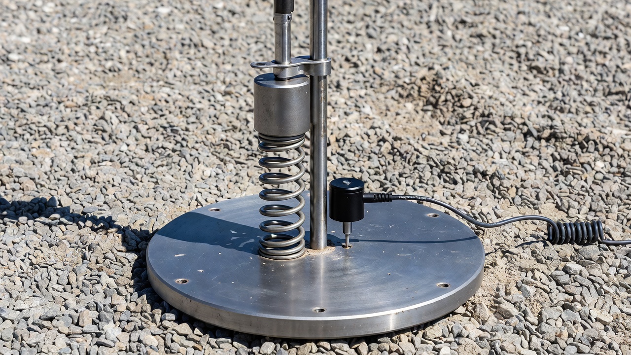
The operating principle of the Light Weight Deflectometer is based on dynamic plate loading — applying a controlled impulse load to a circular plate resting on the ground surface and measuring the resulting vertical deflection. The device consists of six primary components: a guide rod with a fixed or adjustable height stop, a drop weight of known mass (typically 10 kg, 15 kg, or 20 kg depending on the manufacturer), a buffer system (rubber pads or steel springs) that shapes the load pulse, a circular loading plate (100 mm, 150 mm, 200 mm, or 300 mm diameter), a deflection transducer (geophone or accelerometer) that measures the surface response, and an electronic data acquisition unit that records force, deflection, and calculates the deformation modulus.
In operation, the loading plate is placed on the prepared surface of the compacted geomaterial. The operator lifts the drop weight along the guide rod to the preset drop height — typically 720 mm for the standard Zorn configuration, with adjustable heights available on other commercial devices — and releases it. The weight falls under gravity and strikes the buffer system, which compresses and transfers the kinetic energy to the loading plate as a shaped force pulse. The buffer system serves a critical function: it transforms the instantaneous impact into a controlled haversine-shaped load pulse with a duration of 15 to 30 milliseconds, approximating the loading rate of a moving vehicle tire. The peak force generated by the impact can be calculated from the theoretical relationship:
F = √(2 × m × g × h × c)
where F is the applied force (N), m is the mass of the falling weight (kg), g is the acceleration due to gravity (9.81 m/s²), h is the drop height (m), and c is the spring stiffness constant of the buffer (N/m). For a standard 10 kg weight dropped from 720 mm with steel spring buffers, the peak force is approximately 7.07 kN. This force, distributed over the loading plate area, produces a peak contact stress of 100 to 200 kPa — closely matching the stress level applied to the subgrade or base layer by a typical truck tire or aircraft landing gear wheel.
The deflection sensor — either a geophone (velocity transducer) in contact with the ground surface through a central annulus in the loading plate, or an accelerometer mounted directly on the loading plate — measures the vertical movement of the surface during the loading event. The geophone measures the velocity of the ground surface, and the onboard electronic processor integrates the velocity signal to determine peak deflection. An accelerometer measures acceleration directly, and the processor double-integrates the signal to derive deflection. Modern LWD systems from manufacturers such as Dynatest and Keros use geophones positioned on the ground surface through the center of an annulus plate, which ASTM E2583 identifies as the preferred configuration because it measures ground deflection directly without plate-soil interaction effects. Other systems, such as the Zorn LWD, use accelerometers mounted on the loading plate, which are simpler but may include plate deformation effects in the measurement.
The standard test sequence specified in ASTM E2583-07 consists of a minimum of three seating drops followed by a minimum of three recording drops at each test location. The seating drops condition the surface, ensuring full, intimate contact between the loading plate and the underlying material. Incomplete seating produces artificially high deflections and erroneously low modulus values. The recording drops are used to compute the average deflection and modulus for the test point. The coefficient of variation (CV) across the three recording drops should not exceed 5% for reliable results; higher CV values indicate material variability, inadequate surface preparation, or equipment malfunction requiring investigation.
Measured Parameters — Deflection and Modulus (E_LWD)
The Light Weight Deflectometer produces two primary measured or computed parameters: peak surface deflection (d) measured in millimeters or micrometers, and the dynamic deformation modulus (E_LWD) measured in megapascals (MPa). The peak deflection is the maximum vertical displacement of the ground surface at the center of the loading plate during the impulse load event. This value represents the material’s immediate elastic response to the applied stress and serves as the primary field measurement from which all subsequent parameters are derived.
The deformation modulus E_LWD is calculated from the measured deflection using Boussinesq’s elastic half-space theory, which describes the relationship between an applied load on a circular plate resting on a homogeneous, isotropic, linear elastic medium and the resulting surface deflection. The fundamental equation governing this relationship is:
E_LWD = (q × r × (1 − ν²) × f_r) / d
where E_LWD is the dynamic deformation modulus of the compacted geomaterial (MPa), q is the maximum contact pressure under the loading plate (MPa), calculated as q = F / A where F is the peak applied force (N) and A is the area of the loading plate (mm²), r is the radius of the loading plate (mm), ν is the Poisson’s ratio of the compacted geomaterial (typically assumed as 0.35 for granular materials and 0.45 for fine-grained soils), f_r is the plate rigidity factor (dimensionless, ranging from π/2 = 1.571 for a perfectly rigid plate to 2 for a perfectly flexible plate on an elastic material), and d is the measured peak deflection at the center of the loading plate (mm).
The plate rigidity factor (f_r) accounts for the stress distribution beneath the loading plate, which varies depending on whether the plate behaves as a rigid or flexible element and on the type of material being tested. For a perfectly rigid plate on a cohesive elastic material (clay), the contact stress distribution is parabolic — minimum at the center and maximum at the edges — yielding f_r = π/2 ≈ 1.571. For a flexible plate on clay, the stress distribution is uniform, yielding f_r = 2. For cohesionless granular materials (sand, crushed aggregate), the stress distribution is inverse parabolic for both rigid and flexible plates, yielding f_r = π/2 = 1.571. For materials with mixed properties (the typical case for compacted subgrade and base materials), f_r ranges between 1.571 and 2.0, and the analyst must select an appropriate intermediate value based on engineering judgment or use the relative plate rigidity parameter K calculated from:
where E_p and E_s are the elastic moduli of the plate and soil, ν_p and ν_s are Poisson’s ratios of the plate and soil, and t_p is the thickness of the loading plate. For K = 0, the plate behaves as perfectly flexible; for K → ∞, the plate behaves as perfectly rigid.
The depth of influence of the LWD test is approximately 1.0 to 1.5 times the diameter of the loading plate. A 300 mm diameter plate therefore evaluates the material to a depth of approximately 300 to 450 mm (12 to 18 inches) below the surface, which is sufficient to assess a single compacted lift of subgrade or base course material (typically 150 to 200 mm compacted thickness). A 100 mm diameter plate evaluates only the top 100 to 150 mm, making it suitable for thin lifts or surface quality assessment. This relationship between plate diameter and depth of influence is critical for proper test planning: the plate diameter must be selected so that the depth of influence encompasses the full thickness of the layer being evaluated without extending into underlying materials that would affect the measurement.
Commercial LWD devices vary in their specific configurations. The following table summarizes key specifications for the major LWD manufacturers:
Parameter
Zorn
Keros
Dynatest
Prima
Loadman
ELE
Plate type
Solid
Annulus
Annulus
Annulus
Solid
Solid
Plate diameter (mm)
100, 150, 200, 300
150, 200, 300
100, 150, 200, 300
100, 200, 300
110, 130, 200, 300
300
Drop mass (kg)
10, 15
10, 15, 20
10, 15, 20
10, 15, 20
10
10
Drop height (mm)
720
Variable
Variable
Variable
800
Variable
Buffer type
Steel springs
Rubber (conical)
Rubber (flat)
Rubber (conical)
Rubber
Rubber
Sensor type
Accelerometer
Geophone
Geophone
Geophone
Accelerometer
Geophone
Sensor location
In plate
On ground
On ground
On ground
In plate
On ground
Max load (kN)
7.07
15.0*
15.0*
15.0*
20*
10*
Plate rigidity
Uniform
Rigid/flexible
Rigid/flexible
User defined
Rigid/flexible
User defined
*Maximum load varies based on drop height configuration.
LWD for Compaction Quality Control
The principal application of the Light Weight Deflectometer is compaction quality control (QC) — the verification that compacted geomaterials achieve the required stiffness and load-bearing capacity during construction. Compaction is the process of mechanically densifying soil or aggregate by reducing the air void volume between particles, increasing density, shear strength, and stiffness, and decreasing permeability and compressibility. The objective of compaction QC is to ensure that the constructed material meets the design assumptions used in pavement thickness design — specifically, that the material achieves the target resilient modulus (MR) or California Bearing Ratio (CBR) assumed in the structural design.
Traditional compaction QC has relied on density-based methods — the sand cone test (ASTM D1556) , the rubber balloon test (ASTM D2167) , and the nuclear density gauge (ASTM D6938) — which measure the in-place density and compare it to the laboratory maximum dry density determined by the Proctor compaction test (ASTM D698 or D1557) . The acceptance criterion is typically expressed as a percentage of maximum dry density — for example, 95% of Standard Proctor density for highway subgrade or 100% for FAA-specified airport base course. While density-based QC has been the industry standard for decades, it has well-recognized limitations. Density is an indirect measure of compaction quality: it tells how tightly particles are packed but does not directly measure how the material will perform under load. Materials can achieve high density but low stiffness if the particles are poorly graded, rounded rather than angular, or if the material is at a moisture content that reduces effective stress between particles.
The LWD addresses these limitations by measuring modulus directly — a fundamental engineering property that governs the material’s stress-strain behavior under traffic loading. When a pavement layer is loaded by a vehicle tire or aircraft landing gear, the critical design parameters are the stresses and strains that develop within and beneath the layer. For flexible pavements, the two critical criteria are the horizontal tensile strain at the bottom of the asphalt layer (controlling fatigue cracking) and the vertical compressive strain at the top of the subgrade (controlling permanent deformation or rutting). Both of these strains are calculated using the moduli of each pavement layer as primary inputs. A compaction QC program based on modulus — measured rapidly in the field with the LWD — directly verifies that the constructed material meets the modulus value assumed in the design, providing a far more performance-relevant acceptance criterion than density alone.
The field procedure for LWD compaction QC follows a standardized sequence. The test area is first prepared by removing loose material from the surface and ensuring a level, planar contact area for the loading plate. The loading plate diameter is selected based on the layer thickness and material type — 300 mm for subgrade and base course evaluation (depths of 300 to 450 mm), 200 mm for intermediate depths, and 100 mm for surface layers and thin lifts. The LWD is positioned, the plate is checked for full contact with the surface, and the drop weight is lifted to the preset height and released for the first seating drop. After three seating drops, three recording drops are performed, with the deflection and modulus recorded for each drop. The average modulus of the three recording drops is reported as the E_LWD value for that test location.
The number and spacing of test locations depend on the project specifications and the variability of the material being compacted. Typical QC programs specify one LWD test per 500 to 1,000 m² (600 to 1,200 square yards) of compacted area, with additional testing in areas of suspected non-uniformity, near structures, and at transition zones between cut and fill sections. For each test location, the mean E_LWD value is compared to the target modulus value established for the project. If the measured modulus meets or exceeds the target, the layer is accepted. If it falls below the target, the area is reworked (typically by scarifying, adjusting moisture content, and re-compacting) and retested.
Target modulus values for compaction QC are established through one of three methods: (1) correlation with laboratory tests — the target E_LWD is determined by testing compacted specimens of the project materials in the laboratory to establish the relationship between E_LWD and the design parameter (MR or CBR); (2) test strip correlation — a test strip of the material is compacted at varying densities and moisture contents, and LWD measurements are correlated with nuclear density gauge readings to establish the E_LWD value corresponding to the specified percentage of maximum dry density; or (3) performance-based criteria — the target E_LWD is established based on the modulus value assumed in the mechanistic-empirical pavement design, verified through layered elastic analysis to ensure pavement strains remain below allowable limits for the design traffic.
LWD for Subgrade and Base Acceptance
The adoption of LWD testing for subgrade and base course acceptance has grown substantially as transportation agencies shift from density-based to performance-based specification frameworks. In a performance-based specification, the contractor is responsible for achieving a specified level of engineering performance (stiffness, modulus, strength) rather than following prescriptive methods (specified roller type, number of passes, layer thickness). The LWD provides the field measurement tool that makes performance-based specifications practical, offering rapid, non-destructive modulus measurements at a density of testing that supports statistical acceptance plans.
Subgrade acceptance using LWD typically targets E_LWD values in the range of 35 to 60 MPa for fine-grained soils and 40 to 80 MPa for granular subgrade materials, depending on the design assumptions and traffic level. The subgrade is the foundation of the entire pavement structure, and its modulus directly controls the required thickness of the overlying pavement layers. A subgrade that achieves higher modulus than assumed in the design allows for potential thickness reduction (in design-build projects) or provides a safety margin for extended pavement life. A subgrade with lower modulus than assumed requires either recompaction to increase stiffness or an increase in pavement thickness to protect the weaker subgrade from overstressing.
The depth of influence consideration is particularly important for subgrade acceptance testing. The standard 300 mm loading plate evaluates the top 300 to 450 mm of the subgrade. If the subgrade has been compacted in multiple lifts (each 150 to 200 mm thick), the LWD measurement integrated across the top several lifts reflects the composite stiffness of the upper subgrade profile. If a weaker lift exists below 450 mm, the standard LWD test may not detect it. This limitation can be addressed by using larger loading plates (which increase depth of influence) or by performing supplementary testing with the Dynamic Cone Penetrometer (DCP) , which can evaluate subgrade strength to depths of 1,000 mm or more.
Base course acceptance using LWD targets higher modulus values than subgrade, reflecting the higher-quality materials and higher compaction standards specified for base layers. Typical target E_LWD values for unbound granular base course range from 80 to 120 MPa, depending on aggregate quality, gradation, and the specified level of compaction. For cement-treated or asphalt-treated base materials, target values are significantly higher — 120 to 200 MPa for cement-treated base and 100 to 180 MPa for asphalt-treated base. These higher targets reflect the stiffness contributed by the cementitious or bituminous binder, which provides beam strength that unbound granular materials cannot achieve.
The testing protocol for base course acceptance follows the same general procedure as subgrade testing but with some important differences. The surface of the base course must be clean and free of loose particles before placing the loading plate. Any loose material between the plate and the compacted surface will compress during the seating drops and produce erroneously low modulus readings. The plate contact must be verified by checking that the plate does not rock or tilt on the surface and that no gaps are visible between the plate edge and the material surface. For open-graded or very coarse base materials (maximum particle size up to 50 mm), the 300 mm loading plate may not achieve adequate contact, and a sand-cushioning layer or bedding sand may be required to fill surface voids and ensure uniform load distribution.
Several state highway agencies in the United States have developed specific LWD acceptance criteria for base course materials. The Maryland Department of Transportation (MDOT) conducted an extensive study under the Transportation Pooled Fund Program (TPF-5(285)) titled “Standardizing Lightweight Deflectometer Modulus Measurements for Compaction Quality Control,” which developed protocols for establishing target E_LWD values, correction factors for moisture content and plate diameter effects, and statistical acceptance plans based on lot testing. The Indiana Department of Transportation (INDOT) has incorporated LWD testing into its standard specifications for base course acceptance, requiring minimum E_LWD values verified through field testing. The Washington State Department of Transportation (WSDOT) developed correlations between LWD modulus and field density for common base course materials used in the Pacific Northwest.
LWD vs Falling Weight Deflectometer (FWD)
The Light Weight Deflectometer and the Falling Weight Deflectometer operate on the same fundamental principle — impulse loading and deflection measurement — but differ substantially in scale, application, and the information they provide. Understanding these differences is essential for selecting the appropriate device for a given testing objective.
The Falling Weight Deflectometer is a trailer-mounted or truck-mounted system weighing 1,000 to 3,000 kg (2,200 to 6,600 pounds). It applies impulse loads ranging from 4 kN to 150 kN (900 to 33,700 lbf) through a 300 mm diameter segmented loading plate. The FWD is equipped with 7 to 9 geophone sensors arranged at radial offsets from the load center — typically 0, 200, 300, 450, 600, 900, 1,200, 1,500, and 1,800 mm (0 to 72 inches). This multi-sensor array captures the full deflection basin — the three-dimensional bowl-shaped surface deformation created by the load impulse. The shape and magnitude of the deflection basin are functions of the stiffness and thickness of each pavement layer, enabling back-calculation of individual layer moduli (surface, base, subbase, subgrade) through iterative layered elastic analysis using software such as ELMOD, DARWin, or EVERCALC.
The Light Weight Deflectometer is a hand-portable device weighing 15 to 30 kg (33 to 66 pounds). It applies impulse loads of 5 to 20 kN (1,100 to 4,500 lbf) through solid or annulus loading plates of 100 to 300 mm diameter. The LWD typically uses a single deflection sensor at the center of the loading plate, measuring only the maximum deflection directly under the load. Some advanced LWD systems (such as Dynatest) offer an optional geophone kit with up to three sensors on a sensor beam, providing limited deflection basin information, but the standard LWD configuration provides a single deflection value and a single computed modulus — not sufficient information for multi-layer back-calculation.
The fundamental difference in application stems from the difference in information content. The FWD evaluates the complete pavement structure through an existing surface layer, providing layer-specific moduli for each pavement component. This makes it the appropriate tool for structural evaluation of in-service pavements, overlay design, remaining life assessment, and pavement management network-level surveys. The LWD evaluates the top layer only (to a depth of 1.0 to 1.5 times the plate diameter), making it the appropriate tool for layer-by-layer compaction QC during construction, where the objective is to verify that each newly compacted layer meets its target stiffness before the next layer is placed.
The stress levels applied by the two devices also differ. The FWD applies contact stresses of 200 to 700 kPa (29 to 102 psi) — sufficient to evaluate bound pavement layers (asphalt and concrete) and to generate measurable deflections through thick pavement structures. The LWD applies contact stresses of 100 to 200 kPa (14 to 29 psi) — matching the stress level applied to subgrade and base layers by typical traffic loads but insufficient to generate measurable deflections through thick bound pavement layers. This makes the LWD unsuitable for evaluating structural capacity of completed pavements with thick asphalt or concrete surfaces.
Despite these differences, the LWD and FWD produce modulus values that correlate well when testing the same materials. Research by the FHWA Long-Term Pavement Performance (LTPP) program, the Nebraska Department of Transportation, and numerous academic studies has documented correlation coefficients (R²) exceeding 0.80 between LWD and FWD modulus measurements on subgrade and base materials. The relationship is typically linear but material-specific: E_FWD = a × E_LWD + b, where coefficient a ranges from 0.8 to 1.2 and coefficient b is typically small but positive. These correlations enable agencies that have established FWD-based acceptance criteria to convert them to equivalent LWD targets, facilitating the adoption of LWD testing within existing specification frameworks.
Parameter
LWD
FWD
Portability
Hand-portable (15-30 kg)
Trailer/truck-mounted (1,000-3,000 kg)
Load range
5-20 kN
4-150 kN
Loading plate
100-300 mm (solid or annulus)
300 mm (segmented)
Sensors
1-3 (center only or beam)
7-9 (radial array up to 1,800 mm)
Depth of influence
1.0-1.5 × plate diameter
Full pavement structure
Output
Single modulus (E_LWD)
Layer moduli (back-calculated)
Primary application
Compaction QC, layer-by-layer
Structural evaluation, overlay design
Standards
ASTM E2583, E2835
ASTM D4694, D4695
Contact stress
100-200 kPa
200-700 kPa
Person operation
Single person
1-2 persons
LWD vs Nuclear Density Gauge (NDG)
The Nuclear Density Gauge (NDG) , governed by ASTM D6938, has been the dominant field compaction QC tool for decades, measuring in-place density and moisture content using radioactive isotopes — typically Cesium-137 (gamma source for density measurement) and Americium-241/Beryllium (neutron source for moisture measurement). The NDG emits gamma radiation that passes through the compacted material to detectors in the gauge base, and the attenuation of the radiation is proportional to the material density. The comparison between LWD and NDG is not a matter of which device is better but rather a question of what property should be measured for effective compaction QC.
The NDG measures density — the mass per unit volume of the compacted material, typically compared to the laboratory maximum dry density (MDD) determined by the Proctor test (ASTM D698 or D1557). Density-based QC accepts a compacted layer when the in-place dry density reaches a specified percentage of MDD — commonly 95% for subgrade, 98% for base, and 100% for airport pavements. Density is an indirect indicator of compaction quality: it measures how tightly the particles are packed together but does not directly measure how the material will perform under load.
The LWD measures stiffness or modulus — the material’s resistance to deformation under applied stress. Modulus is a direct engineering property that governs the material’s stress-strain behavior under traffic loading. A material with high modulus will deflect less under load, distribute stresses more effectively to underlying layers, and resist permanent deformation (rutting) better than a material with low modulus — even if both materials have the same density.
Research has consistently shown that the correlation between density and modulus is material-dependent and often weak. For some materials — particularly well-graded sands and gravels with angular particles — high density reliably produces high modulus. For other materials — particularly silty sands, clayey gravels, and materials compacted wet of optimum moisture content — high density may coexist with relatively low modulus. A material compacted at 95% of MDD at a moisture content 3% above optimum may achieve the required density but exhibit modulus values 30% to 50% lower than the same material compacted at optimum moisture. The density-based test passes the material; the modulus-based test correctly identifies its deficient structural performance.
The LWD offers several practical advantages over the NDG. Safety is the most significant — the NDG contains radioactive sources that require licensing from nuclear regulatory authorities, annual calibration, operator training and certification, radiation exposure monitoring, secure storage, and eventual disposal as radioactive waste. The LWD contains no radioactive materials, eliminating all regulatory, safety, and disposal concerns. Speed — the LWD requires 2 to 3 minutes per test point, including setup and recording; the NDG requires 1 to 4 minutes depending on the measurement mode (direct transmission or backscatter). Cost — the LWD typically costs $8,000 to $15,000 USD; the NDG costs $6,000 to $12,000 USD for the device but requires additional annual costs for licensing, calibration, operator training, and radiation safety programs that can add $2,000 to $5,000 per year. Operator independence — LWD results depend primarily on the material properties and plate contact condition, with minimal operator influence; NDG results can be affected by operator technique (source rod insertion depth, gauge placement, surface roughness) and by soil chemistry effects on the neutron moisture measurement.
The LWD is not, however, a complete replacement for the NDG. The NDG provides moisture content measurement, which the LWD does not. Moisture content is important for compaction control because materials compacted at moisture contents significantly above or below the optimum may achieve adequate modulus short-term but exhibit long-term performance problems — increased susceptibility to frost heave at high moisture, insufficient density for shear strength at low moisture. A comprehensive QC program may use both devices: the LWD for rapid, high-density modulus measurement across the entire compacted area, and the NDG or other moisture measurement device for periodic verification that moisture content remains within the specified range.
A study presented at the Transportation Association of Canada (TAC) 2019 Conference directly compared LWD and NDG for assessing compaction quality of base and subbase layers. The research found that LWD modulus measurements identified weak zones within accepted density areas — areas that met the 95% density requirement but exhibited modulus values below the project target. These zones, if not identified and corrected, would have produced premature rutting under traffic. The study concluded that LWD testing provides a valuable supplement to density testing, identifying performance-relevant deficiencies that density testing misses.
Parameter
LWD
NDG
Measured property
Modulus (E_LWD, MPa)
Density (kg/m³) and moisture (%)
Engineering relevance
Direct (stress-strain behavior)
Indirect (packing density)
Regulatory requirements
None
Nuclear license, training, security
Radiation hazard
None
Gamma and neutron radiation
Field testing time
2-3 minutes per point
1-4 minutes per point
Operator training
Minimal (1 day)
Extensive (certification required)
Calibration
Annual (simple)
Annual (must be certified)
Depth of measurement
~450 mm (300 mm plate)
Up to 300 mm (direct transmission)
Moisture measurement
No
Yes
Grid testing density
Practical (rapid, safe)
Less practical (slower, regulatory)
Temperature sensitivity
Buffer-dependent
Minimal
LWD Standards — ASTM E2583 and ASTM E2835
Two primary ASTM International standards govern the use of the Light Weight Deflectometer: ASTM E2583-07 (Reapproved 2020) — Standard Test Method for Measuring Deflections with a Light Weight Deflectometer (LWD), and ASTM E2835-11 (Reapproved 2021) — Standard Test Method for Measuring Deflections using a Portable Deflectometer (Light Weight Deflectometer). These standards establish the equipment specifications, testing procedures, data analysis protocols, and reporting requirements that ensure consistent, reproducible LWD measurements across different devices, operators, and project sites.
ASTM E2583 addresses the physical measurement of surface deflection under LWD loading. The standard specifies that the LWD must include a loading plate with a minimum diameter of 100 mm and a maximum diameter of 300 mm, a drop weight capable of producing a peak force between 3.8 kN and 20 kN, a buffer system that produces a load pulse duration between 15 and 30 milliseconds, and a deflection measurement system (geophone or accelerometer) with a resolution of at least 1 micrometer and an accuracy of ±2% of the reading or ±2 micrometers, whichever is greater. The standard requires that deflection be measured at the center of the loading plate, with the sensor either in direct contact with the ground surface through a central hole in an annulus plate (geophone) or mounted on the plate surface (accelerometer).
The testing procedure specified in ASTM E2583 requires: (1) preparing a level test surface free of loose material; (2) positioning the loading plate in full contact with the surface; (3) performing a minimum of three seating drops to ensure proper contact and condition the material; (4) performing a minimum of three recording drops at the same drop height; (5) recording the peak deflection for each recording drop; and (6) reporting the average deflection of the recording drops. The standard requires that the variation between recording drops not exceed 10% of the mean deflection; if it does, the test must be repeated after checking surface contact and equipment function.
ASTM E2835 addresses the calculation of the dynamic deformation modulus (E_LWD) from the deflection and force measurements obtained under ASTM E2583. The standard specifies the use of Boussinesq’s elastic half-space equation for a rigid circular plate on a homogeneous, isotropic, linear elastic medium. The standard requires that the following parameters be recorded and reported for each test: peak applied force (F, in kN), loading plate diameter (D, in mm), peak deflection (d, in mm or micrometers), Poisson’s ratio of the tested material (assumed or measured), and the plate rigidity factor (f_r). The standard provides guidance on selecting appropriate values for Poisson’s ratio (0.35 for granular materials, 0.45 for fine-grained soils) and the plate rigidity factor (π/2 = 1.571 for rigid plate conditions, 2.0 for flexible plate conditions).
Both standards emphasize calibration as essential for data quality. ASTM E2583 requires that the deflection sensor be calibrated annually against a traceable reference standard and that the load cell (if equipped) be calibrated annually. ASTM E2835 requires that the computed modulus be verified against known reference values at least annually, typically by testing on a rigid laboratory floor or a reference material of known modulus. The standards also require that the drop height be calibrated and that the buffer system be inspected regularly for wear, cracking, or deformation that could affect load pulse characteristics.
In addition to the ASTM standards, many transportation agencies have developed supplemental agency-specific protocols that adapt the ASTM procedures to local conditions and specifications. These agency protocols typically specify: the loading plate diameter to be used for each material type; the number and spacing of test locations; the target E_LWD values for acceptance; the statistical sampling and acceptance plan; the procedures for establishing target values through test strips or laboratory correlation; and the corrective actions required when measured modulus falls below the target value.
International standards also address LWD testing. The British Standard BS 1924-2 specifies LWD testing for stabilized materials. The German Standard DIN 18134 (Plate Loading Test) addresses plate loading testing conceptually related to LWD principles but using static rather than dynamic loading. The Swiss Standard SN 670 325b provides guidelines for LWD testing in earthworks and foundation engineering. The growing international adoption of LWD testing reflects its recognized value for efficient, performance-relevant compaction QC across diverse construction environments.
Airport Construction Applications
The Light Weight Deflectometer has particular relevance for airport pavement construction due to the stringent quality requirements and the direct relationship between subgrade/base stiffness and pavement thickness for aircraft loads. Airport pavement design per FAA Advisory Circular AC 150/5320-6G uses layered elastic analysis in the FAARFIELD software, which requires each pavement layer to achieve a specified modulus for the design to be valid. The LWD provides the field verification tool to confirm that as-constructed layer moduli meet or exceed the design assumptions.
The Federal Aviation Administration (FAA) has conducted extensive research on LWD applications for airfield pavements through multiple programs. The Airport Cooperative Research Program (ACRP) has published reports on the use of LWD for quality assurance of compacted layers during airport pavement construction. The FAA National Airport Pavement Test Facility (NAPTF) in Atlantic City, New Jersey, has conducted full-scale accelerated pavement testing to develop correlations between LWD modulus and pavement performance under simulated aircraft loading. The FAA Airport Technology Research and Development Branch has published guidance documents on LWD testing procedures, data interpretation, and acceptance criteria specifically for airport applications.
The ICAO Aerodrome Design Manual Part 3 — Pavements (Doc 9157) provides international guidance on pavement evaluation and quality control. While ICAO does not prescribe specific LWD testing protocols, the manual recognizes the value of modulus-based testing for compaction QC and references the use of deflectometer devices as part of a comprehensive pavement quality assurance program. For international airport projects, LWD testing is typically conducted in accordance with ASTM standards supplemented by project-specific technical specifications that establish target modulus values based on the FAA FAARFIELD design assumptions.
Construction quality control for airport pavement layers using LWD follows a structured protocol. The subgrade must achieve a target modulus that corresponds to the design California Bearing Ratio (CBR) assumed in the pavement thickness analysis. For a typical commercial service airport subgrade designed at CBR 6 (characteristic of medium-strength subgrade), the target E_LWD typically ranges from 40 to 60 MPa. For the base course, specified per FAA Item P-209 (Crushed Aggregate Base Course) for heavy aircraft loads, the target E_LWD typically ranges from 80 to 120 MPa. For cement-treated base (FAA Item P-210 ), the target E_LWD ranges from 120 to 200 MPa, with the specific target depending on the cement content and the 7-day compressive strength specification.
The correlation between LWD modulus and CBR is particularly important for airport applications, as the FAA design procedure traditionally uses CBR as the primary subgrade strength parameter. Research has developed empirical correlations such as:
These correlations enable airport engineers to convert LWD modulus measurements into equivalent CBR values for comparison with design assumptions. However, the correlations are material-specific and should be verified through laboratory testing on the actual project materials for critical applications.
The FAA Advisory Circular 150/5370-10H — Standard Specifications for Construction of Airports — provides the material specifications and construction standards for airport pavement layers. While the AC references traditional density-based compaction control as the primary acceptance method, it recognizes that stiffness and modulus testing provides supplemental quality information. Many airport projects now incorporate LWD testing as a quality control tool even when density-based acceptance is used for formal acceptance, providing the contractor and engineer with real-time feedback on compaction effectiveness and identifying areas requiring additional effort before formal acceptance testing.
Airport pavement quality assurance (QA) programs increasingly use LWD testing for independent assurance — the verification by the owner’s representative that the contractor’s QC program is producing consistent, acceptable results. The portability and rapid testing speed of the LWD enable the QA team to conduct independent tests at a higher frequency than would be practical with nuclear density gauges, providing greater confidence in the uniformity and quality of compaction across large pavement areas typical of airport construction (runway pavement areas of 50,000 to 200,000 m² are common).
Interpretation and Quality Control
Proper interpretation of LWD data requires understanding the factors that affect modulus measurements and the statistical framework for acceptance decisions. The interpretation process begins with data screening to identify and exclude anomalous test results caused by poor plate contact, surface disturbance, or equipment malfunction. The coefficient of variation (CV) across the three recording drops at each test point should not exceed 5% for reliable data, and the difference between the seating drop modulus and the recording drop modulus should be less than 10% for stable test conditions.
Spatial variability is an inherent characteristic of compacted geomaterials, and LWD modulus values will naturally vary across even a well-constructed pavement layer. The coefficient of variation (CV) across test points within a uniform construction lot typically ranges from 10% to 25% for subgrade materials and 8% to 20% for base course materials. Higher CV values indicate non-uniform compaction, material variability, moisture variation, or inadequate quality control. The acceptance plan must account for this variability through appropriate statistical sampling and decision rules.
Statistical acceptance plans for LWD testing typically follow one of three approaches. The average value approach — the simplest — specifies a minimum average E_LWD value for a lot, with individual test points allowed to fall below the target as long as the lot average meets the requirement. This approach is appropriate for projects where some variability is acceptable and the primary concern is overall structural adequacy. The percent within limits (PWL) approach — used in many state highway agency specifications — specifies that a minimum percentage of test values must exceed a specified threshold. For example, the specification might require 90% of tested points to exceed 80 MPa, with the remaining 10% allowed to fall between 60 and 80 MPa but not below 60 MPa. The individual minimum value approach — the most stringent — specifies a minimum E_LWD value that every test point must meet with no exceptions. This approach is used for critical applications where any weak zone could cause premature failure, such as airport runway pavements.
Moisture content effects on LWD modulus are significant and must be accounted for in data interpretation. The modulus of compacted geomaterials varies with moisture content in a characteristic pattern: modulus increases as moisture content decreases from optimum, and decreases as moisture content increases above optimum. A material compacted at 95% MDD but at a moisture content 3% above optimum may exhibit E_LWD values 40% to 60% lower than the same material compacted at optimum moisture. If LWD testing identifies unexpectedly low modulus values, the first diagnostic step should be to check moisture content — if the material is wet of optimum, the corrective action is to aerate and dry the material before recompaction, not to simply re-roll without addressing the moisture issue.
Temperature effects on the LWD device itself must also be considered, particularly when using rubber buffers. Research has shown that rubber buffer stiffness varies with temperature — a change from 0°C to 30°C can reduce rubber stiffness by approximately 30%, decreasing the applied force and potentially affecting the measured modulus. Steel spring buffers are not affected by temperature and are recommended for consistent results, particularly when testing in cold weather or across wide temperature ranges.
Recommended practice for LWD quality control includes the following elements: (1) establish project-specific target E_LWD values through correlation testing on project materials before production compaction begins; (2) conduct LWD testing at a frequency that provides statistically representative coverage — typically one test per 500 to 1,000 m² for subgrade and one test per 250 to 500 m² for base course; (3) use the 300 mm loading plate as the standard configuration for subgrade and base testing, reserving smaller plates for thin lifts and specialty applications; (4) always perform the minimum of three seating drops and three recording drops specified by ASTM E2583; (5) verify plate contact visually and through monitoring of drop-to-drop variability before accepting test results; (6) record moisture content at each test location or at a subset of locations to identify moisture-related modulus variation; (7) apply statistical acceptance criteria appropriate to the project criticality and risk tolerance; and (8) investigate outlier test results immediately — low modulus values not explained by moisture or material variation may indicate inadequate compaction effort requiring rework.
The Light Weight Deflectometer has established itself as an essential tool for modern construction quality control, providing rapid, non-destructive modulus measurements that directly verify the structural performance of compacted geomaterials. Its portability, safety advantages over nuclear gauges, and performance-relevant output make it particularly valuable for projects where compaction quality is critical to long-term pavement performance — including highway, airport, and heavy industrial pavements subject to high traffic loads and demanding performance requirements.
Frequently Asked Questions
A Light Weight Deflectometer is a portable non-destructive testing device used for on-site evaluation of soil and aggregate compaction quality. It consists of a guide rod, a drop weight (typically 10 kg or 15 kg), buffer springs or rubber pads, a circular loading plate (100-300 mm diameter), and a deflection sensor (geophone or accelerometer). The device is placed on the surface to be tested, the weight is lifted to a preset drop height, and released to strike the buffer system, generating an impulse load of 5 to 20 kN on the loading plate. The resulting surface deflection is measured at the center of the plate, and the dynamic deformation modulus (ELWD) is calculated using Boussinesq's elastic half-space theory. The test is conducted in accordance with ASTM E2583 for deflection measurement and ASTM E2835 for modulus calculation.
The LWD works by applying a controlled impulse load to the ground surface and measuring the resulting deflection. A weight of known mass (typically 10 kg) is dropped from a preset height (typically 720 mm) onto a buffer system (steel springs or rubber pads) that sits atop a circular loading plate. The impact generates a force pulse of 15-30 milliseconds duration, producing a peak load of approximately 7.07 kN for the standard configuration. A geophone or accelerometer measures the vertical deflection of the plate or the ground surface at the center of the loading plate. The device outputs two primary parameters: peak surface deflection (in mm or mils) and the dynamic deformation modulus (ELWD), calculated as ELWD = (q × r × (1-ν²) × f) / w, where q is contact pressure, r is plate radius, ν is Poisson's ratio, f is the plate rigidity factor, and w is the measured deflection.
The LWD and FWD operate on the same fundamental principle — dropping a weight onto a loading plate and measuring deflections — but differ significantly in scale and application. The FWD is a trailer-mounted or truck-mounted device applying loads of 4 to 150 kN with 7 to 9 geophone sensors arranged at radial distances up to 1,800 mm, used for structural evaluation of complete pavement systems. The LWD is a hand-portable device applying loads of 5 to 20 kN with a single center sensor (or up to 3 sensors), used for evaluating individual pavement layers during construction. The FWD measures deflection basins for multi-layer back-calculation; the LWD provides a single modulus value for the top 1.0 to 1.5 times the plate diameter. The LWD is designed for compaction QC during construction; the FWD is designed for structural evaluation of completed pavements. Despite these differences, studies show strong correlation (R² > 0.80) between LWD and FWD modulus measurements on the same materials.
The LWD and Nuclear Density Gauge measure fundamentally different properties. The NDG measures the physical density and moisture content of compacted materials using gamma radiation and neutron moderation. The LWD measures the mechanical stiffness (modulus) of compacted materials under dynamic loading. Density is an indirect indicator of compaction quality — it measures how tightly particles are packed. Modulus is a direct engineering property that governs how the material will perform under load — how much it will deflect and whether it will rut or fail. Research has shown that density-based acceptance criteria (e.g., 95% of maximum dry density) do not always correlate well with stiffness or performance, particularly for granular materials where particle interlock and gradation affect stiffness independently of density. The LWD offers advantages over NDG: no radioactive material (eliminating licensing, safety, and disposal costs), faster testing (2-3 minutes per test point), single-person operation, and direct performance-related output (modulus rather than density).
Two primary ASTM standards govern LWD testing: ASTM E2583-07 (Reapproved 2020) — Standard Test Method for Measuring Deflections with a Light Weight Deflectometer (LWD). This standard specifies the equipment configuration, test procedure, seating drops (3 minimum), recording drops (3 minimum), and data reporting requirements for deflection measurement. It requires measuring deflection at the center of the loading plate using either a geophone in contact with the ground through an annulus in the plate, or an accelerometer mounted on the plate. ASTM E2835-11 (Reapproved 2021) — Standard Test Method for Measuring Deflections using a Portable Deflectometer (Light Weight Deflectometer). This standard covers the calculation of the dynamic modulus (ELWD) from measured force and deflection data, specifying the use of Boussinesq's equation for a rigid or flexible plate on an elastic half-space. Additional test method standards that apply to LWD use include ASTM D4695 (General Pavement Deflection Measurements) for survey planning and ASTM D5858 (Calculating In Situ Equivalent Elastic Moduli) for modulus interpretation.
The LWD is used in airport construction for quality control of compacted subgrade and base course layers. The FAA has conducted extensive research through the Airport Cooperative Research Program (ACRP) and the National Airfield Pavement Test Facility to evaluate LWD for airfield pavement acceptance testing. FAA Advisory Circular AC 150/5370-10H references LWD testing as an acceptable method for compaction quality control. For airport applications, the LWD is particularly valuable because it provides immediate modulus data that can be correlated with the California Bearing Ratio (CBR) and resilient modulus (MR) values used in FAA FAARFIELD pavement design software. Typical target ELWD values for airport subgrade range from 35 to 60 MPa, while base course targets range from 80 to 120 MPa for granular materials and up to 170 MPa for stabilized materials. The LWD can also be used to monitor strength gain in stabilized base courses over time, verify uniformity of compaction across large pavement areas, and identify weak zones requiring rework before the surface course is placed.
Several factors influence LWD modulus (ELWD) measurements and must be controlled for consistent results: (1) Loading plate diameter — smaller plates (100 mm) produce higher contact stresses and higher modulus values than larger plates (300 mm). A change from 300 mm to 100 mm diameter can increase ELWD by 1.5 to 1.6 times. (2) Plate rigidity — rigid plates produce different stress distributions under the plate than flexible plates, requiring different plate rigidity factors (fr ranging from 0.157 to 2.67). (3) Buffer type — steel springs provide consistent force output regardless of temperature; rubber buffers soften when heated, causing force variations of up to 30% over a 0 to 30°C temperature range. (4) Plate contact stress — higher contact stress generally produces higher ELWD values for granular materials but not for soft subgrade soils. (5) Drop height — increasing drop height increases applied force and can affect measured modulus. (6) Material type — cohesive soils typically show less modulus variation with test conditions than granular materials. (7) Moisture content — saturated or very dry conditions significantly reduce modulus values. (8) Seating condition — incomplete contact between the plate and the ground surface produces erroneously high deflection and low modulus readings.
Based on extensive field-testing data compiled from multiple studies in the literature, typical ELWD values for various construction geomaterials fall within the following ranges: Fine-grained soils (silts and clays) — 15 to 40 MPa depending on moisture content and compaction level; sandy soils — 25 to 50 MPa; well-graded sand-gravel mixtures — 35 to 60 MPa; crushed aggregate base course — 80 to 120 MPa; cement-treated base — 120 to 200 MPa; asphalt-treated base — 100 to 180 MPa; thin asphalt pavements (< 50 mm) — 120 to 170 MPa; and stabilized subgrade with cement or lime — 50 to 100 MPa. These ranges serve as general guidelines only, as site-specific target values should be established through correlation testing with laboratory resilient modulus (MR) or CBR tests on the actual project materials. Many transportation agencies have developed their own ELWD acceptance criteria through calibration studies.
Optimize Your Construction Quality Control Program
Integrating Light Weight Deflectometer testing into your construction QC program provides direct stiffness and modulus data that complements visual inspection and density testing. Our pavement evaluation specialists can help you develop LWD-based acceptance criteria, establish modulus targets for your materials, and train your field staff on standardized testing protocols per ASTM E2583.
The Falling Weight Deflectometer (FWD) is a non-destructive pavement testing device that drops a known impulse load onto a loading plate, measuring surface defl...
FWD deflection data analysis processes the measured deflection basin from FWD testing to back-calculate the elastic modulus of each pavement layer (HMA, base, s...
Nuclear Density Gauge for Soil and Asphalt Density
The nuclear density gauge is a field instrument that uses gamma radiation and neutron thermalization to measure in-place density and moisture content of soil, a...
32 min read
Geotechnical testing
Pavement quality control
+3
Cookie Consent We use cookies to enhance your browsing experience and analyze our traffic. See our privacy policy.