Load transfer devices (dowel bars, tie bars, aggregate interlock, keyed joints) transfer wheel loads across joints and cracks in concrete pavements, preventing differential deflection (faulting). Load Transfer Efficiency (LTE) is measured by FWD or deflectometer. Covers device types, LTE measurement, and inspection for load transfer deterioration.
Load Transfer Devices in Concrete Pavements: Complete Technical Reference
Function of Load Transfer Devices
A load transfer device is a structural component installed at or formed within a joint or crack in a Portland cement concrete (PCC) pavement that transfers a portion of an applied wheel load from one slab to the adjacent slab through shear action. When a wheel load approaches a transverse joint, the loaded slab deflects downward. Without a load transfer mechanism, the unloaded slab does not share this deflection, creating a differential vertical displacement (a step) at the joint — a condition known as faulting. The fundamental purpose of any load transfer device is to minimize this differential movement by transmitting vertical shear forces across the joint interface.
The physics of the mechanism operates as follows. As the wheel approaches the joint, the loaded slab bends under the applied load. The load transfer device — whether a dowel bar, aggregate interlock, or keyway — transmits a portion of the vertical shear force to the adjacent unloaded slab. The unloaded slab deflects partially in response, sharing the load and reducing the differential deflection. This load sharing reduces tensile stresses in the loaded slab, preventing corner breaks, and reduces pumping of subbase fines. The FHWA Guide for Load Transfer Restoration identifies three key effects of good load transfer: reduced tensile stresses in concrete (reducing potential for cracking and corner breaks), reduced corner deflections (reducing pumping and faulting development), and reduced differential deflections (reducing reflection crack deterioration in overlays).
The consequences of poor load transfer are severe and progressive. Faulting — a vertical step between adjacent slabs — develops within 5–10 years in undoweled pavements under heavy traffic. Every vehicle crossing the joint produces an impact loading that accelerates slab edge fatigue. Pumping of fines from beneath the slab edge creates voids, leading to loss of support. Corner breaks and mid-panel cracking develop as the structural capacity of the edge-loaded slab is exceeded. In airport pavements, faulting of even 2.5 mm (0.1 in) produces objectionable ride quality for aircraft and can accelerate foreign object debris (FOD) generation from spalled joint edges.
The shear transfer mechanism at a joint depends on the type of device. For dowel bars, shear force is transmitted through the dowel acting in double shear across the joint plane, with bearing stresses developed between the dowel and the surrounding concrete. For aggregate interlock, shear is transmitted by the interlocking of irregular aggregate particles on the fractured crack faces. For keyed joints, the interlocking slab geometry provides direct mechanical shear transfer. For all mechanisms, the stiffness of the load transfer system — characterized by the joint shear stiffness parameter — determines the proportion of load shared between slabs.
Dowel Bars
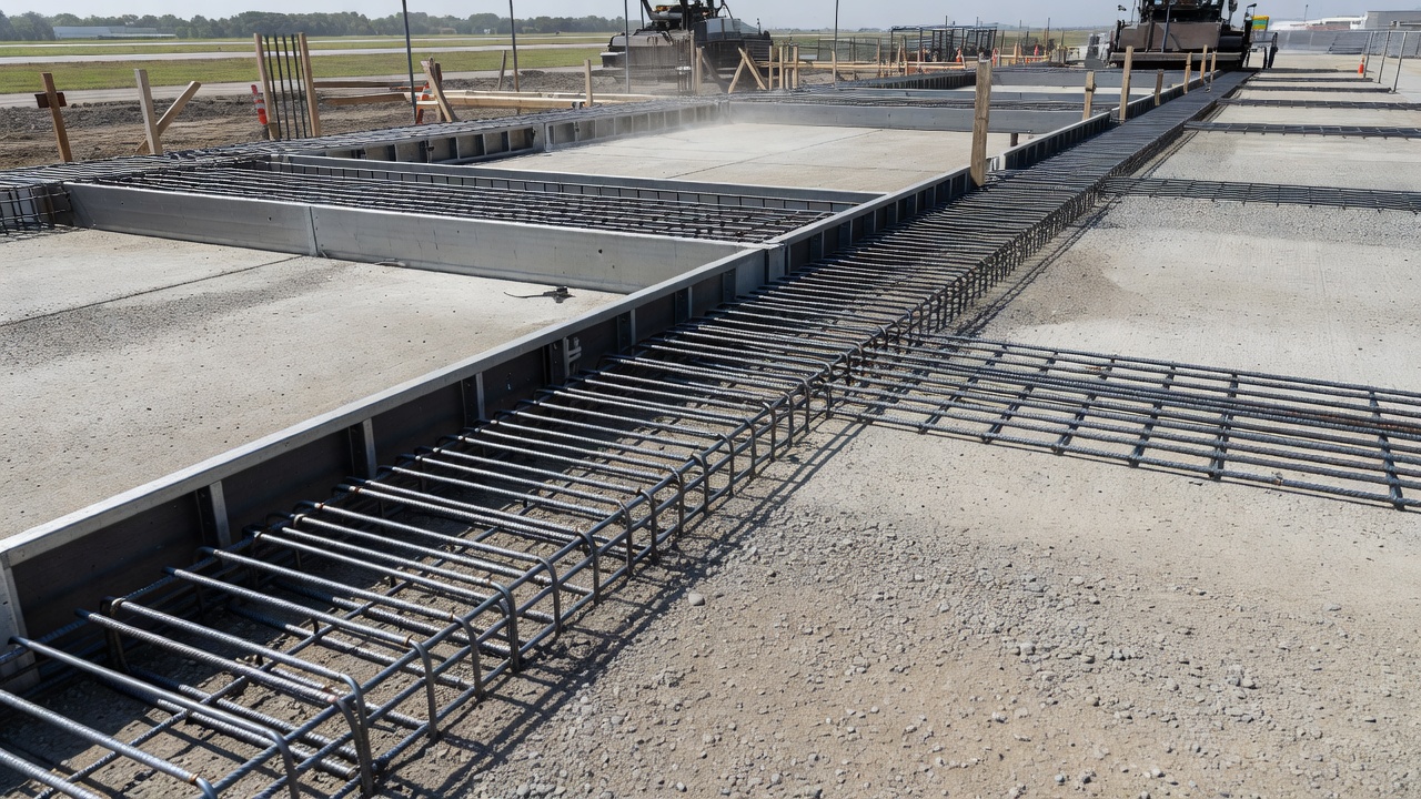
Dowel bars are the most common and effective load transfer device for transverse joints in concrete pavement. They are smooth, plain round steel bars installed horizontally across transverse contraction joints and construction joints. One half of each bar is embedded in one slab, and the other half extends into the adjacent slab. The smooth surface, combined with a bond breaker applied to one half, allows horizontal joint movement (opening and closing with thermal expansion and contraction cycles) while preventing relative vertical displacement. This differential movement capability — horizontal freedom combined with vertical restraint — is the defining characteristic that distinguishes dowel bars from all other load transfer devices.
Material Standards
Dowel bars must conform to rigorous material standards that govern steel grade, coating requirements, and dimensional tolerances. The primary standards applicable to dowel bar specification include ASTM A1078/A1078M (epoxy-coated steel dowels for concrete pavement), ASTM A615 Grade 60 (plain carbon steel base material, smooth hot-rolled bars), AASHTO M254 (corrosion-resistant coated dowel bars for US DOT projects), and ACPA M254-23 (comprehensive specification covering Type A, B, C, and D dowel categories). For corrosion-resistant applications, ASTM A775 and ASTM A934 govern fusion-bonded epoxy coating, ASTM A1094 covers hot-dip galvanized dowels, ASTM A955 (304, 316, and 316LN grades) covers stainless steel dowels, and ASTM D7957 covers fiber-reinforced polymer (FRP/GFRP) dowels. European applications follow EN 13877-3 for load transfer at concrete pavement joints.
Coating Type
Relative Cost
Service Life (Chloride Env.)
Standard
Fusion-Bonded Epoxy (FBE)
1.0× baseline
30–40 years
ASTM A1078, A775
Hot-Dip Galvanized
1.2×
15–25 years
ASTM A1094
Stainless Steel 316
4–5×
75–100 years
ASTM A955
FRP / GFRP
2.5–3×
100+ years (corrosion immune)
ASTM D7957
Dimensions by Slab Thickness
Dowel bar diameter, length, and spacing are functions of slab thickness. The general rule established by the AASHO Road Test and validated by decades of field performance is that dowel diameter (D) equals slab thickness (T) divided by 8. FAA AC 150/5320-6G, Table 3-6 provides the authoritative dimensions for airfield pavement dowels.
Slab Thickness
Dowel Diameter
Dowel Length
Spacing
5–7 in (125–178 mm)
3/4 in (20 mm)
18 in (460 mm)
12 in (305 mm)
7.5–12 in (191–305 mm)
1 in (25 mm)
18 in (460 mm)
12 in (305 mm)
12.5–16 in (318–406 mm)
1-1/4 in (30 mm)
20 in (510 mm)
15 in (380 mm)
16.5–20 in (419–508 mm)
1-1/2 in (40 mm)
20 in (510 mm)
18 in (460 mm)
20.5–24 in (521–610 mm)
2 in (50 mm)
24 in (610 mm)
18 in (460 mm)
The edge distance requirement specifies that the outermost dowel must be minimum 150 mm (6 in) and maximum 450 mm (18 in) from the free edge of the pavement. For highway and industrial applications, common industry practice per ACPA and FHWA uses 25 mm diameter dowels at 300 mm spacing for 150 mm slabs, increasing to 38 mm diameter at 300 mm spacing for 250–400 mm slabs.
Alignment Requirements
Dowel bar alignment is critical to joint performance. Misaligned dowels can lock the joint, preventing thermal movement and causing pavement distress. Per the ACPA Dowel Bar Alignment and Location Guide Specification (November 2018), five types of misalignment are defined: horizontal skew (rotation in the horizontal plane), vertical tilt (rotation in the vertical plane), side shift (longitudinal translation along the joint direction), vertical translation (depth deviation from design position), and lateral translation (horizontal offset across the joint width).
The Composite Misalignment (CM) quantifies total angular misalignment as the root-sum-square of horizontal skew and vertical tilt: CM = √(Horizontal Skew² + Vertical Tilt²). The Joint Score (JS) quantifies the cumulative impact of all misaligned dowels in a single joint on the joint’s ability to open and close freely. Each dowel is assigned a weighting factor based on its CM value: CM ≤ 0.6 in (15 mm) receives weight 0 (no penalty), CM between 0.6–0.8 in receives weight 2, CM between 0.8–1.0 in receives weight 4, CM between 1.0–1.5 in receives weight 5, and CM exceeding 1.5 in receives weight 10. The Critical Joint Score (JS_critical) is calculated as JS_critical = C × 15 × (Joint Width in ft / 12), where C is an adjustment factor ranging from 0.6 to 1.5 depending on climate, panel length, and base type.
Shear Transfer Mechanism and Performance
When a wheel load deflects the loaded slab, the dowel bar embedded in both slabs is forced into bending. The bending bar transmits a vertical shear force from the loaded slab to the adjacent slab. Simultaneously, the dowel generates bearing stresses against the concrete on both sides of the joint. The adjacent slab deflects partially in response, sharing the load. Properly designed dowels achieve Load Transfer Efficiency of 85–95% at transverse joints, compared to less than 50% for undoweled joints relying only on aggregate interlock. Pavement service life is extended by a factor of 2–3× under equivalent traffic loading, and joint faulting is virtually eliminated for the design life.
FAA Requirements
Per FAA AC 150/5320-6G, dowels are required in the last three transverse contraction joints from a free edge of pavement. Dowels are required in ALL construction joints (both transverse and longitudinal) unless a thickened or reinforced edge is provided. On stabilized bases, FAA notes there is “little benefit to providing more than minimum of dowels in last three joints from a free edge.” These requirements apply to all airfield concrete pavements serving aircraft operations.
Tie Bars
Tie bars are deformed steel bars used across longitudinal joints in concrete pavement to hold slab faces in close contact. Unlike dowel bars, tie bars prevent joint opening — they do NOT allow horizontal movement. The deformed surface of tie bars bonds with the surrounding concrete, creating an axial restraint that prevents adjacent slabs from separating.
Key Distinction from Dowel Bars
The fundamental differences between dowel bars and tie bars relate to surface finish, primary function, joint movement capability, orientation, and load transfer mechanism. Dowel bars have a smooth surface, are oriented across transverse joints, allow horizontal joint movement through a bond breaker on one half, and transfer load through shear and bending. Tie bars have a deformed surface, are oriented across longitudinal joints, prevent horizontal movement through full bonding with concrete, and do NOT act as load transfer devices themselves — they keep the joint tight so that aggregate interlock can provide load transfer.
Property
Dowel Bars
Tie Bars
Surface finish
Smooth
Deformed
Primary function
Load transfer across joint
Hold joint closed
Joint movement
Allows horizontal movement
Prevents horizontal movement
Orientation
Transverse joints
Longitudinal joints
Bond breaker
Required on one half
Not used
Load transfer mechanism
Shear through bending
Aggregate interlock (by keeping joint tight)
Axial load carrying
No
Yes
FAA Specifications
Per FAA AC 150/5320-6G, Paragraph 3.16.10.1, tie bars must be deformed bars conforming to Item P-501 specifications. For panels 6 inches or less in thickness, No. 4 bars (1/2 inch diameter) are used, 20 inches (510 mm) long, spaced at 36 inches (900 mm) on center. For panels exceeding 6 inches in thickness, No. 5 bars (5/8 inch diameter) are used, 30 inches (762 mm) long, spaced at 30 inches (762 mm) on center. FAA explicitly warns against using tie bars to create continuous tied joints greater than 75 feet (23 m) in length. Tie bars are required at longitudinal contraction joints within 20 feet (6 m) of a free edge for panels 9 inches or less in thickness.
FHWA Guidance
The FHWA Technical Advisory T 5040.30 specifies that tie bars are sized based on slab cross-sectional area, concrete density, coefficient of friction at the slab/subbase interface, and allowable steel stress (typically 27,000–36,000 psi for Grade 40–60 steel). The design equation ensures that the steel cross-section can resist the frictional force generated as the concrete contracts during temperature drops and drying shrinkage. Tie bars do not act as load transfer devices themselves — their function is exclusively to prevent joint opening so that aggregate interlock can provide effective load transfer across the longitudinal joint.
Aggregate Interlock
Aggregate interlock is the natural load transfer mechanism provided by the interlocking of rough, irregular aggregate particles exposed on the fractured face of a saw-cut and cracked joint. When a concrete pavement joint is constructed by saw-cutting a weakened plane, the controlled cracking that occurs below the saw cut produces irregular fracture surfaces. The aggregate particles on one crack face bear against those on the opposite face when a load is applied, transmitting shear forces through the joint.
The mechanism depends on the roughness of the fracture surface. In concrete with larger maximum aggregate size and stronger aggregate particles, the fracture path propagates around the aggregate (debonding at the aggregate-paste interface), creating a rough surface with aggregate particles protruding from the paste matrix. In concrete with weaker aggregate or very high strength paste, the fracture may propagate through the aggregate itself, creating a smoother surface with less interlock potential. The key parameter controlling aggregate interlock effectiveness is the joint opening width — experimental studies documented by FHWA HIPERPAV II show that a joint opening of 0.6 mm (0.024 in) or greater can translate to total loss of load transfer by aggregate interlock.
Degradation Factors
Aggregate interlock degrades over time through multiple interacting mechanisms. Traffic loading produces repeated load cycles that cause micro-crushing of aggregate at contact points, progressively wearing down the interlock surfaces. Thermal cycles — daily and seasonal temperature changes — cause the joint to open and close, gradually widening the joint gap and reducing the contact area between aggregate particles. Moisture infiltration softens the subbase material, increases slab deflections under load, and accelerates the wear of interlock surfaces. Freeze-thaw cycles during spring thaw conditions create saturated subbase conditions that accelerate pumping and erosion. Erodible subbase materials — particularly fine-grained soils — erode under repeated loading, creating voids that increase slab deflections and joint openings.
Applications and Limitations
Aggregate interlock is used primarily in low-volume roads and light-duty pavements where traffic loads are moderate and joint spacing is short enough to keep joint openings below the critical 0.6 mm threshold. For airfield pavements, FAA allows Type D (Dummy) contraction joints (without dowels) and Type B (Hinged) contraction joints for panels less than 9 inches (230 mm) thick. In these applications, aggregate interlock is only effective when joints remain tight, requiring short joint spacing (12.5–15 ft) to minimize thermal movement at each joint.
Keyed Joints
A keyed joint (also called a keyway joint) is a structural joint where one slab has a protruding “key” that fits into a matching groove in the adjacent slab, providing mechanical load transfer through interlocking geometry. The key is typically formed using a prefabricated U-shaped galvanized steel or metal form placed before concrete pouring. Common cross-sectional shapes include trapezoidal, rectangular, and dovetail configurations.
Keyed joints are used in applications with thicker slabs (≥ 250–300 mm / 10–12 in) where construction challenges of thinner keyways are less severe. They are most commonly applied at longitudinal construction joints between paving lanes and for load transfer between adjacent concrete sections where dowel bars are less practical. Keyed joints can be used in conjunction with dowels for additional support.
However, FAA AC 150/5320-6G does not include keyed joints as a standard joint type in Table 3-5. FAA standard joints are Types A through F (thickened edge, hinged, doweled, dummy, doweled construction, and butt construction). Keyed joints are generally not recommended for airfield pavements serving aircraft exceeding 30,000 lbs. Documented problems include cracking and damage due to inability to accommodate shrinkage and temperature changes, joint faulting creating height differences between slabs, potential misalignment during construction, and limited durability compared to properly doweled joints.
Load Transfer Efficiency (LTE) Definition and Measurement
Load Transfer Efficiency (LTE) is the quantitative measure of a joint’s ability to transfer load from a loaded slab to an adjacent unloaded slab. LTE is expressed as a percentage, where 0% indicates no load transfer (free edge condition) and 100% indicates perfect transfer (equal deflections on both sides of the joint). LTE is the single most important parameter for evaluating the condition of existing concrete pavement joints and determining the need for load transfer restoration.
Formulas
The deflection-based LTE formula (most widely used, per FHWA-RD-02-088) is LTE = (du / dl) × 100%, where dl is the maximum deflection at the joint of the loaded slab and du is the corresponding deflection of the unloaded slab. An alternate deflection formula computes LTE* = [2du / (dl + du)] × 100%. The two deflection formulas are mathematically related: LTE = 2 / [1 + (1/LTE*)] and LTE* = 2 / [1 + (1/LTE)].
A stress-based LTE formulation also exists: LTE_σ = (σu / σl) × 100%, where σl and σu are the stresses on the loaded and unloaded sides respectively. Critically, there is no one-to-one relationship between deflection-based and stress-based LTE. Research documented in the FHWA Guide for Load Transfer Restoration demonstrates that a deflection LTE of 60% may correspond to a stress LTE of only approximately 22%. This means the stress reduction benefit from load transfer is much smaller than the deflection reduction would suggest.
Acceptable Values
Source
Threshold
Interpretation
FHWA LTR Guide
≤ 60% deflection LTE
Retrofit load transfer should be considered
FHWA LTR Guide
≥ 60% deflection LTE
Generally adequate for existing pavements
FHWA LTR Guide
≥ 75% deflection LTE
Good load transfer
FHWA LTR Guide
≥ 85–95%
Excellent (doweled joints)
FAA (general practice)
≥ 75%
Acceptable for airfields
LTPP database analysis
≥ 90%
Typical for new doweled joints
LTE by Falling Weight Deflectometer (FWD)
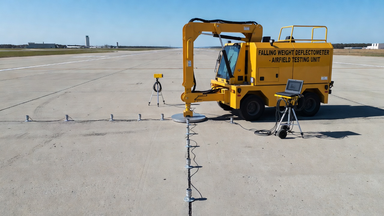
The Falling Weight Deflectometer (FWD) is the standard instrument for measuring load transfer efficiency in concrete pavements. Per ASTM D4694 (deflection measuring equipment) and ASTM D4695 (test method), the FWD system consists of a weight dropped from a specified height onto a load plate (producing an impulse force of typically 40–120 kN / 9,000–27,000 lbf), a load cell measuring the applied force, and 7–8 geophone sensors measuring pavement surface deflections at precise distances from the load plate center.
Sensor Configuration
Per FAA AC 150/5320-6G, Appendix C (Table C-2), the recommended sensor configuration for concrete pavement testing places Sensor 1 at the load plate center or edge, Sensor 2 at 12 inches (305 mm), Sensor 3 at 24 inches (610 mm), Sensor 4 at 36 inches (914 mm), Sensor 5 at 48 inches (1,219 mm), Sensor 6 at 60 inches (1,524 mm), and Sensor 7 at 72 inches (1,829 mm) from the load plate center. For joint load transfer testing, the load plate is positioned at the joint edge with sensors placed on both sides of the joint — the load is applied on the approach side of the joint, and the sensor on the loaded side measures dl while the sensor on the unloaded side measures du.
For rigid pavement testing, FAA specifies testing at three critical locations per panel: the panel center (to determine concrete stiffness/modulus), the joint (to determine LTE), and the panel corner (to determine support conditions and void detection).
Temperature Effects
LTE varies significantly throughout the day as joints close in heat (producing higher LTE) and open in cold (producing lower LTE). Best testing conditions occur when ambient temperature is ≤ 21°C (70°F) and when slabs are flat (not curled). Nighttime testing should be avoided in summer and fall when the slab top is cooler than the bottom, causing upward curl. Optimal testing windows are early morning and late afternoon when thermal gradients through the slab are minimized.
Interpretation of Results
Some agencies apply a bending correction factor to account for the fact that the ratio of load-plate sensor deflection to the nearest adjacent sensor is not 1.0 even at the slab interior: Bending Factor = D_load_center / D_adjacent_sensor (from interior test) and Corrected LTE = LTE(measured) × Bending Factor.
FHWA faulting and condition thresholds from the LTR Guide specify: deflection LTE requiring retrofit is ≤ 60%, faulting requiring attention is > 2.5 mm (0.1 in), differential deflection requiring attention is ≥ 250 μm (10 mils), and project-level total faulting trigger is ≥ 500 μm.
LTE Deterioration
Load transfer efficiency deteriorates over time through multiple interacting mechanisms that progressively reduce the joint’s ability to share loads between adjacent slabs.
Pumping
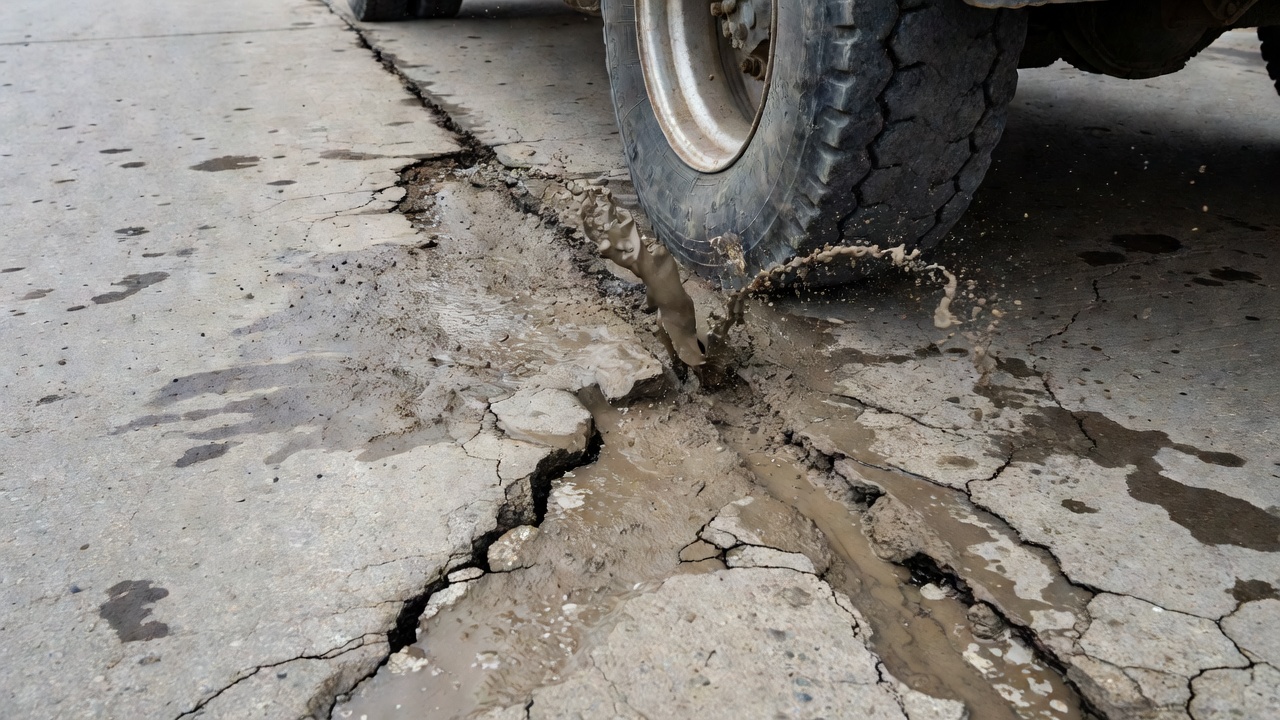
Pumping is the ejection of water and suspended fine particles from beneath the concrete slab through joints and cracks under traffic loading. The mechanism begins when free water accumulates in the pavement structure from precipitation or poor drainage. When a heavy load passes over a joint, the loaded slab deflects downward, forcing the trapped water out at high velocity through the joint opening. This water carries suspended fine particles from the subbase and subgrade. The consequences are progressive: loss of subbase support beneath the slab, void formation at the slab corner, accelerated faulting as fines deposit under the approach slab raising it relative to the departure slab, corner breaks from loss of support, and surface staining with visible mud pumping at joints.
Subbase materials that resist shear stress of 25–50 Pa do not erode for the pavement’s design life. Erodible subbase materials — particularly fine-grained soils with high silt content — are most susceptible to pumping-induced failure. The presence of free water combined with heavy traffic loading and poor LTE creates a positive feedback loop: poor LTE increases slab deflections, which increases pumping, which further reduces LTE.
Erosion and Faulting Progression
Erosion of subbase material under repeated loading creates voids under the slab, increasing slab deflections, corner stresses, and accelerating fatigue cracking. Faulting progression follows a characteristic pattern documented in FHWA HIPERPAV II: initially growing linearly with load applications, then growing nonlinearly as deterioration accelerates. Objectionable faulting for ride quality is defined as exceeding 3.3 mm (0.13 in) .
Dowel Bar Corrosion
When the protective coating on dowel bars is compromised — through coating defects, improper handling during installation, or inadequate concrete cover — chlorides from deicing salts or marine environments penetrate to the steel surface, initiating corrosion. Corrosion products (rust) occupy a larger volume than the original steel, creating tensile stresses in the surrounding concrete that can cause cracking and spalling along the joint. Loss of effective dowel cross-section reduces shear capacity, increased bearing stress on concrete creates dowel looseness, and in severe cases joint movement becomes locked by corrosion buildup.
Other Deterioration Mechanisms
Dowel looseness develops as repeated bearing stresses enlarge the hole around the dowel, reducing shear transfer efficiency. Loss of slab support from erosion voids increases deflections at the joint. Freeze-thaw damage to the concrete around the joint reduces dowel bearing capacity. Aggregate degradation from crushing and wearing of aggregate at interlock surfaces progressively reduces shear transfer capacity. Joint sealant failure allows water and incompressibles into the joint, accelerating all deterioration mechanisms.
Inspection for Load Transfer Condition
Inspection of load transfer condition combines visual inspection, non-destructive testing (NDT), and direct sampling to evaluate joint performance and determine the need for rehabilitation. Per FAA AC 150/5320-6G and ICAO Annex 14, a comprehensive inspection program addresses all mechanisms of load transfer deterioration.
Visual Inspection
Visual inspection identifies visible indicators of load transfer problems. Faulting — the vertical step between adjacent slabs — is measured with a straightedge or faultmeter. Spalling — cracking and chipping at joint edges — indicates stress concentrations from poor load transfer or dowel corrosion. Corner breaks — diagonal cracks emanating from the slab corner — indicate loss of support from pumping and erosion. Pumping stains at joints provide direct evidence of active subbase erosion. Joint sealant condition assessment identifies adhesive failure, cohesive failure, or intrusion of incompressibles that can lock the joint.
ACPA and PCI concrete pavement condition surveys categorize severity by faulting magnitude: Low severity (barely noticeable, less than 3 mm faulting), Medium severity (3–10 mm faulting with visible spalling), and High severity (more than 10 mm faulting with extensive spalling, exposed dowels, and structural distress).
FWD / HWD Testing
Per FAA AC 150/5320-6G Appendix C, FWD testing computes LTE from loaded and unloaded side deflections at each joint, computes Impulse Stiffness Modulus (ISM) = load / peak deflection, and calculates ISM_ratio (center/corner or center/joint) for concrete durability assessment: ISM_ratio < 1.5 indicates good condition, ISM_ratio 1.5–3.0 indicates questionable durability, and ISM_ratio > 3.0 indicates poor durability at the corner or joint.
Ground Penetrating Radar (GPR)
Per FAA AC 150/5320-6G Appendix E and ASTM D6432, GPR uses electromagnetic radiation in the microwave band (UHF/VHF frequencies) to measure layer thickness, locate subsurface moisture or voids, detect delamination, and locate dowel bar positions. GPR is limited in effectiveness when used in fine-grained soils (silt and clay) due to signal attenuation.
Core Sampling and Dowel Imaging
Core sampling provides direct measurement of slab thickness, reveals concrete condition at depth (durability issues, ASR, freeze-thaw damage), and verifies dowel bar position and coating condition. A core that drops out during extraction indicates a void beneath the slab and loss of support. Magnetic Imaging Tomography (MIT) per ASTM E3013/E3013M uses magnetic pulse induction (MPI) equipment for non-destructive rapid testing of dowel bar alignment, measuring horizontal skew, vertical tilt, side shift, depth, and lateral position, and computing Joint Score (JS) for comparison with JS_critical values.
Acceptance Criteria Per FAA and ICAO
FAA AC 150/5320-6G specifies that new construction dowel alignment must conform to approved plans. For existing pavements, LTE ≥ 75% is generally acceptable, LTE ≤ 60% indicates rehabilitation (load transfer restoration) is recommended, and faulting > 2.5 mm (0.1 in) means load transfer restoration should be considered. ICAO Doc 9157, Part 3 requires reporting of pavement strength via the ACR-PCR method, with technical evaluation including NDT (FWD/HWD), core sampling, and visual surveys, and mandates re-evaluation of pavement condition if traffic changes significantly.
Load Transfer and Pavement Life
The relationship between load transfer efficiency and pavement structural capacity is direct and quantifiable. Poor LTE increases the effective edge stress in the loaded slab, accelerating fatigue damage and reducing remaining life. Free-edge stresses can be 25–40% higher than interior stresses. The relationship between LTE and edge stress follows a predictable pattern: with LTE at 100% (perfect transfer), stress approximates interior condition; with LTE at 75%, stress is approximately 15–20% above interior; with LTE at 50%, stress is approximately 30% above interior; and with LTE at 0% (free edge condition), stress exceeds interior by 40% or more.
Per the FAA FAARFIELD design methodology, edge stress is reduced by 25% to account for assumed joint load transfer in design. When evaluating existing pavements, edge stresses for evaluation are back-calculated by dividing the computed edge stress by 0.75.
Condition
Threshold
Action
Deflection LTE
≤ 60%
Load transfer restoration recommended (FHWA LTR Guide)
Deflection LTE
60–75%
Monitor; consider LTR if traffic is heavy
Faulting
> 2.5 mm (0.1 in)
Grinding and/or LTR (FHWA)
Faulting
> 3.3 mm (0.13 in)
Objectionable ride quality (FHWA)
Faulting (project level)
≥ 500 μm total
Load transfer restoration warranted (FHWA)
Differential deflection
≥ 250 μm (10 mils)
Consider LTR (FHWA)
Corner deflection + high LTE
Both high
Indicates loss of support, not poor LTR
Joint Score
> JS_critical
Dowel alignment/pavement performance at risk
ISM_ratio
> 3.0
Poor concrete durability at joint/corner
Life Extension with Dowel Bar Retrofit
The FHWA Guide for Load Transfer Restoration documents that properly installed retrofitted dowels restore LTE to 70–90% from ≤ 60%, produce large improvement in LTE with decreases in maximum vertical deflections (confirmed by Heavy Vehicle Simulator testing), extend service life of structurally sound pavements by 10–15+ years, and are cost-effective when the pavement has significant remaining structural life but poor load transfer. Dowel bar retrofit is NOT recommended for pavements with D-cracking, alkali-silica reaction (ASR), or extensive slab cracking.
Joint Spacing and Pavement Life
FAA AC 150/5320-6G specifies maximum joint spacing based on slab thickness and base type. For slabs without stabilized base: ≤ 6 in (152 mm) thickness allows 12.5 ft (3.8 m) spacing; 6.5–9 in (165–229 mm) allows 15 ft (4.6 m); > 9 in (> 229 mm) allows 20 ft (6.1 m). For slabs with stabilized base: 8–10 in (203–254 mm) allows 12.5 ft (3.8 m); 10.5–13 in (267–330 mm) allows 15 ft (4.6 m); ≥ 16 in (406 mm) allows 20 ft (6.1 m). The panel aspect ratio must not exceed width-to-length ratio of 1:1.25 per FAA. FHWA specifies maximum panel length of 15 ft (4.6 m) for highways, which can be exceeded with technical analysis. Shorter joint spacing provides better performance in freeze-thaw environments and reduces joint openings, improving aggregate interlock longevity and reducing the demand on load transfer devices.
Frequently Asked Questions
A load transfer device is a structural element installed at transverse or longitudinal joints in Portland cement concrete (PCC) pavement that transfers vertical shear forces from a loaded slab to an adjacent unloaded slab. Common types include smooth round dowel bars at transverse contraction joints, deformed tie bars at longitudinal joints, aggregate interlock at saw-cut and cracked joints, and keyed joints. Without load transfer devices, differential deflection (faulting) develops as each slab moves independently under traffic, leading to corner breaks, pumping, and accelerated pavement deterioration.
Load Transfer Efficiency (LTE) is the ratio of deflection on the unloaded side of a joint to deflection on the loaded side, expressed as a percentage. It is measured using a Falling Weight Deflectometer (FWD) or Heavy Weight Deflectometer (HWD), where a known force is applied to one side of the joint and geophone sensors record the deflection response on both sides. The standard formula is LTE = (du / dl) × 100%, where du is deflection on the unloaded side and dl is deflection on the loaded side. LTE values above 75% are considered good, values between 60–75% warrant monitoring, and values below 60% typically trigger load transfer restoration measures per FHWA guidance.
Load transfer deterioration is caused by several interacting mechanisms. Pumping occurs when water trapped beneath the slab is ejected under traffic loading, carrying fine particles from the subbase and creating voids. Erosion of subbase material increases slab deflections and accelerates faulting. Dowel bar corrosion reduces the effective cross-section and shear capacity of dowels, and corrosion products can cause spalling. Dowel looseness develops from repeated bearing stresses that enlarge the hole around the dowel. Aggregate interlock degrades as joint openings exceed 0.6 mm and repeated loading crushes the interlocking aggregate particles. Joint sealant failure allows water and incompressibles into the joint, accelerating all deterioration mechanisms.
Dowel bars are smooth, round steel bars installed across transverse contraction joints. They are designed to allow horizontal joint movement (opening and closing with thermal expansion and contraction) while preventing differential vertical movement. A bond breaker is applied to one half to prevent bonding and enable joint movement. Tie bars are deformed steel bars installed across longitudinal joints. They are designed to hold joint faces together and prevent joint opening, relying on their deformed surface to bond with the concrete. Tie bars do not allow horizontal movement and do not carry axial load in the same way. Dowel bars transfer load through shear and bending; tie bars keep the joint tight so that aggregate interlock can provide load transfer.
Aggregate interlock is the natural load transfer mechanism provided by the interlocking of irregular aggregate particles exposed on the fractured face of a saw-cut and cracked joint. It is sufficient for light-duty pavements and short joint panels where joint openings remain below approximately 0.6 mm (0.024 in). For airport pavements, FAA allows aggregate interlock (without dowels) for panels less than 9 inches thick. However, aggregate interlock degrades over time due to repeated traffic loading (which crushes aggregate contact points), thermal cycling (which progressively widens joints), and moisture infiltration. Once joint openings exceed 0.6 mm, aggregate interlock is effectively lost and dowel bar retrofit may be required.
Per FAA AC 150/5320-6G, dowel bars are required in the last three transverse contraction joints from a free edge of pavement. They are required in ALL construction joints (transverse and longitudinal) unless a thickened or reinforced edge is provided. On stabilized bases, FAA notes there is little benefit to providing more than the minimum dowels in the last three joints from a free edge. Dowel dimensions must conform to FAA Table 3-6, which specifies diameter, length, and spacing based on slab thickness. Dowel diameter follows the general rule of slab thickness divided by 8, ranging from 3/4 inch diameter for 5–7 inch slabs to 2 inch diameter for 20.5–24 inch slabs.
Load Transfer Efficiency directly affects the structural capacity and remaining life of concrete pavement. Poor LTE increases the effective edge stress in the loaded slab — free-edge stresses can be 25–40% higher than interior stresses. With LTE at 75%, edge stress is approximately 15–20% above interior stress; with LTE at 50%, stress rises to approximately 30% above interior; with LTE at 0% (free edge condition), stress exceeds interior by 40%+. This stress increase accelerates slab fatigue damage, reducing the computed remaining life in FAA FAARFIELD evaluations. Per FHWA guidance, pavements with LTE ≤ 60% are candidates for load transfer restoration (dowel bar retrofit), which can extend service life by 10–15+ years when the pavement has significant remaining structural life.
Load transfer problems are detected through multiple complementary inspection methods. Visual inspection identifies faulting (vertical steps between slabs), spalling, corner breaks, and pumping stains. FWD/HWD testing is the primary quantitative method, measuring deflection LTE at each joint and computing Impulse Stiffness Modulus (ISM) ratios. The ISM_ratio (center/corner or center/joint) indicates concrete durability: < 1.5 is good, 1.5–3.0 is questionable, > 3.0 indicates poor condition. Ground Penetrating Radar (GPR) per ASTM D6432 can detect subsurface voids and locate dowel bar positions. Core sampling provides direct measurement of slab thickness and reveals concrete condition at depth. Magnetic Imaging Tomography (MIT) per ASTM E3013 non-destructively measures dowel bar alignment, computing Joint Score (JS) to quantify alignment quality against critical thresholds.
Joint spacing directly affects load transfer by controlling joint opening width. Shorter joint spacing reduces the cumulative thermal movement at each joint, keeping joints tighter and preserving aggregate interlock longer. FAA AC 150/5320-6G specifies maximum joint spacing based on slab thickness and base type: for slabs ≤ 6 inches without stabilized base, maximum spacing is 12.5 ft; for slabs 6.5–9 inches, 15 ft; for slabs > 9 inches, 20 ft. With stabilized base, spacing is reduced: 12.5 ft for 8–10 inch slabs, 15 ft for 10.5–13 inch slabs, and 20 ft for slabs ≥ 16 inches. The panel aspect ratio (width-to-length) must not exceed 1:1.25 per FAA. Shorter joint spacing also reduces slab curling and warping stresses, contributing to better long-term load transfer performance.
Dowel bar retrofit (DBR) is a rehabilitation technique where dowel bars are installed into existing concrete pavement joints to restore load transfer capacity. The process involves cutting slots across the joint at specified spacing, cleaning the slots, placing epoxy-coated dowel bars, and filling with high-early-strength patching material. DBR is indicated when deflection LTE falls below 60%, faulting exceeds 2.5 mm (0.1 in), or differential deflection exceeds 250 μm (10 mils) per FHWA guidance. Properly installed retrofitted dowels restore LTE to 70–90% from ≤ 60%, extend pavement service life by 10–15+ years, and are cost-effective when the pavement has significant remaining structural life. DBR is not recommended for pavements with D-cracking, alkali-silica reaction (ASR), or extensive slab cracking.
Faulting is a differential vertical displacement (step) between adjacent concrete slabs at a joint or crack, caused by loss of load transfer combined with pumping of subbase fines. As traffic loads cross the joint repeatedly without adequate load transfer, the loaded slab deflects more than the adjacent slab, pumping water and fine particles from beneath the slab. These fines deposit under the approach slab, progressively increasing the height differential. Faulting accelerates as deterioration increases — initially growing linearly with load applications, then nonlinearly. FHWA considers faulting > 2.5 mm (0.1 in) as requiring attention and > 3.3 mm (0.13 in) as objectionable for ride quality. Faulting is the primary visible indicator of load transfer deterioration in jointed concrete pavement.
Keyed joints (keyway joints) are structural joints where one slab has a protruding key that fits into a matching groove in the adjacent slab, providing mechanical load transfer through interlocking geometry. They are commonly formed using prefabricated U-shaped galvanized steel forms. However, FAA AC 150/5320-6G does not include keyed joints as a standard joint type for airfield pavements — FAA standard joints are Types A through F (thickened edge, hinged, doweled, dummy, doweled construction, and butt construction). Keyed joints are generally not recommended for airfield pavements serving aircraft over 30,000 lbs due to cracking from inability to accommodate thermal movements, joint faulting, and construction alignment challenges. They are more commonly used in highway and industrial pavement applications with thicker slabs.
Pumping is the ejection of water and suspended fine particles from beneath a concrete pavement slab through joints and cracks under traffic loading. The mechanism begins when free water accumulates beneath the slab. As a heavy load approaches a joint, the loaded slab deflects downward, pressurizing the water and forcing it out at high velocity through the joint opening. This water carries fine particles from the subbase or subgrade, creating voids beneath the slab corner. The ejected fines may deposit on the pavement surface as visible stains at joints. Consequences include loss of slab support, accelerated faulting (fines deposited under the approach slab), corner breaks, and progressive deterioration of load transfer. Pumping is exacerbated by erodible subbase materials, poor drainage, high slab deflections (from poor LTE), and repeated heavy traffic loading.
Dowel bars must conform to multiple material standards depending on the application and environment. The primary base material standard is ASTM A615 Grade 60 (plain carbon steel). Coated dowels follow ASTM A1078/A1078M for epoxy-coated steel dowels. Fusion-bonded epoxy coating per ASTM A775 or A934 provides 30–40 years of service life in chloride environments. Hot-dip galvanized dowels per ASTM A1094 offer 15–25 years service life at 1.2× the baseline cost. Stainless steel dowels per ASTM A955 (304, 316, 316LN grades) provide 75–100 years at 4–5× cost. FRP/GFRP dowels per ASTM D7957 offer 100+ years (immune to corrosion) at 2.5–3× cost. For European applications, EN 13877-3 governs load transfer at concrete pavement joints. ACPA M254-23 provides a comprehensive specification covering Type A, B, C, and D dowel categories for different performance requirements.
The Falling Weight Deflectometer (FWD) measures load transfer efficiency by applying a dynamic impulse load (typically 40–120 kN / 9,000–27,000 lbf) to the pavement surface through a load plate positioned adjacent to the joint edge. A series of 7–8 geophone sensors measure the resulting pavement surface deflections at precise distances from the load plate center. The critical sensors are those placed on both sides of the joint — one on the loaded slab and one on the unloaded slab. LTE is calculated as the ratio of unloaded side deflection to loaded side deflection, expressed as a percentage. Per FAA AC 150/5320-6G Appendix C, testing should be performed at panel center (for concrete modulus determination), at the joint (for LTE), and at the panel corner (for support conditions and void detection). Temperature effects must be considered — best testing occurs when ambient temperature is ≤ 21°C (70°F) and slabs are flat (not curled), typically in early morning and late afternoon.
The relationship between deflection-based LTE and stress-based LTE is not linear. Research documented in the FHWA Guide for Load Transfer Restoration shows that a deflection LTE of 60% may correspond to a stress LTE of only approximately 22%. This means stress reduction from load transfer is much smaller than deflection reduction would suggest. The practical implication is that even pavements with moderate deflection LTE may experience significantly higher edge stresses than expected, accelerating fatigue damage. FAA FAARFIELD design methodology reduces edge stress by 25% to account for assumed joint load transfer in design. When evaluating existing pavements, edge stresses are back-calculated by dividing computed edge stress by 0.75. This relationship underscores why deflection-based LTE thresholds for rehabilitation (≤ 60%) are conservative and why achieving high LTE (≥ 85–95%) with proper dowel design is critical for long pavement life.
Assess Joint Load Transfer with Precision
TarmacView's AI-powered pavement inspection platform detects faulting, spalling, and joint distress indicators correlated with load transfer deterioration. Integrate FWD data and visual inspection into a unified condition assessment workflow for airport and highway concrete pavements.
Faulting at Joints and Cracks in Concrete Pavements
Faulting is the vertical displacement at a transverse joint or crack in concrete pavement, creating a 'step' felt by vehicles crossing the joint. It results fro...
Tie bars are deformed steel bars placed across longitudinal joints in concrete pavement to prevent lane separation and hold adjacent slabs tightly together. Unl...
Dowel bars are smooth, round steel bars placed across transverse joints in jointed plain concrete pavement (JPCP) to transfer wheel loads between adjacent slabs...
30 min read
Pavement Design
Concrete Runway
+3
Cookie Consent We use cookies to enhance your browsing experience and analyze our traffic. See our privacy policy.