Longitudinal Cracking in Asphalt and Concrete Pavements
Longitudinal cracks run parallel to the pavement centerline or direction of travel. Causes include poor construction joint bonding, reflective cracking from underlying layers, thermal stress, and differential settlement. FHWA LTPP and TxDOT define severity levels based on crack width, spalling, and faulting. Covers mechanics, classification, measurement protocols, and automated crack orientation detection with AI.
Longitudinal Cracking in Asphalt and Concrete Pavements
1. Definition and Orientation
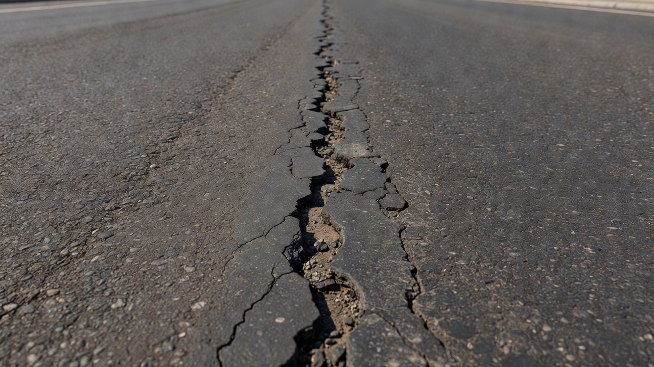
Longitudinal cracking is a pavement distress characterized by cracks that run predominantly parallel to the pavement centerline or the direction of traffic flow. In the FHWA Long-Term Pavement Performance (LTPP) Distress Identification Manual (Fifth Revised Edition, FHWA-HRT-13-092), longitudinal cracking is formally defined as “cracks predominantly parallel to pavement centerline” with specific notation that “location within the lane (wheel path versus non-wheel path) is significant.” This orientation distinguishes longitudinal cracks from transverse cracks (which run perpendicular to the centerline), block cracking (which forms rectangular patterns), and fatigue or alligator cracking (which forms interconnected chicken-wire patterns).
The distinction between longitudinal and transverse crack orientation is fundamental to pavement distress taxonomy because the mechanisms causing each type differ substantially. Longitudinal cracks typically arise from longitudinal construction joints, reflective cracking from underlying pavement layers, thermal and moisture-induced shrinkage stresses oriented transversely, top-down cracking mechanisms, or differential movement beneath the pavement surface. The crack orientation provides direct diagnostic information about the root cause and appropriate remediation strategy.
In the FHWA LTPP taxonomy, longitudinal cracking is subdivided into two distinct categories based on transverse placement within the lane: ACP 4a — Wheel Path Longitudinal Cracking and ACP 4b — Non-Wheel Path Longitudinal Cracking. Wheel path longitudinal cracking is cracking that occurs within the defined wheel paths (typically the trafficked areas where tires repeatedly pass) and is often load-associated, frequently representing the earliest stage of fatigue (alligator) cracking. Non-wheel path longitudinal cracking occurs outside the wheel paths and is typically associated with environmental factors, construction deficiencies, or reflection from underlying layers. This classification is critical because it directly informs the probable cause and the appropriate maintenance response.
The TxDOT Pavement Management Information System (PMIS) Rater’s Manual defines longitudinal cracking as “cracks or breaks that run approximately parallel to the pavement centerline and may appear anywhere along a shoulder or driving lane.” For rating purposes in the TxDOT system, cracks must be at least 3 mm (1/8 inch) wide, show evidence of spalling or pumping, or have been previously sealed to be eligible for rating. This minimum width threshold ensures that only structurally significant cracks are recorded during network-level surveys, avoiding the counting of superficial surface checking or hairline cracks that do not compromise pavement integrity.
The ASTM D6433 Standard Practice for Roads and Parking Lots Pavement Condition Index (PCI) Surveys also addresses longitudinal cracking, measuring it as a linear distress in feet or meters of affected crack length. In the ASTM PCI methodology, longitudinal cracking is one of 19 distinct distress types for asphalt surfaces and contributes to the overall PCI score through a density-based deduct value system. The PCI procedure counts both wheel path and non-wheel path longitudinal cracks, with the severity level determined by crack width and the presence of spalling or adjacent random cracking.
2. Causes of Longitudinal Cracking
Poor Construction Joint Bonding
The most common cause of longitudinal cracking in asphalt pavements is poor construction at longitudinal joints. During paving operations, hot-mix asphalt (HMA) is placed in parallel passes or lanes, creating longitudinal joints where adjacent passes meet. These joints are the most difficult portion of a pavement to compact properly because the roller operator must position the equipment such that it fully compacts the joint without either (1) partially resting its weight on the adjacent already-compacted pavement (which bridges over the joint and prevents adequate compaction of the newly placed mat), or (2) staying too far from the edge and leaving the joint uncompacted. The result is a zone of higher air voids, lower density, and weaker material that is predisposed to cracking under traffic loading.
The density differential between the joint area and the main pavement mat can be significant. Studies have shown that longitudinal joint density can be 3 to 5 percent lower than the mat density, resulting in air void contents that exceed the standard specification limits. This differential creates a permeability contrast where water preferentially infiltrates through the joint, accelerating oxidative aging of the binder and weakening the aggregate interlock. When the joint is located in the wheel path — a common but poor practice — traffic loads repeatedly stress this already weak zone, and longitudinal cracking typically appears within the first 2 to 5 years of service life.
The FHWA and industry best practices recommend constructing longitudinal joints outside the wheel path so that they are only infrequently loaded. Proper joint construction techniques include using a notched wedge joint configuration, applying tack coat to the vertical face of the cold joint, ensuring the hot mat overlaps the cold lane by 25 to 50 mm (1 to 2 inches), and using a breakdown roller that operates with the drive wheel facing the joint. Despite these recommendations, many pavements continue to exhibit joint-related longitudinal cracking because of production pressure, insufficient rolling patterns, or inadequate quality control during construction.
Reflective Cracking from Underlying Layers
Reflective cracking occurs when cracks or joints in an underlying pavement layer propagate upward through an HMA overlay. An underlying crack or joint experiences small horizontal and vertical movements due to thermal expansion and contraction, traffic loading, or moisture changes. These movements generate tensile and shear stresses at the base of the overlay that concentrate directly above the underlying discontinuity. Over time, these repeated stress concentrations cause a crack to initiate at the bottom of the overlay and propagate upward to the surface, manifesting as a longitudinal crack that mirrors the location and orientation of the underlying discontinuity.
When the underlying pavement is portland cement concrete (PCC) with longitudinal joints, the reflective cracks in the AC overlay appear as longitudinal cracks that align with the underlying joint locations. The slab dimensions beneath the AC surface must be known to identify whether a longitudinal crack is a reflection crack at a joint. In the FHWA LTPP system, reflection cracking at joints (ACP 5) is recorded as longitudinal cracking (ACP 4) or transverse cracking (ACP 6) on LTPP surveys, acknowledging that the oriented nature of reflective cracks places them within the same measurement taxonomy.
Interlayer stress-absorbing membrane interlayers (SAMIs), paving fabrics, and stress-relief interlayers are common mitigation strategies designed to absorb the tensile strains at the overlay base and delay or prevent reflective cracking. However, even with these treatments, reflective cracks can eventually propagate through, particularly under heavy traffic or extreme thermal cycling. The rate of reflective cracking depends on the stiffness and thickness of the overlay, the amplitude of joint movement, the traffic loading, and the ambient temperature regime.
Thermal Shrinkage Stress
Thermal shrinkage is a primary cause of longitudinal cracking in both asphalt and concrete pavements. When the pavement surface cools, tensile stresses develop as the material attempts to contract but is restrained by the underlying layers and subgrade. In asphalt pavements, age-hardening of the binder reduces the material’s relaxation capacity, making the surface more brittle and susceptible to thermal cracking. When the tensile stress exceeds the tensile strength of the pavement material, a crack initiates. Because thermal stresses in a continuous pavement are predominantly oriented transversely (perpendicular to the direction of paving), the resulting cracks are often longitudinal — running parallel to the pavement centerline.
In rigid (concrete) pavements, longitudinal cracking from thermal causes is frequently associated with delayed or inadequate saw cutting of joints. During concrete pavement construction, contraction joints must be sawn as soon as the concrete can support the sawing equipment without raveling — typically within 4 to 12 hours after placement, depending on ambient temperature and concrete mix characteristics. If the joints are cut too late, or if the slab is too wide for the specified joint spacing, the thermal and shrinkage stresses that develop during the early age of the concrete can exceed its developing tensile strength, resulting in uncontrolled longitudinal cracking at locations other than the intended joint.
The relationship between slab geometry and thermal cracking is well documented. For jointed concrete pavements, the ratio of slab width to slab length influences the magnitude of curling and warping stresses. Slabs that exceed approximately 4.5 meters (15 feet) in width are at increased risk of longitudinal cracking, particularly when constructed on swelling or moisture-sensitive subgrades. Warping stresses from temperature differentials between the top and bottom of the slab (daytime: top warmer, bottom cooler; nighttime: top cooler, bottom warmer) produce tensile stresses at the slab surface or bottom that can initiate longitudinal cracks.
Differential Settlement
Differential settlement beneath the pavement surface produces longitudinal cracking through bending and shear stresses that exceed the material’s capacity. This mechanism is common in several scenarios: embankment widening where new fill consolidates differently from existing fill; utility trench backfill that settles differentially compared to undisturbed adjacent soil; interface zones between cut and fill sections; and areas where the subgrade soil experiences moisture-induced volume changes (swelling clays).
When differential settlement occurs, the pavement section is subjected to bending moments that generate tensile stresses at either the surface or bottom of the pavement structure. If the tensile stress exceeds the modulus of rupture of the material, a crack initiates at the location of maximum bending stress — typically at the edge of the settlement zone. Because settlement typically varies gradually in the longitudinal direction (along the alignment), the resulting crack runs longitudinally, approximately parallel to the centerline, following the boundary of the settled area.
The width of settlement-related longitudinal cracks is typically not uniform along the crack length. The crack is widest at the location of maximum differential movement and may decrease or even close at the ends. Seasonal moisture changes in expansive subgrade soils cause these cracks to open and close cyclically — the crack is widest during dry periods when the soil shrinks and narrowest during wet periods when the soil swells. This cyclic movement makes settlement-related cracks particularly difficult to seal permanently and requires crack sealants with high elasticity and adhesive strength.
HMA Fatigue and Top-Down Cracking
In the wheel path, longitudinal cracking can represent the earliest stage of fatigue (alligator) cracking in asphalt pavements. When the pavement structure is subjected to repeated traffic loadings, tensile strains develop at the bottom of the asphalt layer. These strains accumulate over millions of load applications, eventually initiating a crack at the bottom of the HMA layer that propagates upward. The first visible manifestation at the surface is often a single longitudinal crack in the wheel path. As additional load applications accumulate, adjacent parallel cracks develop, and transverse connecting cracks form, eventually creating the characteristic interconnected chicken-wire or alligator pattern.
Top-down cracking represents an alternative cracking mechanism that initiates at the pavement surface and propagates downward. In pavements of substantial thickness for the applied loading — typically HMA layers greater than 150 to 200 mm (6 to 8 inches) — the critical tensile strains may occur at the surface rather than at the bottom of the layer. Surface-initiated cracks arise from the combined effects of tire-induced tensile stresses at the pavement surface (particularly at the edge of the tire contact area), thermal stresses, and age-hardening of the surface binder. The aged surface binder becomes more brittle and less capable of relaxing stresses, making it susceptible to cracking under the high, localized tensile strains generated by loaded tires.
Top-down longitudinal cracks typically appear as single, relatively straight cracks in or near the wheel path. Unlike bottom-up fatigue cracks, which typically develop as multiple parallel cracks before forming the alligator pattern, top-down cracks often remain as solitary cracks for extended periods. The distinction between bottom-up and top-down cracking mechanisms is important for pavement design and rehabilitation. Bottom-up cracking indicates a structural deficiency that may require thickness increase, while top-down cracking suggests that surface durability, binder aging resistance, or mixture design improvements are needed.
3. FHWA LTPP Severity Levels for Asphalt Concrete Pavements
The FHWA LTPP Distress Identification Manual defines three distinct severity levels for longitudinal cracking in asphalt concrete-surfaced pavements. These severity levels are based on crack width, the presence and condition of sealant, and the presence of adjacent random cracking within 300 mm (0.3 m) of the primary crack.
Severity Level
Crack Width Criterion
Adjacent Random Cracking Criterion
Low
Mean width ≤ 6 mm, or sealed crack with sealant in good condition and undetermined width
Not applicable
Moderate
Mean width > 6 mm and ≤ 19 mm
Mean width ≤ 19 mm with adjacent low severity random cracking within 0.3 m
High
Mean width > 19 mm
Mean width ≤ 19 mm with adjacent moderate to high severity random cracking within 0.3 m
The Low severity level includes cracks that are tight (≤ 6 mm mean width) and show no significant deterioration. Sealed cracks where the sealant is in good condition and the crack width cannot be physically determined are also rated as low severity because the sealant is performing its intended function of preventing moisture infiltration. LTPP specifies that sealant is not considered to be in good condition unless at least 1 meter of continuous sealant in good condition is present. For cracks shorter than 1 meter, the sealant must be present and in good condition over the entire crack length.
The Moderate severity level includes cracks wider than 6 mm but not exceeding 19 mm mean width. It also includes cracks that are 19 mm or narrower but have adjacent low severity random cracking within 0.3 m of the primary crack. The presence of adjacent random cracking indicates that the pavement material around the crack is beginning to deteriorate, with secondary cracks developing parallel or branching from the primary longitudinal crack. This represents a more advanced stage of distress than an isolated crack.
The High severity level includes cracks exceeding 19 mm mean width, or any crack (regardless of width) with adjacent moderate to high severity random cracking within 0.3 m. Cracks at this severity level allow significant moisture infiltration, may be associated with raveling or spalling of the crack edges, and represent a significant compromise of pavement integrity. High severity longitudinal cracking in the wheel path often requires removal and replacement of the cracked pavement layer rather than simple crack sealing.
For wheel path longitudinal cracking (ACP 4a) , any crack that has associated random cracking or meanders and has a quantifiable area is rated as fatigue cracking (ACP 1) rather than longitudinal cracking. This rule ensures that the onset of alligator fatigue cracking is correctly classified under the fatigue cracking distress type rather than being double-counted as longitudinal cracking.
For non-wheel path longitudinal cracking (ACP 4b) , the same severity level criteria apply, but the measurement and recording are performed separately from wheel path cracking. This separation allows pavement managers to track whether cracking is load-associated (wheel path) or environmentally/construction-related (non-wheel path), which directly informs rehabilitation strategy selection.
4. TxDOT Classification of Longitudinal Cracking
The Texas Department of Transportation (TxDOT) Pavement Management Information System (PMIS) and the TxDOT Pavement Manual provide a distinct classification framework for longitudinal cracking that differs from the FHWA LTPP system in several important aspects. The TxDOT system is designed for network-level pavement condition surveys conducted by trained raters who assess pavement condition using standardized protocols.
In the TxDOT flexible pavement rating system, longitudinal cracking is defined as “cracks or breaks that run approximately parallel to the pavement centerline and may appear anywhere along a shoulder or driving lane.” For rating purposes, cracks must be at least 3 mm (1/8 inch) wide, show evidence of spalling or pumping, or have been previously sealed. Measurement is expressed in linear feet per 100-foot station, providing a normalized density measurement that facilitates comparison across pavement sections of varying length.
A critical threshold in the TxDOT system is the failure criterion: longitudinal cracking wider than 50 mm (2.0 inches) or faulted greater than 50 mm (2.0 inches) is rated as a failure, not as longitudinal cracking. This reclassification reflects the severity of such wide or faulted cracks, which represent a structural integrity concern requiring immediate attention. Failure-rated cracks trigger different maintenance and rehabilitation responses than lower-severity longitudinal cracks.
The TxDOT classification notes that the transverse placement of the crack within the lane is diagnostically significant. Longitudinal cracks in the wheel path are “load associated (a precursor of alligator cracking in the wheel path),” while longitudinal cracks outside the wheel path are “environmentally associated.” This distinction mirrors the FHWA LTPP separation into wheel path and non-wheel path categories, though TxDOT does not require separate rating of these two categories in their standardized protocols.
For rigid (concrete) pavements, TxDOT’s classification under the CPCD (Concrete Pavement, Contraction Design) category uses a different metric. “Slabs with Longitudinal Cracks” are counted when the crack exceeds half the slab length and shows severe spalling (greater than 25 mm or 1 inch wide on either side for more than half its length) or is faulted at least 6 mm (1/4 inch). Slabs meeting these criteria are counted regardless of the number of longitudinal cracks present. This approach focuses on slab-level condition assessment rather than linear crack measurement.
5. Measurement Protocols for Longitudinal Cracking
Length Measurement
Longitudinal cracking is quantified as linear length at each severity level. The FHWA LTPP protocol requires recording length in meters for asphalt concrete pavements, while the ASTM D6433 PCI method uses either feet or meters. The measurement captures the physical extent of the crack, not the area affected. For wheel path longitudinal cracking (ACP 4a), the recorded length includes only the portion of the crack within the defined wheel path boundaries. For non-wheel path longitudinal cracking (ACP 4b), the length includes cracks located outside the wheel paths.
The TxDOT system measures longitudinal cracking in linear feet per 100-foot station. This normalized metric allows direct comparison between pavement sections of different lengths. A longitudinal crack that extends for 50 linear feet within a 100-foot station would be recorded as 50 feet per station.
Width Measurement
Crack width is the primary determinant of severity level. The FHWA LTPP protocol specifies that crack width be measured using a crack width gauge or thin feeler gauge, inserted at multiple points along the crack to determine the mean width. The crack width gauge is a calibrated tool with incremental thickness markings that allows the rater to determine the widest gap at the pavement surface.
For sealed cracks, if the sealant is in good condition and the crack width cannot be physically determined, the crack is rated at the severity level appropriate for a crack that has been effectively maintained. The LTPP protocol requires that at least 1 meter of continuous sealant in good condition must be present before the sealed portion can be counted. If the sealant is deteriorated, failed, or missing, the crack is rated based on its actual measured width regardless of whether sealant was originally applied.
Faulting Measurement
In rigid pavements, faulting — the vertical displacement of one side of a crack relative to the other — is an additional severity criterion. FHWA LTPP defines faulting thresholds for longitudinal cracking in jointed concrete pavements: moderate severity includes faulting up to 13 mm, and high severity includes faulting of 13 mm or greater. Faulting is measured using a faultmeter or a straightedge placed across the crack with a graduated wedge or ruler to measure the elevation difference.
TxDOT specifies that longitudinal cracks faulted greater than 50 mm (2.0 inches) are rated as failures. This high threshold reflects the significant ride quality and structural concerns associated with severely faulted cracks.
Location Documentation
Accurate location documentation is essential for longitudinal cracking surveys. Raters must record the station (chainage) range over which the cracking occurs, the lane and direction of travel, and the transverse placement within the lane (wheel path or non-wheel path). Many agencies use digital data collection systems with GPS integration that automatically capture the spatial coordinates of observed distress, enabling spatial analysis of crack patterns and correlation with construction records, traffic data, and environmental factors.
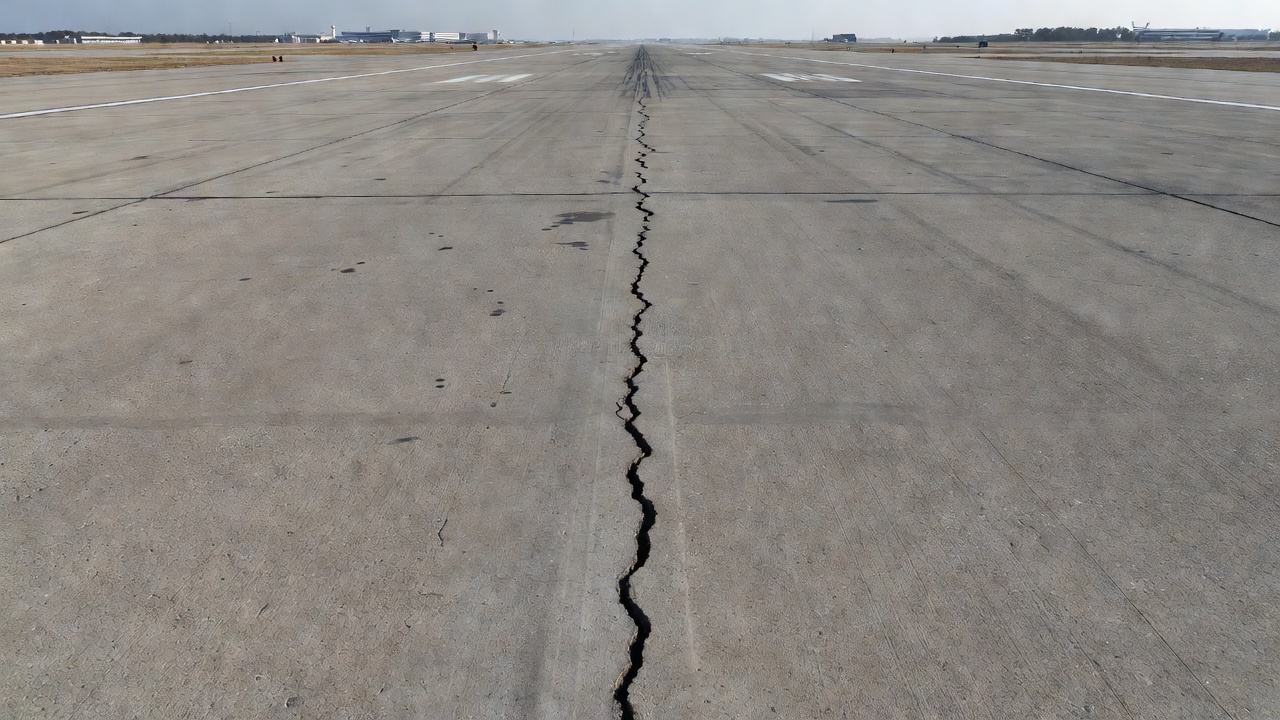
6. Longitudinal Cracking in Rigid (Concrete) Pavements
Longitudinal cracking in portland cement concrete (PCC) pavements has distinct characteristics, causes, and classification criteria that differ from longitudinal cracking in asphalt pavements. The FHWA LTPP Distress Identification Manual dedicates a separate chapter (Chapter 2) to distresses in jointed portland cement concrete surfaces, with longitudinal cracking as a distinct distress type (JCP 3).
In jointed concrete pavements, longitudinal cracks are cracks that run predominantly parallel to the pavement centerline. These cracks may be straight or may curve slightly along their length. The causes of longitudinal cracking in rigid pavements include: insufficient or delayed saw cutting of longitudinal joints; slab width that exceeds the structural capacity of the concrete section to resist curling and warping stresses; loss of foundation support from erosion, pumping, or subgrade volume change; moisture gradient-induced warping; and thermal gradient-induced curling.
The severity levels for longitudinal cracking in JCP differ from those for asphalt pavements:
Severity Level
Crack Width
Spalling
Faulting
Low
< 3 mm
No spalling
No measurable faulting
Moderate
≥ 3 mm and < 13 mm
< 75 mm
Up to 13 mm
High
≥ 13 mm
≥ 75 mm
≥ 13 mm
For measurement purposes in rigid pavements, the FHWA LTPP protocol requires recording the length in meters of longitudinal cracking at each severity level, plus the length with sealant in good condition. The protocol also includes specific rules for distinguishing between longitudinal cracking and spalling at joints: when a crack is within 0.3 m of a joint for only a portion of its length, that portion is recorded as spalling, and the remainder is recorded as longitudinal cracking.
TxDOT’s classification for concrete pavements under the CPCD category uses a slab-based metric. Slabs with longitudinal cracks that exceed half the slab length and show severe spalling (> 25 mm wide for more than half the crack length) or faulting ≥ 6 mm are counted. This approach emphasizes the functional impact of the cracking rather than the linear extent alone. Once a slab meets the criteria, it is counted as one affected slab regardless of how many longitudinal cracks are present.
In continuously reinforced concrete pavement (CRCP) , longitudinal cracking patterns differ from jointed pavements. CRCP contains continuous longitudinal reinforcement (typically 0.6 to 0.7 percent steel by cross-sectional area) that controls the spacing and width of naturally occurring transverse cracks. Longitudinal cracks in CRCP can develop from corrosion-induced cracking along the reinforcement plane, from loss of support causing bending stresses, or from punchout formation where closely spaced transverse cracks connect via a short longitudinal crack. The TxDOT rating system for CRCP focuses on punchouts and spalled cracks rather than counting isolated longitudinal cracks.
The FAA Advisory Circular 150/5380-6C, Guidelines and Procedures for Maintenance of Airport Pavements, provides additional guidance specific to airport concrete pavements. For rigid airport pavements, longitudinal cracking that is wider than 6 mm (1/4 inch) or shows spalling or faulting requires repair to prevent FOD generation and moisture infiltration. The FAA recommends crack routing and sealing for tight, non-working cracks and full-depth slab replacement for severely deteriorated longitudinal cracks.
7. Detection and Classification of Longitudinal Cracking by AI
Modern computer vision and artificial intelligence techniques have revolutionized the detection and classification of longitudinal cracking in pavement condition surveys. Deep learning models — particularly convolutional neural networks (CNNs) and transformer architectures — can automatically identify cracks in pavement surface images, classify their orientation, and measure their geometric properties with accuracy approaching or exceeding human raters.
The core technical challenge in automated longitudinal crack detection is orientation classification. A crack detection model must distinguish between longitudinal cracks (parallel to the direction of travel), transverse cracks (perpendicular), diagonal cracks, and non-oriented distress patterns like block cracking or alligator cracking. This classification typically occurs at the pixel level through semantic segmentation, where each pixel in the input image is assigned to a class label (e.g., “longitudinal crack,” “transverse crack,” “alligator cracking,” “background”).
State-of-the-art models such as U-Net, DeepLabv3+, and Mask R-CNN have been adapted for pavement crack segmentation. The training process requires large datasets of annotated pavement images where human experts have manually labeled each crack pixel with its orientation class. Public datasets such as Crack500, GAPs (German Asphalt Pavement Distress), and CFD (Crack Forest Dataset) provide thousands of labeled images. Training typically involves data augmentation (rotation, scaling, brightness adjustment) to improve model robustness to varying lighting conditions, pavement textures, and crack morphologies.
The FHWA LTPP classification criteria — specifically the wheel path versus non-wheel path distinction — can be incorporated into AI-based analysis by integrating the crack detection results with lane geometry information. If the camera system captures the lane markings and the vehicle path, the AI system can determine whether detected longitudinal cracks fall within or outside the wheel path zones, enabling automated classification into ACP 4a and ACP 4b.
Crack width measurement by AI uses pixel-level segmentation masks combined with camera calibration parameters. The distance per pixel is determined using known reference dimensions in the image (lane width, pavement marking dimensions) or through direct camera calibration. The mean crack width is computed along the crack centerline, and severity levels according to FHWA LTPP thresholds (≤ 6 mm, 6-19 mm, > 19 mm) are automatically assigned.
The TarmacView analysis pipeline incorporates these AI techniques to provide accurate, repeatable longitudinal crack detection and classification. By processing high-resolution pavement surface images captured by inspection vehicles or drones, the system generates distress maps showing the location, orientation, length, width, and severity of each detected longitudinal crack. This automated approach eliminates inter-rater variability, reduces survey costs, and enables large-scale pavement condition assessment that would be impractical with manual surveys alone.
8. Maintenance and Repair Strategies
The appropriate maintenance or repair strategy for longitudinal cracking depends on the severity, cause, extent, and activity (whether the crack is working or non-working) of the cracking. The FHWA LTPP and FAA AC 150/5380-6C provide guidance on maintenance strategies that range from routine crack sealing to full-depth replacement.
Crack Sealing and Filling
Crack sealing is the primary treatment for low severity longitudinal cracks (width ≤ 6 mm for asphalt, < 3 mm for concrete). The process involves cleaning the crack of debris and moisture using compressed air or hot air lances, applying a hot-applied rubberized asphalt sealant that bonds to the crack faces, and allowing the sealant to cure before traffic is allowed on the surface. Crack sealing prevents moisture infiltration into the pavement structure, which is essential because water trapped in the pavement accelerates stripping of asphalt from aggregate, weakens unbound base layers, and causes freeze-thaw damage in cold climates.
The FAA AC 150/5380-6C recommends crack sealing for flexible airport pavement cracks up to 6 mm (1/4 inch) wide. For wider cracks (6 to 25 mm), the FAA recommends routing the crack to create a reservoir for the sealant, typically 12 to 18 mm wide and 12 to 18 mm deep. The routing process removes deteriorated crack edges and provides a clean surface for sealant adhesion. The rout-and-seal method significantly extends the service life of the sealant compared to simple sealing without routing.
For working cracks — cracks that experience significant horizontal movement due to thermal cycling — a high-elasticity sealant with minimum 500 percent elongation is required. Non-working cracks can be treated with lower-cost crack filling materials that have lower elasticity requirements. Determining crack activity requires measurements taken during different seasons: the crack width is measured during both summer (maximum closure) and winter (maximum opening), and the difference indicates the magnitude of movement.
Partial-Depth and Full-Depth Repair
Partial-depth repair is appropriate for moderate severity longitudinal cracks where the upper portion of the pavement is deteriorated but the lower portion remains structurally sound. The process involves saw-cutting a rectangular area centered on the crack to a depth of 50 to 100 mm (2 to 4 inches), removing the deteriorated material, cleaning the cavity, applying a tack coat to the vertical faces, and placing and compacting hot-mix asphalt patching material. Partial-depth repair removes the cracked and deteriorated surface material while preserving the intact lower pavement structure.
Full-depth repair is required for high severity longitudinal cracks (> 19 mm width or with severe spalling), particularly cracks that exhibit faulting or are located in the wheel path. The repair involves saw-cutting the full pavement thickness, removing all cracked material, preparing the base or subgrade as needed, placing and compacting HMA in lifts, and ensuring proper bonding between the patch and the existing pavement. For concrete pavements, full-depth repair of longitudinal cracks typically requires slab replacement with proper dowel bar installation at transverse joints to ensure load transfer.
The FAA AC 150/5380-6C provides detailed repair procedure specifications for flexible pavement longitudinal cracking. Appendix A of the AC includes standard repair details showing crack routing geometry, partial-depth repair dimensions, and full-depth repair configurations. For airport pavements, all repairs must be designed to prevent FOD generation — saw-cut edges must be clean, patch surfaces must be flush with the surrounding pavement, and materials must have adequate durability to resist jet blast and fuel spillage.
Preventative Strategies
Preventing longitudinal cracking begins with proper design and construction. For asphalt pavements, longitudinal joint construction best practices include: placing the joint outside the wheel path; applying adequate tack coat to the cold joint face; ensuring the hot mat overlaps the cold lane by 25 to 50 mm; achieving target density within 2 percent of mat density at the joint; and using infrared joint heaters to raise the temperature of the cold edge before the new mat is placed. For concrete pavements, timely saw cutting of longitudinal joints — within 4 to 12 hours of placement depending on temperature — is the most critical factor in preventing uncontrolled longitudinal cracking.
The Table 6-1 in FAA AC 150/5380-6C provides a quick guide for maintenance and repair of common flexible pavement surface problems. For longitudinal cracks, the guide recommends crack sealing as the primary treatment for tight cracks, partial-depth repair for moderately spalled cracks, and full-depth repair for wide, spalled, or faulted cracks. For rigid pavement longitudinal cracking, Table 6-2 recommends crack sealing for tight cracks and slab replacement for cracks with significant spalling, faulting, or multiple cracks in the same slab.
Summary
Longitudinal cracking is one of the most prevalent and diagnostically significant distress types in both flexible (asphalt) and rigid (concrete) pavements. Its orientation parallel to the pavement centerline distinguishes it from transverse, block, and fatigue cracking, and its location within the lane (wheel path versus non-wheel path) provides critical diagnostic information about its cause. The FHWA LTPP Distress Identification Manual provides the most widely adopted classification framework, defining three severity levels based on crack width, spalling, and faulting thresholds. TxDOT, ASTM D6433, and FAA AC 150/5380-6C offer complementary classification and maintenance guidance tailored to specific applications and jurisdictions.
The causes of longitudinal cracking span construction deficiencies (poor joint compaction), structural mechanisms (reflective cracking, HMA fatigue, top-down cracking), environmental factors (thermal shrinkage, moisture-induced volume changes), and foundation issues (differential settlement). Accurate diagnosis of the root cause is essential for selecting the appropriate maintenance or rehabilitation strategy, which ranges from routine crack sealing for low severity cracks to full-depth removal and replacement for high severity cracks.
Advances in AI-based crack detection and classification — using deep learning semantic segmentation models — enable automated, repeatable, and cost-effective longitudinal crack surveys that align with established FHWA LTPP, TxDOT, and ASTM protocols. These technologies are transforming pavement management by providing detailed, quantitative distress data at network scale with minimal human effort.
Frequently Asked Questions
Longitudinal cracking is a pavement distress characterized by cracks that run predominantly parallel to the pavement centerline or the direction of traffic. In the FHWA LTPP Distress Identification Manual, longitudinal cracking is further classified by its location within the lane: wheel path longitudinal cracking (within the defined wheel paths) and non-wheel path longitudinal cracking (outside the wheel paths). This distinction is significant because wheel path longitudinal cracking is often load-associated and may indicate the onset of fatigue (alligator) cracking, while non-wheel path cracking is typically caused by environmental factors, poor joint construction, or reflective cracking from underlying layers.
Longitudinal cracking has multiple causative mechanisms. Poor construction joint compaction is the most common cause — joints between adjacent paving passes are difficult to compact properly, creating a weak plane that cracks under traffic. Reflective cracking occurs when cracks or joints in underlying pavement layers propagate upward through an overlay. Thermal shrinkage of the asphalt surface or underlying stabilized base can cause tensile stresses that exceed the material's tensile strength, producing longitudinal cracks. HMA fatigue in the wheel path represents the earliest stage of alligator cracking. Top-down cracking initiates at the pavement surface due to aged, brittle asphalt combined with tire-induced tensile stresses. Differential settlement from embankment consolidation, widening interfaces, or swelling subgrade soils also produces longitudinal cracking.
The FHWA LTPP Distress Identification Manual defines three severity levels for longitudinal cracking in asphalt concrete pavements. Low severity: a crack with mean width ≤ 6 mm, or a sealed crack with sealant in good condition and undetermined width. Moderate severity: a crack with mean width > 6 mm and ≤ 19 mm, or any crack with mean width ≤ 19 mm with adjacent low severity random cracking within 0.3 m. High severity: a crack with mean width > 19 mm, or any crack with mean width ≤ 19 mm with adjacent moderate to high severity random cracking within 0.3 m. For jointed concrete pavements, the thresholds differ: low severity is crack width < 3 mm with no spalling or faulting, moderate is width ≥ 3 mm and < 13 mm or spalling < 75 mm or faulting up to 13 mm, and high is width ≥ 13 mm or spalling ≥ 75 mm or faulting ≥ 13 mm.
Longitudinal cracking is measured in linear meters (or linear feet in US customary units) of affected crack length at each severity level. The FHWA LTPP protocol requires recording the length separately for wheel path longitudinal cracking (4a) and non-wheel path longitudinal cracking (4b). Crack width is measured using a crack width gauge or thin feeler gauge, with the mean width determining the severity level. TxDOT requires cracks to be at least 1/8-inch wide or show evidence of spalling/pumping or have been previously sealed before rating. Longitudinal cracking wider than 2.0 inches or faulted greater than 2.0 inches is rated as a failure in the TxDOT system. For sealed cracks, if at least 1 meter of continuous sealant in good condition is present, the sealed length is recorded at the appropriate severity level.
Improve Your Pavement Condition Assessment
Accurate longitudinal crack detection and classification is essential for effective pavement management. Our AI-powered analysis tools help you identify, measure, and track crack distress with precision and consistency.
Transverse Cracking in Asphalt and Concrete Pavements
Transverse cracks run perpendicular to the pavement centerline, most commonly caused by thermal contraction at low temperatures or reflective cracking from unde...
Block cracking is a pattern of interconnected rectangular cracks dividing the pavement surface into roughly rectangular blocks typically 0.3 to 3 m in size. Unl...
Alligator cracking — also called fatigue cracking — is an interconnected crack pattern resembling alligator skin that indicates structural failure of the asphal...
30 min read
pavement-defects
Asphalt Pavement
+3
Cookie Consent We use cookies to enhance your browsing experience and analyze our traffic. See our privacy policy.