Magnetic Particle Testing (MT) for Steel Structures
Magnetic Particle Testing (MT) is a surface and near-surface NDT method for ferromagnetic materials where magnetic flux leakage at discontinuities attracts fine magnetic particles, visually revealing cracks, laps, seams, and other defects. It is a primary method for steel bridge member and weld inspection.
Magnetic Particle Testing (MT) for Steel Structures
1. Principle of Magnetic Particle Testing
Magnetic Particle Testing (MT), also designated as Magnetic Particle Inspection (MPI), is a non-destructive testing method that detects surface and near-surface discontinuities in ferromagnetic materials — primarily iron, steel, nickel, cobalt, and their alloys. The method is founded on the physical principle of magnetic flux leakage (MFL) at discontinuities within a magnetized ferromagnetic component.
1.1 Fundamental Physics
When a magnetic field is introduced into a ferromagnetic part, magnetic flux lines (lines of force) flow uniformly through the material in a defect-free condition. Ferromagnetic materials have high magnetic permeability (relative permeability μr typically 100–5,000+), meaning they readily concentrate and conduct magnetic flux. Air and non-metallic materials have a relative permeability of approximately 1.
A discontinuity — such as a crack, void, inclusion, lap, or seam — creates an abrupt change in magnetic reluctance (the magnetic analogue of electrical resistance). Because the permeability of air or non-metallic inclusion material is dramatically lower than that of the surrounding ferromagnetic material, the magnetic flux lines cannot easily pass through the discontinuity. Instead, flux lines are forced to leak out of the part at the discontinuity, creating a localized magnetic leakage field with distinct north and south poles on either side of the flaw.
Finely divided ferromagnetic particles (typically soft iron particles coated with visible or fluorescent dyes) applied to the surface are attracted to these leakage fields by magnetic attraction forces. The particles accumulate at the edges of the discontinuity, forming visible particle buildups called indications that reveal the size, shape, location, and orientation of the underlying defect. The width of the particle buildup is typically wider than the actual defect opening, making even tight cracks visible.
1.2 Magnetic Domain Theory
Ferromagnetic materials consist of tiny regions called magnetic domains (Weiss domains), each typically smaller than 100 μm in size. Each domain contains aligned elementary magnetic moments. Domain walls (Bloch walls) separate adjacent domains with different magnetization directions. In an unmagnetized state, domains are randomly oriented, producing no net external magnetic field.
When an external magnetizing force (H) is applied, the domain walls move and domains aligned with the field grow at the expense of others. This occurs through Barkhausen jumps — discontinuous, step-wise movements of domain walls detectable as electrical noise. As the field strength increases, more domains align until reaching magnetic saturation, where the material effectively becomes a single large domain with all moments aligned in the field direction.
After removal of the external magnetizing force, some degree of domain alignment remains, which is the phenomenon of residual magnetism or remanence. The amount of residual magnetism retained depends on the material’s retentivity — the ability to retain magnetization in the absence of an applied field. High-carbon and hardened steels typically have high retentivity, while low-carbon steels and soft iron have low retentivity.
1.3 Key Magnetic Terminology
Term
Definition
Relevance to MT
Magnetic Flux Density (B)
Density of magnetic field lines per unit cross-sectional area
Determines the strength of leakage fields at discontinuities
Magnetizing Force (H)
The applied magnetic field inducing magnetization
The amount of external field applied during inspection
Resistance to magnetic flux (analogous to electrical resistance)
Discontinuities create high reluctance paths, forcing flux leakage
Retentivity
Ability to retain magnetism after the magnetizing force is removed
Determines whether residual magnetism is sufficient for inspection
Coercive Force (Hc)
The reverse magnetizing force needed to reduce residual magnetism to zero
Higher coercive force = harder to demagnetize
Residual Magnetism
Magnetic field remaining when the external magnetizing force is removed
Can be used for inspection or may require demagnetization
1.4 Critical Requirement: Two Perpendicular Magnetizations
A fundamental requirement of MT is that the part must be magnetized in two mutually perpendicular directions to detect flaws at all orientations. Magnetic flux leakage is maximum when the discontinuity is oriented perpendicular to the magnetic field lines. If a crack runs parallel to the field direction, insufficient flux leakage occurs to attract particles.
For circular magnetization (field encircles the part), longitudinal discontinuities parallel to the part length are best detected. For longitudinal magnetization (field runs along the part length), transverse discontinuities perpendicular to the part length are best detected. Flaws oriented up to approximately 45° from perpendicular to the field direction may still be detected, but sensitivity progressively decreases as the flaw becomes more parallel to the field.
2. Magnetization Techniques
Selecting the appropriate magnetization method is critical for effective MT. The choice depends on part geometry, size, material properties, defect orientation, whether the inspection is performed in the field or laboratory, and the type of current available.
Combines deep penetration with pulsating action that mobilizes particles
AC is preferred for detecting surface-breaking discontinuities because the skin effect concentrates magnetic flux at the surface of the part. For the same current level, AC produces a stronger surface magnetic field than DC. DC or HWDC must be used when subsurface defects must be detected because AC flux does not penetrate significantly below the surface.
2.2 Yoke Method
The yoke method is the most widely used MT technique for field inspections. A handheld U-shaped electromagnet (yoke) is placed with its two poles (legs) in contact with the part surface. Current passed through a coil wound around the yoke creates a magnetic field between the two poles, producing longitudinal magnetization in the region between them.
AC Yoke — Best suited for surface crack detection. The alternating field concentrates at the surface. AC yokes typically require little to no demagnetization after use because the alternating field naturally decays.
DC Yoke — Provides deeper field penetration capable of detecting subsurface discontinuities. DC yokes produce stronger fields and require deliberate demagnetization after inspection.
Permanent Magnet Yoke — Uses strong permanent magnets (neodymium or alnico) rather than electromagnets. No power source is required, making these yokes ideal for hazardous environments (oil refineries, chemical plants, explosive atmospheres) where electrical equipment presents a fire or explosion risk.
Yoke Lift Test (Performance Verification): Per ASTM E709 and E1444, the lifting power of a yoke must be verified. An AC yoke must lift a 10-pound (4.5 kg) steel block. A DC yoke must lift a 40-pound (18 kg) to 50-pound (22.7 kg) steel block, depending on pole spacing. This test ensures the yoke produces adequate magnetic field strength.
The yoke method is highly portable and ideal for weld inspection, structural steel evaluation, and field maintenance. The limitation is that each placement covers only the area between the poles, requiring systematic repositioning with 90° rotation at each location to achieve the two required magnetization directions.
2.3 Prod Method
The prod method uses two handheld copper or copper-alloy electrodes (prods) pressed firmly against the part surface. High-amperage current (typically 100–500 amps per inch of prod spacing, per ASTM E709) passes through the part between the prods, generating a circular magnetic field concentric around the current path.
Prod spacing typically ranges from 4 to 8 inches (100 to 200 mm). The relationship between current and prod spacing generally follows 100 amps per inch (25 mm) of prod spacing, with adjustments based on material thickness and section geometry.
Advantages: Produces a localized, high-intensity magnetic field ideal for detecting longitudinal cracks in thick sections. The field penetrates deeply (especially with HWDC). Prods are portable and suitable for field use on heavy castings, large forgings, and thick weldments.
Disadvantages: Risk of arcing at contact points, which can create surface burns and metallurgical damage. Requires firm pressure and clean contact points. Creates a fire hazard in flammable environments. The technique is labor-intensive for large surface areas.
Safety considerations: Prods should never be energized when not in contact with the work surface. Operators must wear insulated gloves and stand on insulated surfaces. The current path must never pass through the operator’s body.
2.4 Coil Method
The coil method (also called the solenoid method) places the part inside or adjacent to an electrical coil. When current flows through the coil windings, a longitudinal magnetic field is induced along the axis of the coil, running through the part from end to end.
The fill factor — the ratio of the part cross-sectional area to the coil cross-sectional area — significantly affects field strength. For parts that occupy less than 10% of the coil cross-section, the field strength may be insufficient, requiring techniques to improve coupling (such as multimagnetization or using a central conductor).
Advantages: Produces a uniform longitudinal field along the entire part length. No electrical contact with the part, eliminating arcing risk. Efficient for production-line inspection of cylindrical parts such as shafts, axles, bars, and tubes.
Disadvantages: Limited to parts that fit within the coil opening. Short, stubby parts (length-to-diameter ratio less than 2:1) are difficult to magnetize effectively and may require multiple techniques. Demagnetization is typically required after coil magnetization.
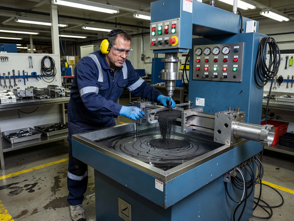
2.5 Head Shot (Direct Contact) Method
The head shot technique clamps the part between two conductive contact plates (head and tail stock in a stationary wet bench unit). High current passes directly through the part lengthwise, generating a circular magnetic field concentric around the part — ideal for detecting longitudinal cracks.
The current requirement for head shot magnetization follows the ratio of approximately 300–800 amps per inch (25 mm) of part diameter, depending on material and specification.
Central Conductor Variation: For hollow or ring-shaped parts (bearings, gears, bushings), a copper conductor is threaded through the center bore. Current flows through the conductor (not through the part itself), creating a circular magnetic field on both the internal and external surfaces of the part. This avoids the risk of passing damaging currents through precision-machined parts.
Advantages: Produces a strong, uniform circular field. Fast and efficient in stationary bench units designed for production inspection. Capable of inspecting complex shapes.
Disadvantages: Risk of burning at contact points. Unsuitable for parts that could be damaged by current flow (finished machined surfaces, sensitive electronic assemblies). Requires large current for large parts.
2.6 Induced Current Method
The induced current method uses the principle of electromagnetic induction to generate eddy currents in a conductive part without direct electrical contact. The part acts as the secondary winding of a transformer. This method is restricted to circular parts forming a closed-loop electrical path (rings, washers, bearings) with no radial cuts or deep notches that would interrupt current flow.
Advantages: No electrical contact with the part, eliminating any risk of arcing or burn damage. Ideal for finished, precision-machined components.
Disadvantages: Only works on closed-loop geometries. Complex setup compared to other methods. Less common and not available on all MT equipment.
3. Wet vs Dry Magnetic Particles
The selection between wet and dry magnetic particles significantly affects detection sensitivity, application efficiency, and the types of defects that can be reliably identified. Each method has distinct characteristics defined by particle size, carrier medium, application technique, and sensitivity level.
3.1 Dry Particle Method
Dry particles are fine iron powder formulations, typically manufactured from precipitated soft iron. Particle sizes range from approximately 50 to 150 μm (significantly coarser than wet particles). The particles are applied by dusting using a powder bulb, manual sprinkling, or spray gun. Excess powder is gently removed with a low-pressure air stream to reveal particle indications at defect locations.
Characteristics
Dry Particle Method
Particle size
50–150 μm (coarse)
Carrier
None (dry powder)
Application
Powder bulb, sprinkler, spray gun
Surface requirements
Excellent on rough surfaces
Subsurface detection
Superior (larger particles bridge subsurface void gaps)
Temperature range
Works at extreme temperatures (hot castings up to 600°F/315°C)
Sensitivity (relative)
Baseline (×1)
Wind sensitivity
Poor — powder blown away in outdoor windy conditions
When to use dry particles: Rough castings and forgings where surface irregularities would trap liquid carriers. High-temperature parts inspected immediately after processing. Subsurface detection priority (larger dry particles are more sensitive to broad, diffuse leakage fields from subsurface defects). Outdoor field inspections in calm conditions. Environments where liquid carriers are prohibited (flammable atmospheres, contamination-sensitive areas).
3.2 Wet Particle Method
Wet particles are finely divided iron particles (typically 1–10 μm in size) suspended in a liquid carrier fluid. The particles are coated with visible dyes (red, black) or fluorescent dyes for enhanced contrast. Two carrier fluid types are used:
Oil-based carriers — Traditional petroleum distillate carriers providing excellent wetting properties and low evaporation rates. The primary disadvantage is flammability, requiring careful handling and storage. Flash point must be above 93°C (200°F) per ASTM E709.
Water-based carriers — Non-flammable, economical, and environmentally preferred. Water-based baths require careful formulation including wetting agents (to reduce surface tension), corrosion inhibitors (to prevent rusting of the part under inspection), and antifoaming agents. Water bath concentration must be monitored with a refractometer.
Particle concentration in wet baths is critical and must be verified using a centrifuge tube settling test (pearl test). Acceptable concentration is typically 0.1–0.4 mL of settled particles per 100 mL of bath sample. Too few particles reduces detection sensitivity; too many particles creates excessive background buildup that masks indications.
Characteristics
Wet Particle Method
Particle size
1–10 μm (fine)
Carrier
Oil or water
Application
Flow-through, spray, immersion
Surface requirements
Smooth, clean surfaces preferred
Subsurface detection
Moderate
Temperature range
Limited by carrier fluid (typically 40–140°F / 5–60°C)
Sensitivity (visible)
×2–3 relative to dry
Sensitivity (fluorescent)
×5–10 relative to dry
When to use wet particles: Production-line inspection in stationary wet benches. Smooth surfaces requiring high sensitivity. Fluorescent inspection requiring the highest sensitivity level. High-volume repetitive inspection of similar parts. Critical safety components (aerospace, automotive, nuclear).
4. Visible vs Fluorescent Magnetic Particles
The choice between visible and fluorescent particles determines the lighting environment, equipment requirements, and practical detection sensitivity.
4.1 Visible (Non-Fluorescent) Particles
Visible particles are iron particles coated with colored pigments — commonly red, black, gray, or yellow — to contrast against the part surface. For optimal contrast, a white contrast paint is typically applied to the part surface before inspection, providing a uniform light-colored background against which dark particle indications are clearly visible.
Lighting requirements: Minimum 1000 lux (approximately 100 foot-candles) of white light measured at the inspection surface. This is a relatively high illumination level requiring strong work lights for indoor inspections. Outdoor inspections during daylight hours can typically achieve this level.
Sensitivity: Reliable detection of moderate to large surface cracks. Tight cracks (less than approximately 1 μm opening width) may not produce sufficiently distinct indications. The contrast between white background paint and dark particle buildup provides good visual acuity for typical defect sizes.
Advantages: No UV light equipment required. Operates in bright outdoor environments without darkening. Lower overall equipment cost. Simpler setup and training requirements. Easier documentation under normal lighting.
Disadvantages: Lower inherent contrast compared to fluorescent particles (the human eye is less sensitive to subtle brightness differences in the photopic range than to the high-contrast glow of fluorescent indications against a dark background). White contrast paint adds application and removal time. Small or faint indications may be missed.
4.2 Fluorescent Particles
Fluorescent particles are iron particles coated with fluorescent dyes that absorb UV-A (black light, long-wave ultraviolet) in the 320–395 nm wavelength range (typically peaking at 365 nm) and emit visible light in the yellow-green spectrum at approximately 555 nm — the wavelength to which the human eye has maximum photopic sensitivity.
Lighting requirements:
UV-A intensity: Minimum 1000 μW/cm² at the inspection surface, verified using a calibrated UV-A radiometer (not a general-purpose light meter).
Ambient white light: Maximum 20 lux (2 foot-candles) — essentially a darkened environment. Higher ambient light levels wash out the fluorescent indication contrast.
Warm-up time: Mercury vapor UV lamps require 5–10 minutes warm-up; LED UV lamps reach full intensity instantly.
Dark adaptation: Inspectors should allow 5–10 minutes in the darkened inspection area before beginning fluorescent inspection to allow the eyes to adapt to low-light conditions.
Sensitivity: The highest sensitivity of any MT method. Fluorescent indications appear as bright yellow-green glowing accumulations against a very dark background, providing the maximum possible contrast to the human visual system. Fine, tight cracks with openings smaller than 1 μm can be reliably detected.
Advantages:5–10 times more sensitive than dry visible particles. Excellent contrast makes indications unmistakable — even very small accumulations are visible. Ideal for high-speed production inspection where the inspector scans large surface areas quickly. Yellow-green emission at the peak of human eye sensitivity maximizes detection probability.
Disadvantages: Requires darkened environment (difficult or impossible for outdoor field inspections in daylight). Requires UV lamps, UV protective eyewear, and PPE. Dark adaptation time reduces productivity. Higher initial equipment cost. UV lamps require periodic intensity verification.
5. Procedure and Standards (ASTM E709 and ASTM E1444)
Magnetic Particle Testing is governed by a comprehensive framework of national and international standards that define equipment requirements, procedural steps, calibration intervals, and personnel qualification. The two most important ASTM standards for MT are E709 and E1444.
5.1 ASTM E709 — Standard Guide for Magnetic Particle Testing
ASTM E709 is the comprehensive “mother standard” for MT, covering all aspects of the method. It is a guide (not a practice) — meaning it provides detailed information and recommendations but does not specify minimum mandatory requirements.
Scope: Covers both dry and wet particle techniques. Applicable to raw materials (blooms, billets, ingots), semi-finished products (forgings, castings, extrusions), welds, and in-service components of any size, shape, or ferromagnetic material.
Key requirements and recommendations per ASTM E709:
Surface preparation: Surfaces must be clean, dry, and free of oil, grease, rust, scale, paint, and other contaminants that could mask indications or interfere with particle mobility.
Magnetization: Two perpendicular magnetization directions are required. Multiple methods may be needed for complex geometries.
Field strength verification: Must be performed using an ASTM field indicator (pie gauge), Hall-effect probe, or quantitative quality indicator (QQI) shims. The field indicator is a small cross-shaped piece of low-carbon steel with artificial flaws in its arms, placed on the part and observed for particle attraction.
Particle selection: Particle type, size, and color must be selected based on material, surface condition, defect type sought, and lighting conditions.
Lighting: Minimum 1000 lux for visible particles; maximum 20 lux ambient white light with minimum 1000 μW/cm² UV-A for fluorescent particles.
Personnel qualification: Per ASNT SNT-TC-1A, ANSI CP-189, or NAS 410.
Demagnetization: Required when residual magnetism could interfere with subsequent operations.
Reporting: Documentation must include procedure identification, part description, results (location, type, size of indications), and inspector identification.
Acceptance criteria: ASTM E709 does not specify acceptance/rejection criteria. These are defined by the contracting parties, engineering design specification, or applicable code.
5.2 ASTM E1444 — Standard Practice for Magnetic Particle Testing
ASTM E1444 is a practice (not a guide) specifying minimum mandatory requirements for MT, specifically written for aerospace applications. It replaced the former military standard MIL-STD-1949 and is referenced by NAS 410 for personnel certification.
Key differences from ASTM E709 (stricter requirements):
Requirement
ASTM E709 (Guide)
ASTM E1444 (Aerospace Practice)
Particle concentration
Recommends verification
Mandates centrifuge tube settling test at specified intervals
UV-A intensity
Recommends minimum 1000 μW/cm²
Mandates minimum 1000 μW/cm² with specific calibration frequency
Ambient light
Recommends maximum 20 lux
Mandates maximum 20 lux with verification
White light for visible
Recommends minimum 1000 lux
Mandates minimum 1000 lux with verification
Calibration frequency
Recommends intervals
Specifies exact calibration intervals
Demagnetization limits
Recommends as needed
Specifies ≤3 Gauss for critical components
Personnel certification
Per SNT-TC-1A
Per NAS 410 (aerospace)
5.3 Calibration and Performance Verification
Routine calibration checks required by both standards include:
Yoke lift test: Daily verification that the yoke can lift the specified weight. AC yoke: 10 lb (4.5 kg). DC yoke: 40–50 lb (18–22.7 kg) depending on pole spacing.
UV-A intensity check: Daily verification using a calibrated UV-A radiometer. Minimum 1000 μW/cm² at the inspection surface.
White light intensity check: Daily verification using a calibrated light meter. Minimum 1000 lux for visible particle inspection.
Bath concentration check: Settling test using a centrifuge tube (pearl test). Acceptable range typically 0.1–0.4 mL settled particles per 100 mL sample. Frequency specified by procedure.
Field indicator check: Verification that the magnetic field is adequate using an ASTM pie gauge or QQI shim. Performed daily or with each new part configuration.
5.4 Standard MT Procedure
A standardized MT procedure following ASTM E709 or equivalent generally includes these steps:
Pre-cleaning — Remove all contaminants (grease, oil, rust, scale, paint, coatings) from the inspection surface using solvents, detergents, abrasive blasting, or grinding.
Contrast coating — Apply white contrast paint (for visible particles) or ensure surface cleanliness (for fluorescent particles).
Magnetization — Apply the magnetizing force using the selected method and current type. The part must be magnetized in two perpendicular directions sequentially.
Particle application — Apply magnetic particles while the magnetizing force is maintained (continuous method). The continuous method is preferred over the residual method because it provides the strongest particle attraction.
Examination — Inspect the surface under the required lighting conditions. Examine for particle accumulations forming indications.
Interpretation — Evaluate indications as relevant (caused by a discontinuity) or non-relevant (caused by geometry changes, magnetic writing, or other non-defect conditions).
Documentation — Record indication location, orientation, size, type, and any measurements. Photographs should be taken.
Demagnetization — Perform if required by the specification or subsequent operations.
Post-cleaning — Remove residual particles and contrast coating from the part.
6. Detection Capabilities
6.1 Detectable Defect Types
MT detects a wide range of metallurgical and fabrication defects when they are at or near the surface of ferromagnetic materials:
Defect Type
Description
Typical Origin
Detectability
Fatigue cracks
Progressive crack growth from cyclic loading
Service loading, vibration
Excellent — primary MT application
Quench cracks
Cracks from thermal stress during heat treatment
Manufacturing — heat treatment
Excellent — typically surface-connected
Grinding cracks
Shallow, fine crack networks from abrasive grinding
Manufacturing — improper grinding
Excellent — fine, shallow, surface-connected
Stress-corrosion cracks
Cracking from tensile stress and corrosive environment
Service environment
Excellent — typically surface-initiated
Forging laps
Folded metal on surface from forging operations
Manufacturing — forging
Good — surface or near-surface
Rolling seams
Longitudinal cracks from rolling operations
Manufacturing — rolling
Good — elongated, surface-connected
Cold shuts
Discontinuities from incomplete fusion in casting
Manufacturing — casting
Good — surface-open
Weld toe cracks
Cracks initiating at weld toe, propagating into base metal
Welding — service loading
Excellent — surface-connected
Weld root cracks
Cracks in the weld root (underside)
Welding — restraint
Excellent — if accessible
Underbead cracking
Hydrogen-induced cracking in HAZ
Welding — hydrogen embrittlement
Good — often subsurface
Lack of fusion
Unbonded weld interfaces
Welding — improper technique
Good — if surface or near-surface
Slag inclusions
Trapped non-metallic slag
Welding — inadequate cleaning
Fair — depends on size and depth
6.2 Minimum Detectable Flaw Size
The minimum detectable flaw size depends on multiple variables including crack width (tightness), crack depth, orientation relative to the magnetic field, particle type, lighting, surface condition, and inspector skill.
Wet fluorescent method: Reliably detects cracks as small as 1–2 mm (0.04–0.08 in) in length. Under ideal laboratory conditions, cracks as small as 0.5 mm can be detected.
Wet visible method: Reliably detects cracks approximately 2–4 mm (0.08–0.16 in) in length.
Dry particle method: Typically detects cracks approximately 3–6 mm (0.12–0.25 in) in length.
The probability of detection (POD) for MT follows typical NDT POD curves. At the 90% probability level with 95% confidence (90/95 POD), the detectable crack size for wet fluorescent MT is approximately 2.0 mm for most practical inspection scenarios.
6.3 Surface vs Subsurface Detection
MT detects surface-breaking discontinuities with high reliability and, under specific conditions, can detect near-subsurface discontinuities up to approximately 6 mm (¼ inch) below the surface.
Depth
Detectability
Indication Characteristics
Surface (open)
Excellent
Sharp, distinct, tightly held particle pattern
Subsurface 0–2 mm
Good
Broader pattern, particles moderately held
Subsurface 2–6 mm
Fair — requires DC/HWDC
Diffuse, fuzzy pattern; particles loosely held
Beyond 6 mm
Poor to not detectable
Insufficient leakage flux reaches surface
Current type effect on subsurface detection: AC penetration is limited to approximately 0.1–1 mm due to the skin effect — essentially surface-only detection. DC and HWDC penetrate the full cross-section and are required for any subsurface detection capability. HWDC provides the deepest penetration and, due to the pulsating nature of half-wave rectified current, imparts mechanical vibration to the particles, enhancing mobility and sensitivity.
Subsurface indication characteristics: Subsurface defect indications appear broader, more diffuse, and less distinct than surface indications. The particle pattern may appear “fuzzy” or indistinct at the edges. Particles are loosely held by the weaker leakage field and may be partially removed by a gentle air stream.
7. Demagnetization
7.1 Why Demagnetization Is Required
After MT inspection, residual magnetism remains in the part. The magnitude of residual magnetism depends on the material’s retentivity, the applied field strength, and the magnetization method used. Residual magnetism can cause significant problems in subsequent operations:
Interference with welding — Magnetic arc blow causes the welding arc to wander erratically, producing poor weld quality, arc strikes, and slag inclusions.
Interference with machining — Chips, turnings, and cutting debris are attracted to the magnetized part, causing tool wear, surface scratching, and difficulty in cleaning.
Interference with sensitive instruments — Navigation equipment (compasses, magnetometers), electronic sensors, and aircraft instruments can be adversely affected by nearby magnetized components.
Interference with subsequent NDT — Eddy current testing, magnetic flux leakage testing, and other electromagnetic methods are affected by residual magnetism.
Ferrous debris attraction — In bearing assemblies, engines, and hydraulic systems, magnetized components attract ferrous wear particles that accelerate component wear.
Personnel safety — Large magnetized parts can violently attract ferrous tools, creating pinching and impact hazards.
7.2 Residual Magnetism Limits
Application
Maximum Residual Magnetism
Non-critical industrial components
≤5 Gauss
Aerospace and critical components (per ASTM E1444)
≤3 Gauss
Weld joint preparation (before welding)
5–40 Gauss (varies by process)
Electron beam welding
<3 Gauss
Bearing surfaces
<3 Gauss
Navigation equipment proximity
<2 Gauss (typically)
7.3 Demagnetization Methods
AC Decay Method (Most Common): The part is placed in an AC solenoid coil, or an AC yoke is passed over its surface. AC current at the maximum available amplitude is applied, then gradually reduced to zero over several seconds. Each decreasing cycle reduces domain alignment until the domains return to random orientation. For large parts, the pull-through method is used: the part is drawn through an AC coil and slowly withdrawn while current is flowing. The increasing distance from the coil produces a decreasing field strength without requiring variable current control. AC demagnetization is effective for surface demagnetization but limited in depth due to the skin effect.
Reversing DC Method: DC current with alternating polarity is applied, with each successive reversal having a lower amplitude than the previous one. The process continues until the amplitude reaches zero. This method penetrates the full cross-section of thick parts and is effective for components that cannot be demagnetized by AC methods alone.
Thermal Demagnetization: The part is heated above its Curie temperature (770°C/1418°F for iron), at which point ferromagnetic properties are lost. As the part cools in a non-magnetized environment (zero applied magnetic field), no residual magnetism remains. This method is generally impractical for large structures and risks altering material properties and causing distortion.
Knockdown Method: A magnetic field of precisely controlled opposite polarity and magnitude is applied to cancel the residual magnetism. This is a targeted technique requiring measurement of the residual field before application.
7.4 Verification of Demagnetization
Residual magnetism is verified using a gauss meter with a Hall-effect probe. The probe is placed at multiple locations on the part surface, and the maximum field reading is recorded. Industry practice requires verifying at multiple locations and in multiple orientations. For critical components, verification is performed after all handling and cleaning operations to ensure no re-magnetization has occurred.
8. Magnetic Particle Testing for Steel Bridge Members
8.1 Regulatory Framework
The Federal Highway Administration (FHWA) mandates periodic inspection of steel bridges in the United States under the National Bridge Inspection Standards (NBIS) . A critical subset of steel bridge members — fracture-critical members (FCMs) — require inspection every 24 months using NDT methods including MT.
Fracture-critical members are defined by the FHWA as steel tension members whose failure would likely cause the entire bridge to collapse. These include: main truss tension members, steel girders in tension zones, floor beams, box girder tension flanges, steel hangers, pin-and-hanger assemblies, suspension cables, and tie members of tied-arch bridges.
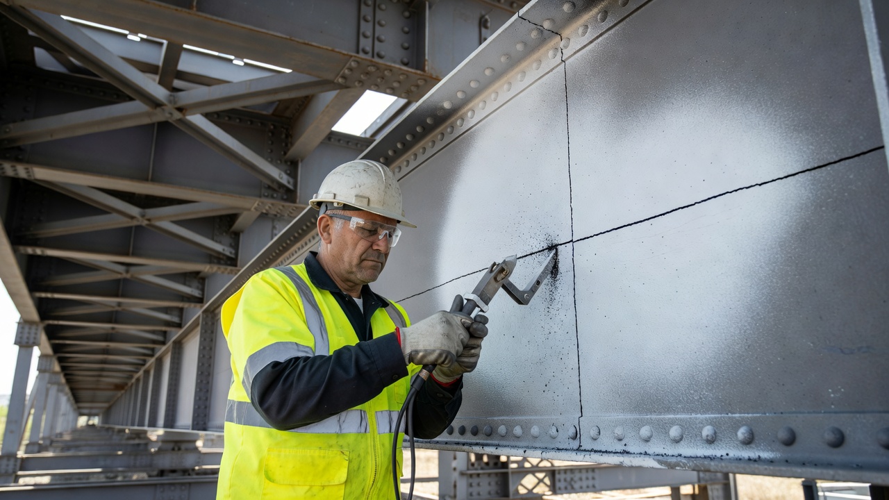
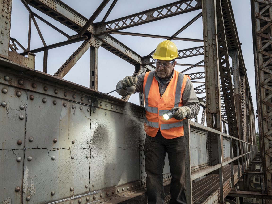
8.2 Inspection Protocol for Steel Bridges
The typical MT inspection procedure for steel bridge members follows these steps:
Paint removal — At suspect areas (weld toes, weld ends, stiffener-to-web connections, cover plate ends), paint is removed by grinding, needle gun, or abrasive blasting. The removal area must extend at least 50 mm (2 inches) beyond the suspected defect zone.
Surface preparation — Ground surfaces are smoothed to prevent false particle indications from surface roughness.
Contrast coating — White contrast paint is applied to provide a uniform background for visible particle inspection.
Magnetization — An AC yoke is used, positioned first parallel to the weld axis (to detect transverse cracks) and then perpendicular to the weld axis (to detect longitudinal cracks). The yoke is systematically moved across the prepared area with overlapping pole placements.
Particle application — Wet visible magnetic particles are applied by spray or aerosol can while the magnetizing force is maintained.
Inspection — Under minimum 1000 lux white light, the inspector examines the surface for particle buildups forming indications.
Documentation — All relevant indications are measured, photographed, and reported with location reference to bridge stationing and member identification.
8.3 Fatigue Crack Locations on Steel Bridges
Fatigue cracks in welded steel bridges occur at predictable locations identified through decades of research by the FHWA, Transportation Research Board (TRB), and state DOTs:
Weld toes of stiffener-to-web and stiffener-to-flange fillet welds — the most common fatigue crack location
Welded cover plate ends — where the cover plate terminates on the girder flange
Flange transition welds — at changes in flange width or thickness
Distortion-induced fatigue at diaphragm connection plates — caused by out-of-plane distortion of girder webs
Pin-and-hanger assemblies — at pin holes and weld attachments
Floor beam-to-girder connections — at welded or bolted connections
8.4 Acceptance Criteria per AWS D1.5
The AWS D1.5 Bridge Welding Code (Chapter 6 — Inspection) defines acceptance criteria for MT indications on bridge welds:
Cracks and crack-like linear indications — Not acceptable regardless of size
Rounded indications — Must be evaluated; indications > 1/16 in (1.6 mm) require disposition
Linear indications — Indications > 1/8 in (3.2 mm) are typically rejectable per most DOT criteria
Disposition — Rejectable indications require repair by grinding (if within weld reinforcement limits) or removal and re-welding
9. Magnetic Particle Testing for Weld Inspection
9.1 Weld Defects Detected by MT
Welds in ferromagnetic materials are among the most common applications of MT. The method detects virtually all types of surface and near-surface weld discontinuities:
Weld Defect
Description
Location
Typical Cause
Toe crack
Crack at weld toe propagating into base metal or weld
Weld toe — fusion line
High restraint, hydrogen, fatigue
Root crack
Crack in the weld root pass
Weld root (underside)
High restraint, inadequate penetration
Crater crack
Star-shaped or longitudinal crack at weld termination
End of weld bead
Improper crater fill, rapid solidification
Centerline crack
Crack running along weld centerline
Weld center
Weld metal shrinkage, incorrect filler
Transverse crack
Crack perpendicular to weld axis
Across weld face
High restraint, hydrogen embrittlement
Underbead crack
Hydrogen-induced crack in heat-affected zone
Adjacent to weld — HAZ
Hydrogen from welding consumables, moisture
Hot crack (solidification crack)
Crack formed during solidification
Weld metal
Impurities, high sulfur content
Cold crack (delayed crack)
Cracks forming hours to days after welding
HAZ and weld metal
Hydrogen diffusion, residual stress
Lack of fusion
Unbonded interface between weld and base
Weld fusion zone
Insufficient heat, improper technique
Surface porosity
Gas pockets open to surface
Weld face
Moisture, contamination, improper shielding
9.2 Timing of Weld Inspection
Pre-weld MT: Inspection of base material edges, weld bevels, and surfaces for pre-existing cracks, laminations, or seams before initiating welding. Tack welds should also be inspected before final welding.
Post-weld MT: After welding and cooling to ambient temperature, immediate inspection for hot cracks and other surface defects. For hydrogen-sensitive materials (high-strength steels, thick sections > 25 mm, restrained joints), a delayed inspection 24–48 hours after welding is mandatory to allow time for hydrogen-induced cracking to develop.
Interpass MT: For critical multi-pass welds, MT may be performed between weld passes to detect cracking before subsequent passes cover the defect.
9.3 Typical Weld MT Procedure
Clean the weld area — Remove slag, spatter, scale, and weld smoke residues within approximately 75 mm (3 inches) of the weld toe on each side.
Contrast coat — Apply white contrast paint to the weld and adjacent base metal.
First magnetization direction — Position yoke with poles parallel to the weld axis (field perpendicular to weld). This detects longitudinal weld defects (centerline cracks, lack of fusion, root cracks).
First particle application — Apply wet visible particles along the full length of the prepared area while maintaining magnetization.
First inspection — Examine for indications. Document findings.
Second magnetization direction — Rotate yoke 90° so poles are perpendicular to the weld axis (field parallel to weld). This detects transverse weld defects (transverse cracks, toe cracks).
Second particle application — Reapply particles in the perpendicular orientation.
Second inspection — Examine for indications. Document findings.
Demagnetization — If required by specification.
Surface restoration — Remove contrast paint and residual particles.
9.4 Weld MT Standards
Standard
Application
AWS D1.1
Structural Welding Code — Steel (buildings, general structures)
AWS D1.5
Bridge Welding Code (highway bridges)
ASME Section V Article 7
Boiler and Pressure Vessel Code — MT requirements
ASME Section VIII Div. 1
Pressure Vessel construction
API 1104
Pipeline welding and inspection
API 650
Welded steel storage tanks
10. Magnetic Particle Testing vs Dye Penetrant Testing
MT and dye penetrant testing (PT) are the two primary surface NDT methods. While both detect surface-breaking defects, they differ fundamentally in applicable materials, defect detection physics, sensitivity, and procedural requirements.
10.1 Direct Comparison
Parameter
Magnetic Particle (MT)
Dye Penetrant (PT)
Applicable materials
Ferromagnetic only (Fe, Ni, Co alloys)
Any non-porous material (metals, plastics, ceramics, glass, composites)
Defects detected
Surface and near-subsurface (up to ~6 mm)
Surface-breaking only
Subsurface detection
Yes — up to ~6 mm with DC/HWDC
No — cannot detect subsurface defects
Minimum detectable width
Dependent on leakage field; ~1–2 mm crack length (fluorescent)
~150 nm crack opening width
Through-coating detection
Yes — can detect through thin non-conductive coatings (~1–2 mil/25–50 μm paint)
No — surface must be clean and bare
Inspection speed
Immediate results — seconds per application
Slower — 10–30 minute dwell time required
Surface preparation
Moderate — cleaning required but through-coating capability reduces prep
Critical — surface must be clean, dry, free of all contaminants
Portability
Good — yokes, prods, power packs
Excellent — aerosol cans
Equipment cost
Higher — $500–$50,000 (yokes, benches, UV lamps)
Lower — $50–$500 (spray cans, UV light)
Skill level required
Moderate to high — magnetic field direction, current type, interpretation
Lower — simpler procedure
Post-cleaning
Minimal — blow off powder
Required — remove penetrant and developer
Demagnetization
Often required
Not required
False indications
Less common — magnetic field physics is deterministic
More common — entrapped penetrant, bleed-out
Permanent record
Photographs
Photographs
10.2 Decision Factors
Choose MT when:
The material is ferromagnetic (steel, iron, nickel, cobalt)
Subsurface detection capability is needed (up to 6 mm depth)
Speed is critical — MT provides immediate results without dwell time
The surface has light coatings that would be removed for PT
Higher reliability for crack detection is required on ferromagnetic alloys
Inspection area is in a production-line environment with high throughput
Choose PT when:
The material is non-ferromagnetic (aluminum, stainless steel, titanium, copper alloys, plastics, ceramics, glass)
Only surface-breaking defects are of concern
Portability and low equipment cost are primary considerations
Part geometry is complex and MT magnetization would be difficult (threads, sharp corners, deep cavities)
Lower operator skill level is available
Inspection is performed on non-magnetic weldments (aluminum structures, stainless steel piping)
10.3 Practical Example: Steel Bridge Inspection
For steel bridge member inspection, MT is consistently preferred over PT because:
Steel is ferromagnetic — MT is directly applicable
Fatigue cracks in bridge members are frequently tight and may initiate slightly below the surface before breaking through — MT detects these subsurface crack origins
Bridge welds may have thin paint coatings that do not need full removal for MT
The speed of MT (no dwell time) is advantageous for field inspections with limited lane closure time
MT is less affected by surface roughness and field conditions
For aluminum bridge components (sign structures, pedestrian bridges, light poles), PT must be used because aluminum is non-ferromagnetic and cannot be magnetized.
11. Aviation and Aerospace MT Standards
11.1 Regulatory Framework
Aviation MT is governed by a multi-layered regulatory framework that integrates international standards, national aviation authorities, and industry specifications.
Organization
Standard/Regulation
Relevance
FAA
AC 65-31B / 14 CFR Part 43
NDT personnel training and qualification; maintenance practices
EASA
Part 145 / Annex II
European aviation maintenance requirements
SAE International
NAS 410 (formerly ASNT-TC-1A-based)
Primary aerospace NDT personnel certification standard
ASTM
ASTM E1444
Standard Practice for MT — aerospace-specific requirements
ASTM
ASTM E709
Standard Guide for MT (reference document)
ICAO
Annex 6 (Operation of Aircraft), Annex 8 (Airworthiness)
International framework for aircraft maintenance and NDT
ISO
ISO 9712
International NDT personnel certification
11.2 Aerospace-Specific Requirements
Aerospace MT is predominantly wet fluorescent — the highest sensitivity method — applied to critical safety components including:
Aircraft steel parts only (aluminum, titanium, and composites are non-ferromagnetic)
Key requirements per NAS 410 / ASTM E1444:
Personnel must be certified to NAS 410 or equivalent
Category II (Level II) or above required to independently perform and interpret MT
Mandatory recertification at intervals (typically 5 years)
Annual eye examination — near-vision acuity (Jaeger J-2 or equivalent at 30 cm), color vision discrimination (Ishihara or Farnsworth D-15), and contrast sensitivity
Dark adaptation — minimum 5 minutes before fluorescent inspection
Part-specific written procedures approved by the responsible NDT Level III
Demagnetization to ≤3 Gauss for flight-critical components
Documented bath concentration verification at specified intervals
11.3 ICAO Context
While ICAO does not issue detailed MT procedures, the framework established by ICAO Annex 6 (Operation of Aircraft) and Annex 8 (Airworthiness) requires that aircraft maintenance and inspection — including NDT — be performed in accordance with approved standards. States of design and registry must ensure that maintenance organizations comply with NADCAP (National Aerospace and Defense Contractors Accreditation Program) or equivalent accreditation for NDT services.
Magnetic Particle Testing remains one of the most reliable, cost-effective, and widely applied NDT methods for ferromagnetic structures worldwide. Its combination of surface and near-subsurface detection capability, immediate results, portability, and proven effectiveness for crack detection on steel bridges, welds, and aerospace components makes it an indispensable tool for structural integrity assessment. When applied by properly certified personnel following established standards (ASTM E709, ASTM E1444, ASME, AWS), MT provides high probability of detection for the defects that most threaten the safety of steel structures.
Frequently Asked Questions
Magnetic Particle Testing (MT) is a non-destructive testing method that detects surface and near-surface discontinuities in ferromagnetic materials (iron, steel, nickel, cobalt, and their alloys). The method works by introducing a magnetic field into the component. In a defect-free part, magnetic flux lines flow uniformly through the material. When a discontinuity such as a crack, lap, or seam is present, it creates an abrupt change in magnetic reluctance (resistance to magnetic flux). Since air has much lower magnetic permeability than ferromagnetic material, flux lines cannot easily pass through the air gap at the discontinuity. Instead, the flux lines leak out of the part at the discontinuity, creating a magnetic leakage field. Finely divided ferromagnetic particles applied to the surface are attracted to these leakage fields, forming visible particle buildups (indications) that reveal the size, shape, and location of the discontinuity. The inspection requires magnetization in two mutually perpendicular directions to detect flaws at all orientations.
MT detects a wide range of surface and near-surface defects including fatigue cracks, quench cracks, grinding cracks, stress-corrosion cracks, forging laps, rolling seams, cold shuts, non-metallic inclusions, weld defects (toe cracks, root cracks, crater cracks, centerline cracks, underbead cracking, lack of fusion, porosity), and hydrogen-induced cracking. The method excels at detecting fine, tight surface cracks that may be invisible to the naked eye. With wet fluorescent particles, MT can reliably detect cracks as small as 1-2 mm in length. Subsurface defects up to approximately 6 mm (¼ inch) below the surface can be detected using DC or half-wave DC current. However, MT only works on ferromagnetic materials and cannot detect subsurface defects deeper than 6 mm.
Dry particle testing uses fine iron powder in the 50-150 μm size range, applied by dusting or sprinkling onto the surface. Dry particles are excellent for rough surfaces like castings and forgings, work well at extreme temperatures, and are ideal for outdoor field inspections. However, they have lower sensitivity to fine, tight cracks. Wet particle testing uses iron particles suspended in a liquid carrier fluid (oil or water-based), with particle sizes of 1-10 μm. Wet particles provide the highest sensitivity — especially fluorescent wet particles — and offer uniform, even coverage ideal for production-line inspection and smooth surfaces. Wet fluorescent MT is approximately 5-10 times more sensitive than dry visible MT. The trade-off is that wet methods require clean surfaces, careful bath concentration monitoring (0.1-0.4 mL per 100 mL), and proper handling of carrier fluids.
The five primary magnetization methods are: (1) Yoke method — a handheld U-shaped electromagnet placed on the part surface, ideal for field weld inspection and portable use. AC yokes detect surface cracks effectively and require minimal demagnetization. DC yokes provide deeper penetration for subsurface detection. (2) Prod method — two handheld copper electrodes pressed against the part to pass current directly through it, generating a circular magnetic field. Best for heavy castings and thick sections but carries arcing risk. (3) Coil method — the part is placed inside a solenoid coil that induces longitudinal magnetization along the part length. Efficient for cylindrical parts in production settings. (4) Head shot — the part is clamped between conductive plates and current passes through it, producing a circular field ideal for detecting longitudinal cracks. (5) Central conductor — a copper conductor is passed through hollow parts, carrying current to create a circular field on internal and external surfaces with no risk of arcing on the part.
The primary MT standards are ASTM E709 (Standard Guide for Magnetic Particle Testing), which is the comprehensive 'mother standard' covering all aspects of the method, and ASTM E1444 (Standard Practice for Magnetic Particle Testing), which is the stricter aerospace-specific practice that replaced MIL-STD-1949. ASME Section V Article 7 covers MT for pressure vessel and boiler code applications. AWS D1.1 and D1.5 govern MT for structural welding and bridge welding respectively. For aerospace, NAS 410 governs personnel certification. ISO 9934-1 is the international standard. Additional standards include API 1104 (pipeline welding), API 650 (storage tanks), and various military and industry-specific specifications. Neither ASTM E709 nor E1444 specifies acceptance/rejection criteria — these are defined by the contracting parties or applicable code.
MT and PT both detect surface-breaking defects, but they differ fundamentally. MT only works on ferromagnetic materials (steel, iron, nickel, cobalt), while PT works on any non-porous material including aluminum, stainless steel, plastics, ceramics, and glass. MT detects both surface and near-subsurface defects (up to ~6 mm depth), while PT detects surface-breaking defects only. MT provides immediate results with no dwell time, while PT requires 10-30 minutes of dwell time. MT can detect through thin non-conductive coatings (~1-2 mil paint), while PT requires clean, bare surfaces. MT generally has higher sensitivity for crack detection on ferromagnetic materials. Equipment cost for MT is higher (yokes, power packs, UV lamps, wet benches) versus PT (spray cans, UV light). MT often requires post-inspection demagnetization, while PT does not. For ferromagnetic materials, MT is typically preferred over PT because of its subsurface detection capability, speed, and higher reliability.
A typical MT procedure follows these steps: (1) Clean the surface thoroughly — remove all grease, oil, rust, scale, paint, and other contaminants. (2) Apply white contrast paint if using visible particles to improve background contrast. (3) Select the appropriate magnetization method (yoke, prod, coil, etc.) and current type (AC for surface, DC/HWDC for subsurface). (4) Magnetize the part in one direction. (5) Apply magnetic particles while the magnetizing force is maintained (continuous method). (6) Inspect the surface under proper lighting — minimum 1000 lux white light for visible particles, or maximum 20 lux ambient with minimum 1000 μW/cm² UV-A for fluorescent particles. (7) Repeat magnetization in the perpendicular direction to ensure all defect orientations are detected. (8) Document all relevant indications with photographs and measurements. (9) Demagnetize if required. (10) Clean the part surface. The entire process is rapid — typically minutes per inspection area.
Demagnetization is required when residual magnetism could interfere with subsequent operations or performance. Common reasons include: welding operations (magnetic arc blow), machining (chips attracted to surfaces), operation of sensitive electronic instruments or navigation equipment, subsequent NDT methods (especially eddy current testing), bearing surfaces (ferrous wear debris attraction), and aerospace components (strict limits typically ≤3 Gauss). General industrial limits are typically ≤5 Gauss residual magnetism. Demagnetization is most commonly performed using the AC decay method — applying an AC field and gradually reducing amplitude to zero, or pulling the part through an AC coil. For thick parts requiring deep penetration, reversing DC demagnetization is used. Thermal demagnetization (heating above the Curie temperature, ~770°C for iron) provides complete demagnetization but is impractical for most parts. Verification is performed using a gauss meter (Hall-effect probe).
The Federal Highway Administration (FHWA) National Bridge Inspection Standards (NBIS) require inspection of fracture-critical members (FCMs) on steel bridges every 24 months. FCMs are steel tension members whose failure would cause bridge collapse — including main girders, truss tension members, box girders, steel hangers, pin-and-hanger assemblies, and floor beams. MT is the primary NDT method for detecting fatigue cracks in these members. The typical procedure involves: paint removal at weld toes and suspect areas (by grinding or abrasive blasting), application of white contrast paint, magnetization using an AC yoke in two perpendicular directions, application of wet visible magnetic particles, and inspection under adequate lighting. Common fatigue crack locations include weld toes of stiffener-to-web fillet welds, welded cover plate ends, flange transition welds, and distortion-induced fatigue at diaphragm connection plates. AWS D1.5 (Bridge Welding Code) specifies acceptance criteria — cracks and crack-like linear indications are rejectable.
MT personnel certification follows ASNT SNT-TC-1A (Recommended Practice for Nondestructive Testing Personnel), NAS 410 (aerospace industry standard), or ISO 9712 (international standard). Three levels of certification exist. Level I performs specific MT operations under supervision. Level II sets up equipment, conducts tests, interprets results, and reports findings independently. Level III develops procedures, trains personnel, and manages NDT programs. For aerospace MT per ASTM E1444 and NAS 410, personnel must have annual eye examinations (near-vision acuity, color vision discrimination, and contrast sensitivity). Certification requires documented training hours (typically 40 hours classroom for Level I, additional 40 hours for Level II), practical examinations, and written exams. Recertification is required at intervals specified by the governing standard — typically every 5 years.
Enhance Your Steel Structure Inspection Program
Combine magnetic particle testing with drone-based visual inspection for comprehensive steel infrastructure condition assessment. Our solutions integrate MT, ultrasonic testing, and advanced imaging for reliable defect detection on bridges, welds, and steel structures.
Eddy Current Testing for Surface and Near-Surface Defects
Eddy Current Testing (ET) uses electromagnetic induction to detect surface and near-surface defects in conductive materials and to measure material properties —...
Dye Penetrant Testing (PT) is a surface NDT method where a colored or fluorescent liquid penetrant is applied to a clean surface, drawn into surface-breaking di...
Non-Destructive Testing (NDT) encompasses methods to evaluate material properties, detect defects, and assess structural condition without causing damage. For i...
27 min read
Infrastructure Inspection
NDT
+4
Cookie Consent We use cookies to enhance your browsing experience and analyze our traffic. See our privacy policy.